Abstract
This work focuses on the numerical modeling of fracture and its propagation in heterogeneous materials by means of hierarchical multiscale models based on the FE method, addressing at the same time, the problem of the excessive computational cost through the development, implementation and validation of a set of computational tools based on reduced order modeling techniques.
For fracture problems, a novel multiscale model for propagating fracture has been developed, implemented and validated. This multiscale model is characterized by the following features:
- At the macroscale level, were adapted the last advances of the Continuum Strong Discontinuity Approach (CSDA), developed for monoscale models, devising a new finite element exhibiting good ability to capture and model strain localization in bands which can be intersect the finite element in random directions; for failure propagation purposes, the adapted Crack-path field technique [1], was used.
- At the microscale level, for the sake of simplicity, and thinking on the development of the reduced order model, the use of cohesive-band elements, endowed with a regularized isotropic continuum damage model aiming at representing the material decohesion, is proposed. These cohesive-band elements are distributed within the microscale components, and their boundaries.
The objectivity of the solution with respect to the failure cell size at the microscale, and the finite element size at the macroscale, was checked. In the same way, its consistency with respect to Direct Numerical Simulations (DNS), was also tested and verified.
For model order reduction purposes, the microscale Boundary Value Problem (VBP), is rephrased using Model Order Reduction techniques. The use of two subsequent reduction techniques, known as: Reduced Order Model (ROM) and HyPer Reduced Order Model (HPROM or HROM), respectively, is proposed.
First, the standard microscale finite element model High Fidelity (HF), is projected and solved in a low-dimensional space via Proper Orthogonal Decomposition (POD). Second, two techniques have been developed and studied for multiscale models, namely: a) interpolation methods, and b) Reduced Order Cubature (ROQ) methods [2]. The reduced bases for the projection of the primal variables, are computed by means of a judiciously training, defining a set of pre-defined training trajectories.
For modeling materials exhibiting hardening behavior, the microscale displacement fluctuations and stresses have been taken as primal variables for the first and second reductions, respectively. In this case, the second reduction was carried out by means of the stress field interpolation. However, it can be shown that the stress projection operator, being computed with numerically converged snapshots, leads to an ill-possed microscale reduced order model. This ill-poseddness is deeply studied and corrected, yielding a robust and consistent solution.
For the model order reduction in fracture problems, the developed multiscale formulation in this work was proposed as point of departure. As in hardening problems, the use of two successive reduced order techniques was preserved.
Taking into account the discontinuous pattern of the strain field in problems exhibiting softening behavior. A domain separation strategy, is proposed. A cohesive domain, which contains the cohesive elements, and the regular domain, composed by the remaining set of finite elements. Each domain has an individual treatment. The microscale Boundary Value Problem (BVP) is rephrased as a saddle-point problem which minimizes the potential of free-energy, subjected to constraints fulfilling the basic hypotheses of multiscale models.
The strain flucuations are proposed as the primal variable for the first reduction, where the high fidelity model is projected and solved into a low-dimensional space via POD. The second reduction is based on integrating the equilibrium equations by means of a Reduced Order Quadrature (ROQ), conformed by a set of integration points considerably smaller than the classical Gauss quadrature used in the high fidelity model.
This methodology had been proven to be more robust and efficient than the interpolation methods, being applicable not only for softening problems, but also for hardening problems.
For the validation of the reduced order models, multiple test have been performed, changing the size of the set of reduced basis functions for both reductions, showing that convergence to the high fidelity model is achieved when the size of reduced basis functions and the set of integration points, are increased. In the same way, it can be concluded that, for admissible errors (lower than ), the reduced order model is times faster than the high fidelity model, considerably higher than the speedups reported by the literature.
Acronyms
BVP Boundary Value Problem
CSDA Continuum Strong Discontinuity Approach
DNS Direct Numerical Simulation
EBA Expanded Basis Approach
EFEM Embedded Finite Element Methodology
EIM Empirical Interpolation Method
FE Finite Element Method
FE FEFE hierarchical multiscale technique
HF High Fidelity
HPROM High-Performance Reduced Order Model
HROM Hyper-Reduced Order Model
MOR Model Order Reduction
POD Proper Orthogonal Decomposition
ROM Reduced Order Model
ROQ Reduced Optimal Quadrature
RUC Repeating Unit Cell
RVE Representative Volume Element
SVD Singular Value Decomposition
Research Summary
1 Introduction
1.1 State of the Art
1.1.1 Multiscale modeling of heterogeneous materials
During the last decades, a large variety of multiscale strategies focusing on the study and analysis of the mechanical behavior of heterogeneous materials, have been proposed by the computational mechanics community. Based on the work of [3], these strategies may be divided into three main groups:
- Mean-Field approaches: based on the seminal contributions developed by [4] and [5]. In these approaches, the microfields within each constituent of an heterogeneous material, are approximated by their phase averages, typically, phase-wise uniform stress and strain fields are employed. Recently, the application of these approaches to nonlinear modeling in composites has become a subject of active research.
- Bounding Methods: Variational principles are used to obtain upper and lower bounds of the overall mechanical properties (elastic tensors, secant moduli, yield thresholds, among others). Bounding Methods are closely related with Mean-Field approaches, because many analytical bounds are obtained on the basis of phase-wise constant fields.
The formal treatments were provided by, , [6,7,8,9,10,11]. Two of the most relevant results of this kind of models are, the upper bounds of [12], and the lower bounds of [13]. Posteriorly, Hill extends those bounds to tensorial entities, particularly, for constitutive tangent tensors [14].
- RVE based approaches: these approximations are based on studying discrete microstructures, aiming at evaluating the microscale fields, fully accounting for the interactions between different phases. Homogenization is used as a strategy to upscale the resulting averaged variables. This homogenization strategy uses representative volumes, which copy as much as possible the material heterogeneities. These representative volume elements must be large enough to capture a statistically representative solution of the material behavior, but, also their size must be limited in comparison with the macroscopic characteristic length - (separation of scales).
The hypothesis of these approaches are properly fulfilled if there is a marked scale separation between the phenomena observed at the macroscale, and the ones observed at the microscale. However, nowadays, new approaches have been proposed to overcome this limitation.
Models based on the existence of a RVE can be divided into two main groups:
- Hierarchical models: the RVE, subjected to consistent boundary conditions1 is used to obtain a detailed microscale response. The link between scales is reached by means of an energetic identity, such as the Hill-Mandel Principle of Macro-Homogeneity [20,21], or even on more general approaches, like the Principle of Multiscale Virtual Power [22]. In the context of the Finite Element Method (FEM), this methodology is known as FE [23].
In virtue of the potential applications in microstructures with complex morphologies, the FE technique is suitable to deal with problems facing material instabilities, like fracture processes. In this sense, some approaches have been proposed [24,25,26,27,28,29,30], among others. One of the main contributions of this work, is an alternative approach with marked differences with respect to the previous ones.
- Concurrent models: the RVE is embedded into the macroscale geometry, and the corresponding kinematic compatibility is guaranteed via Lagrange multipliers, similarly to Domain Decomposition approaches.
Like the above mentioned models, concurrent models are widely applied. In approaches based on the Finite Element Method, the embedded meshes are not necessarily compatible. However, its computational viability is only for cases with small scale separation, this feature becomes into its main disadvantage. Some concurrent approaches in the field of fracture mechanics have been recently developed, , [31].
(1) Consistent in the sense that, all possible boundary conditions have to be compatible with the strains obtained at the macroscale.
1.1.2 Fracture mechanics
1.1.2.1 Monoscale Fracture Approaches
The study and analysis of fracture in solids has been a topic of research since the last century. The seminal works on this topic were focussed on the Elastic Fracture Mechanics. However, its generalization to nonlinear material behavior is a non trivial task.
Starting from the concept of fracture energy, which has become a central issue in nonlinear fracture mechanics modeling, several techniques have been developed:
- Cohesive models: Based on the introduction of interfaces embedded into a continuum medium. These interfaces admit the development of displacements discontinuities. Cohesive forces across the interfaces act opposing to the crack opening, diminishing as material degradation takes place. The energy necessary to produce a crack is equal to the fracture energy. Some applications of this kind of models are found in [33,34,35,36].
- Continuum regularized models: Characterized by a continuum constitutive law displaying a softening response. These kind of approaches are subjected to material instabilities and bifurcation processes, causing ill-possedness of the problem from the mathematical point of view. As a remedy to this flaw, a constitutive law regularization (localization limiters) is introduced, ensuring mesh objective solutions. Some proposed models can be found in [37,38,37,39,40,41,42,43,44,45], among others.
- CSDA: This approach establishes a link between cohesive models and continuum models. Its fundamentals have been presented in the seminal work [46], posteriorly improved and applied to many applications in static and dynamic scenarios [47,48,49,50,1]. This approach provides an unified theory, which goes from the continuum description to the degradation and posterior material failure exhibiting displacement discontinuities (cracks). In this context, the continuum constitutive model subjected to a kinematics inducing displacement discontinuities represents also a “projected” cohesive law on the crack surface.
1.1.2.2 Multiscale Fracture Approaches
The study of heterogeneous materials subjected to softening, and, therefore, to degradation and failure, through multiscale approaches brings additional challenges. The fundamental reason lies in two aspects: (a) it becomes imperative the use of regularized constitutive theories at both scales in order to ensure the well-possednes of the multiscale problem. (b) The size effect, intrinsically related to the fracture energy, and extensively studied by [51]. As a result of this, the homogenized stress tensor, in the post-citrical regime, becomes extremely sensible to the RVE size.
The second issue is the existence of the RVE [52], and the fulfillment of the basic hypothesis in multiscale modeling.
The necessity to develop specific homogenization techniques, becomes a starting point for obtaining consistent multiscale formulations. [24] has proposed a methodology that excludes the localization domain in the homogenization process. More recently, [25] proposed a predetermined size of RVEs. [28] describes a novel methodology, based on the existence of a macroscopic adhesive interface, which links the macroscale jump of displacements with an equivalent jump at the microscale, imposed by consistent boundary conditions.
Recent works [26,27], describe the material failure by means of nonlocal gradient theories. In this kind of approaches, and, in contrast with other alternatives, the homogenization of the stress field during the post-critical regime, is carried out at the localization zone (this zone corresponds to a subdomain of the RVE). However, other authors claimed some inconsitencies related to this kind of approaches, particularly, about the fact that kinematics at the macroscale is not equivalent to the kinematics modeled at the microscale.
1.1.3 Model Order Reduction
In general, the FE method involving fine space-time discretization and time-dependent homogenization procedures, involves an enormous computational cost, being even larger when facing fracture mechanics problems.
The idea of exploiting the combination of dimensionality reduction and multiscale modeling is certainly not new. A survey of the related literature reveals that, over the last decade, researchers from various scientific disciplines dealing with multiscale problems have begun to consider the model reduction as a potential route –complementary to improvements in software and hardware power –to diminish the often unaffordable cost of multiscale simulations. In the specific context of homogenization-based multiscale methods, the application of model reduction techniques has been addressed by several authors, namely, [53,54,55,56,57]. The strategy adopted in all these works for constructing a cost efficient model of the micro-cell is the standard reduced basis method. The gist of this strategy is to project the governing equations onto a low-order subspace spanned by carefully chosen bases [58].
1.1.3.1 Reduced basis techniques (ROM)
Reduced basis methods, in its standard form, suffer from an important limitation when handling nonlinear problems: they reduce notably the number of degrees of freedom –and thus the pertinent equation solving effort–, yet the computational cost associated to the evaluation of the internal forces and jacobians at quadrature points remains the same. Standard reduction methods prove, be effective only when dealing with micro-cells whose constituents obey simple constitutive laws (linear elasticity). In a general inelastic case, the calculation of the stresses at each gauss point is, on its own, a computationally expensive operation and dominates the total cost of the computation. As a consequence, the speed up provided by standard model reduction methods in nonlinear scenarios is practically negligible, and may not compensate the cost associated to the offline construction of the reduced-order bases.
1.1.3.2 High-performance reduced order modeling techniques (HPROM)
The origin of the first effective proposal on this issue can be traced back to the seminal work of [59], who suggested to approximate the nonlinear term in the reduced-order equations by a linear combination of a few, carefully chosen basis functions. In the spirit of a offline/online strategy, in the standard reduced basis approach, these spatial bases are computed offline from full-order snapshots of the non-linear term, whereas the corresponding parameter-dependent modal coefficients are determined online by interpolation at a few (as many as basis functions), judiciously pre-selected spatial points. As in classical reduced bases methods, the efficiency of this second or collateral reduction is predicated on the existence of a moderate number ( is the original dimension of the problem) of basis functions whose span accurately approximate the manifold induced by the parametric dependence of the nonlinear contribution. The interpolation method developed by [59] is known as the EIM; the main ingredients of this method are: a) the use of a greedy algorithm to generate a set of maximally independent bases from the collection of snapshots of the nonlinear term, on the one hand; and b) the recursive selection – also via a greedy algorithm – of spatial locations where the error between the full-order bases and their reconstructed counterparts is maximum1.
In solution methods in which the governing equations are used in its variational form (as in the FE), the reduction of the computational complexity arising from nonlinearities can be, alternatively, achieved by approximating the integrals in which the offending nonlinear function appears, rather than the function itself, as done in the interpolatory and least-square reconstruction techniques discussed above. Based on this observation, [2] propose a quadrature scheme devised for fast-run integration of the subspace spanned by a representative set of snapshots of the nonlinear integrand.
In what follows, we shall consider as equivalent the appellations HPROM and HROM to refer to reduced basis methods combined with interpolatory or least-square reconstruction schemes.
1.1.3.3 Reduction Order Modeling in fracture problems
The development of reduced models for non-homogeneous materials has been tackled in numerous previous contributions, such as [60], where the proposed reduction techniques are based on Fourier's transforms, or [54], where a reduced model is applied the homogenization analysis of hyperelastic solids subjected to finite strains. Also, the work in [61] develops a hyper-reduced model of a monoscale analysis which consider nonlinear material behavior. However, the existing literature barely considers reduced order modeling of non-smooth problems, as is the case of fracture, where discontinuous displacements occur. The multiscale case, when fracture takes place at both scales of the problem, makes the task even much harder. Indeed, only very few contributions have been presented in the literature about this topic, see for example: [62], which follows an eigendeformation-based methodology, or [63,64] that resort to global–local approaches.
The previous approaches combine projection techniques and, in some cases, empirical criteria to integrate the equilibrium equations in the domain. However, these are ussually ad-hoc techniques, that had been applied to problems with relatively simple crack propagation schemes. Currently, some researchers consider the effective model order reduction of fracture processes, an insolvable problem. This work will reconsider this statements, by developing a robust HPROM formulation, for multiscale fracture problems resulting in high computational speedups.
(1) Maximum in the sense that, the selected points have to be taken from components in which the error between the high fidelity and the HPROM solutions is greater.
1.2 Adopted Approach
The approach adopted in this work, uses a FE method and multiscale hierarchical models. Particularly the FE approach is used, which involves two scales (macroscale and micro/meso-scale) both discretized via finite elements. Infinitesimal strain setting, and first-order homogenization are assumed.
For fracture modeling purposes, the CSDA is adapted to the multiscale setting, and used for modeling propagating fracture at the macroscale level. At the microscale level, the use of predefined cohesive bands, distributed within the components and its interfaces, is proposed. These cohesive bands are endowed with regularized continuum damage models, which induce the crack initiation and propagation.
The Model Order Reduction techniques used in this work, are based on the POD, defining the projection of the full order model into a low-dimension small space, and, on the use of novel interpolation and ROQ schemes to diminish the computational cost generated by the multiscale problem.
1.3 Objectives and Scope
The main objectives of this work are:
- To develop a consistent and minimally intrusive multiscale hierarchical approach for propagating fracture with proper transfer of energy across scales.
- To develop, implement and validate a set of computational tools to efficiently reduce the unaffordable computational cost associated to the FE approach.
1.4 Outline
The remainder of this manuscript is organized in four chapters. Chapter 2 is devoted to the derivation of the multiscale model for propagating fracture, including a brief introduction to the fundamentals of the computational homogenization used in the proposed approach. Chapter 3 deals with the derivation of reduced order models for multiscale, smooth and non-smooth (fracture), problems, as well as some numerical results obtained from the developed models. Chapter 4 provides some concluding remarks and identifies areas for future research. In Appendix A, the participations in national and international conferences, and specialized workshops are listed. In Appendix B, a short summary of the supporting papers is presented. Finally, in Appendix C, the scientific publications supporting this work, and co-authored by the author, are annexed.
2 Multiscale modeling approach to fracture problems
2.1 Computational Homogenization
In the context of two scale (macroscale – micro/mesoscale) problems, computational homogenization of materials is generally regarded as a way of obtaining point-wise stress–strain constitutive models at the macroscale, accounting for complex micro/mesoscopic material morphology.
The homogenization approach used in this work –commonly know as first-order homogenization– is only valid for materials that display either statistical homogeneity or spatial periodicity.
In consequence, depending on the morphology and random distribution of constituents at the microscale, the definition and existence of a representative sample RVE plays an important role in the material characterization of heterogeneities at the macroscale.
This representative sample, hereafter denoted , is assumed to exhibit several features. One of those corresponds to the size indifference property [70,66,68], which states that if the size of this sample is increased, the response remains identical regardless the admissible boundary conditions on the RVE. The lower size limit for the RVE satisfying the size indifference property is represented by the characteristic length-scale denoted as , giving rise to the existence of the RVE, whereas in microstructures that display periodicity, is known as RUC, or simply unit cell. Furthermore, has to be small enough to be regarded as a point at the macroscale [71] (, , being the characteristic length of the macroscale , see Fig. 1) this is the so-called scale separation hypothesis.
This section presents a summary of the multiscale variational formulation used in this work. This approach is based on the following fundamental hypotheses:
- The infinitesimal strains setting is used.
- Quasiestatic problems are considered1. A monotonically increasing pseudo-time variable is used, , being the final time of the analysis. In the development of the multiscale model for fracture modeling, the incremental form of the equilibrium equations is used, due to the fact that the kinematic enhancement is modified along time. This issue is fully detailed in Sec. 2.2.
- The multiscale problem is restricted to two scales, although it can be easily extended to additional scales. The macroscale, usually identified as the structural scale, is denoted as , and its material points are denoted as . The representative sample is defined as meso/microscale, in which, every material point is denoted by . In addition, for the sake of clarity, entities at the small scale, are identified by the subindex , see Fig. 1.
- The body at the macroscale, , is subjected to predefined force or displacement actions, applied along its boundary . This boundary is supposed to be smooth by parts, and it can be splitted into two parts, and where , representing the domains in which Dirichlet and Newman boundary conditions are imposed.
- Every point at the macroscale is related with a corresponding heterogeneous microstructural representative domain (the RVE), assuming the existency of a scale separation, so that the representative length at the microscale is considerably smaller than that representing the macroscale ().
- The body at the macroscale, , is idealized as a statistically homogeneous media, in which the mechanical state at a generic point is characterized by the strain and stress tensors, and , respectively. The macroscale strain tensor is the input variable for the microscale, the corresponding output variables are the homogenized stress and the homogenized tangent constitutive tensor (). In this way, the multiscale model can be interpreted as a constitutive model that, given a strain history, returns the stress and tangent constitutive tensors histories, accounting for the morphology and the interaction of the different components at the microscale, see Fig. 1.
- The Hill-Mandel Variational Principle of Macro-Homogeneity [20,21], which states an equivalence between the virtual power densities between micro- and macroscale, and requires the adoption of specific kinematically admissible displacement fluctuations at the RVE, is adopted.
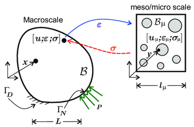
|
| Figure 1: Macrosctructure with an embedded local microstructure. |
(1) However, in one article supporting this work, dynamic problems are also considered. See [72]
2.1.1 RVE kinematics and strain tensor
In the context of the adopted first-order homogenization setting, the microscopic velocity field can be splitted as follows:
|
|
(2.1) |
where stands for the velocity at the macroscale, stands for the rate of infinitesimal macroscopic strain tensor, the term is a velocity term that varies linearly with , and the velocity fluctuations. The decomposition of the rate of microscopic strain tensor in the finite element framework yields, from the spatial differentiation of Eq. 2.1:
|
|
(2.2) |
The starting point of multi-scale constitutive settings, is the assumption that the rate of macroscopic strain , at a point of the macro-continuum, is the volume average of the rate of microscopic strain 2.2, over the RVE associated with . This assumption is also interpreted as the fact that the microscale deformations only influence the macroscale behavior through its volume average.
|
|
(2.3) |
In virtue of 2.2 and 2.3, this condition is equivalent to impose the volume average of the symmetric gradient of the velocity fluctuations to vanish. This condition can be written using the Gauss theorem as a constraint over , involving the whole volume of the RVE, as follows:
|
|
(2.4) |
where is defined as the space of admissible microscale velocity fluctuations in the RVE, stands for the boundary of the domain , and is the unit normal vector on . Equation 2.4 is also known as the minimum constraint boundary condition.
The actual set of kinematically admissible velocity fields , together with the associated space of virtual kinematically admissible velocities at the microscale, denoted by , play a fundamental role in the variational formulation of the equilibrium problem of the microscale. This space can be defined as follows:
|
|
(2.6) |
In virtue of 2.4, and the fact that is itself a vector space, it can be concluded from 2.4 that:
|
|
(2.7) |
Furthermore, the same arguments can be applied to the total form, and establish that any kinematically admissible displacement fluctuation belongs also to .
2.1.2 Hill-Mandel Principle of Macro-Homogeneity
The scale bridging equations are completed by introducing the Hill-Mandel Principle of Macro-Homogeneity [20,21]. Based on physical arguments, this Principle states that the macroscopic stress power equates the volume average over the RVE of the microscopic stress power, making both, macroscale and microscale, continuum descriptors energetically equivalent. Thus, departing from:
|
|
(2.8) |
where , stands for the space of all second order macroscopic strain tensor functions, Eq. 2.8 is similar to Eq. 2.2, but for admissible strain variations. Therefore, the following identity holds:
|
|
(2.9) |
In particular, taking , and , yields:
|
|
(2.10) |
where, stands for the macroscopic stress tensor, which turns out to be as the volume average of the microscopic stress . Equation 2.10 is also fulfilled in rate form. In addition to Eq. 2.10, the following condition emerges from the variational equation 2.9 solving for :
|
|
(2.11) |
Eq. 2.11 defines the variational microscale equilibrium problem (or microscale virtual power principle).
2.2 Multiscale Fracture Mechanics issues
In Computational Fracture Mechanics, hierarchical multiscale methods involve additional issues. In particular:
- The existence of the RVE has been questioned in the literature, arguing that for fracture cases, the material loses its statistical homogeneity [52,26].
- The fact that the homogenized constitutive model lacks an internal length [77], raising similar issues than in classical phenomenological monoscale problems.
Additionally, mesh-bias dependence, and the proper fracture energy dissipation issues [78] via regularized constitutive models [79,48,50,80] are also crucial issues to be considered at each scale.
Along this section, the most important aspects of the proposed multiscale approach are summarized. This multiscale approach is fully detailed in Paper in Sec. 5.2.
2.2.1 Multiscale modeling setting
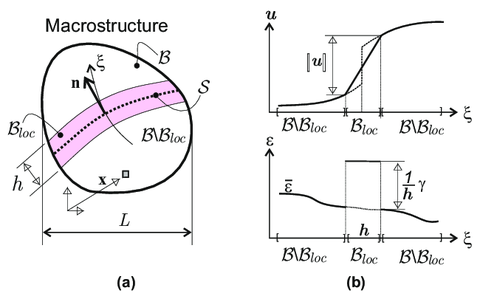
|
| Figure 2: Macroscopic (Structural scale) body (a) subdivision in a non-smooth domain , and a smooth domain (b) h-regularized displacement and strain discontinuity kinematics. |
2.2.1.1 Macroscale Model
Considering the body , at the macroscale (see Fig. 2) it is assumed that material points, , of the macroscopic body belong, at the current time , to either one of the two subdomains:
- Domain : the set of points at the macroscale, exhibiting smooth behavior. The infinitesimal strain field is described in rate form, as:
|
|
(2.19) |
where is the macroscopic displacement field, stands for the time or pseudo-time parameter, and , stands for the symmetric counterpart of .
- Domain : the set of points exhibiting material failure and, therefore, a non-smooth behavior. 1 The strain field at these points is assumed to be captured by a h-regularized strong-weak discontinuity kinematics, h being the width of the corresponding strain localization band (see Fig. 2-(b)).
|
|
(2.20) |
In Eq. 2.20, stands for the regular (smooth) counterpart of the strain, is a colocation (characteristic) function on (See. Fig. 3), so that the term becomes a h-regularized Dirac's delta function shifted to the center-line, (the macroscopic discontinuity-path at the current time , as shown in Fig. 2-(a)). Thus, in Eq. 2.20, the term corresponds to the non-smooth (discontinuous and h-regularized) localized counterpart of the strains; a space-discontinuous second order tensor for the weak-discontinuity case.
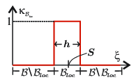
|
| Figure 3: Colocation function |
2.2.1.2 Microscale Model
Assuming that the fracture at the macroscale has arisen, in turn, by the appearance of failure mechanisms at the microscale level, originated by some type of material failure. The next step is to endow the microscale model with mechanisms to capture the onset and propagation of this material failure. Therefore, without introducing further details, it is considered that the microstructure shall be able to capture some dominant failure mechanisms of the material.
|
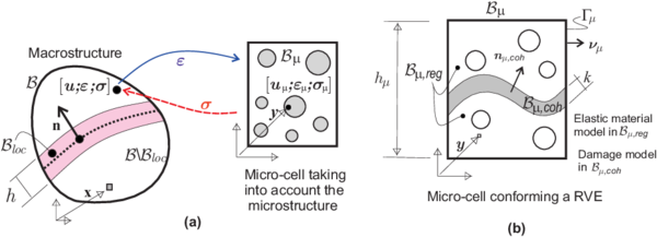
| Figure 4: Outline of the multiscale model for propagating fracture: a) macro and micro scales; b) microcell model accounting for material failure. |
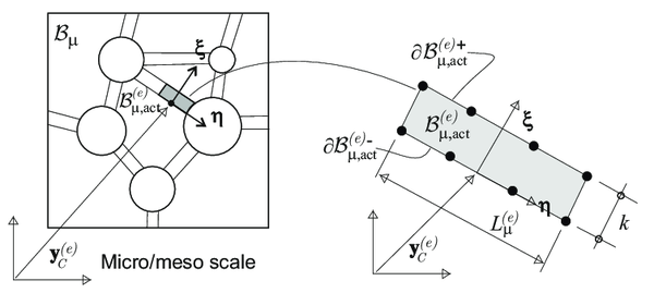
For this purpose, a micro failure cell , of characteristic size , is considered to exist at every material point . It accounts for the material morphology at the microscale (voids, inclusions etc.). In addition, it is endowed with a set of cohesive bands () of very small width , whose position and other geometric properties (typically the normal , see Fig. 4) are predefined. At the current time , the activation (de-cohesion) of a number of those bands, defines the current subset of active bands which constitutes the "active" microscopic failure mechanism, for the considered point .
In principle, there is no intrinsic limitation on the number of the "candidate" cohesive bands to be considered at the failure cell. On one hand, their number and spatial position have to be sufficient to capture the dominant material failure mechanisms at the macroscale. On the other hand, the associated computational cost sets a limitation on the number of such bands. In this context, the following domains at the microscale are considered (see Fig. 4):
- Domain : the set of points , which do not belong to the cohesive bands. They are compelled to exhibit a smooth behavior described by a Continuum hardening model, typically:
|
|
(2.21) |
where and stand, respectively, for the stress and strain fields at the microscale point, , of the failure cell (corresponding to the macroscale point ), being the microscopic inelastic constitutive tensor derived from the hardening constitutive model.
- Domain : the set of microscale cohesive bands. As for the material behavior, the disctintion of two situations has to be made in this case:
- The failure cell, is associated to a non-smooth material point at the macroscale (). Without limiting the use of any other inelastic constitutive model, this domain is endowed with an isotropic continuum damage model, exhibiting inelasticity with regularized strain softening only for tensile stress - tensile-damage continuum damage model [84,85,86]. Its constitutive response is2 represented in a general form as:
|
|
(2.22) |
where stands for a set of internal variables accounting for the inelastic behavior evolution.
- The failure cell, is associated to a smooth material point at the macroscale, (). In this case, the inelastic model, in Eq. 2.22 is enforced to behave instantaneously elastic at the cohesive bands domain, , :
|
|
(2.23) |
where, in continuum damage models, with , and being the rate of the damage internal variable (a scalar for isotropic damage cases).
An advantage of this methodology, in the previous setting, is that the same failure cell morphology is considered to represent the microstructure at every macroscopic point of , both for and . The only difference is the considered constitutive behavior at the cohesive bands , defined in Eqs. 2.21,2.22 and 2.23.
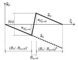
Displacement fluctuations in the CSDA: Considering Eq. 2.1, with a local coordinate system () aligned with the domain (see Fig. 4), and, exhibiting the de-cohesive behavior allocated to the cohesive bands, the smooth part of the microscopic displacement fluctuation field, , can be expressed as:
|
|
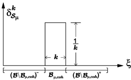
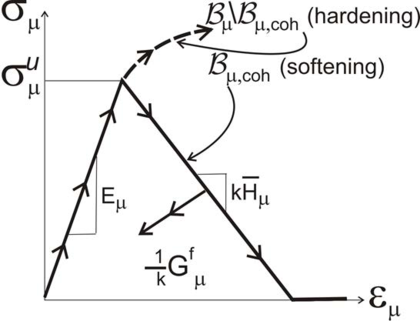
| Figure 5: Cohesive Band behavior. | |
|
|
(2.25) |
where is the k-regularized Heaviside function shifted to , and is a (smooth) function arbitrarily defined except for the restriction in Eq. 2.25-(c), In Eq. 2.25 , is the apparent jump of across the cohesive band.
Following these statements, the microscale displacement fluctuation is given by (see Fig. 5):
|
|
(2.26) |
Eq. 2.26 constitutes the displacement counterpart of a k-regularized strong discontinuity kinematics [87], and proves that the herein proposed cohesive-bands approach, is consistent with a k-regularized strong discontinuity at the cohesive domain . In consequence, the corresponding microscopic strain fluctuation field is given by:
|
|
(2.27) |
where stands for the k-regularized Dirac delta function, placed at the center line, , of (see Fig. 5-(b)). Thus, the rate of microscopic strain field can be written in terms of the rate of macroscopic strain , and the rate of microscopic displacement fluctuations , as follows:
|
|
(2.28) |
From Eq. 2.28, it can be concluded, that the second term at the right-hand side becomes unbounded in the limit . In multiscale modeling, this expression is equivalent to the one given, in phenomenological monoscale models, in the context of the Continuum Strong Discontinuity Approach (CSDA) of material failure [48].
(1) See: Sec.2.1 Paper 2
(2) See: Sec.2.2 Paper 2
2.2.2 Homogenized (induced) constitutive equation
One of the most specific features of the proposed multiscale approach, is that the same homogenization setting is used in points of both domains, smooth (), and non-smooth (), coinciding with the approach presented in Sec. 2.1. Other approaches [30], redefine the failure cell along time, fulfilling conditions of material bifurcation induced by instabilities at the microscale. More complex approaches [66,88,89,90] propose the use of second-order computational homogenization schemes in order to get better accuracy in the prediction of high strain gradients. In this work it is claimed the ability of the proposed approach to induce discrete failure in a first-order homogenization setting, giving rise to objective responses, and proper energy transfer through scales.
An issue appearing in this scenario, widely known in hierarchical multiscale approaches, is its high computational cost. In this context, the proposed model was also conceived to be combined with the use of model order reduction techniques (Paper ) [91]. These techniques have been deeply studied in this work, and their main features are presented in Chapter 3.
In what follows, the consequences of the homogenization procedure based on the Hill-Mandel Principle of Macro-homogeneity are analyzed. The fact that the regularized strong discontinuities appear also at the microscale, being captured by the cohesive bands , is one of the most relevant features of the proposed approach.
|
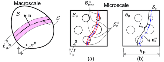
| Figure 6: Multiscale model: (a) failure cell with activated failure mode; (b) geometrical characterization of the failure mode. |
For the sake of generality, the RVE is considered composed by several components: a matrix, and randomly distributed inclusions and voids. In addition, a number of cohesive bands are considered defining the set (a sketch is presented in Fig. 6); those cohesive bands allow failure within the matrix, 1 across the aggregates and at the matrix/aggregate interface.
Following the previous domain decomposition (smooth and non-smooth subdomains) in Sec. 2.2.1.2, the Eq. 2.10 can be integrated in the two separated subdomains:
|
|
(2.30) |
In consonance with the definition of (in particular, the bounded behavior of the microscopic stress field), the second term on the right hand side can be neglected assuming a small enough width of the cohesive bands ().
Finally, after some manipulations of Eq. 2.30, and following the definitions of microscale kinematics in Eq. 2.28, and the lemma in Eq. 23 in Paper [80], the resulting homogenized constitutive equation fulfills the following:
|
|
(2.35) |
|
|
(2.36) |
|
|
(2.37) |
where, stands for a characteristic length, depending on the activated microscopic failure pattern. The tensorial entities and , are inelastic strains, and play the same role than internal variables in phenomenological models. However, unlike them, here, 2 their evolution is determined, at every macroscopic sampling point , by homogenized values of entities at the corresponding microscopic failure cell . This extends to non-smooth problems, some theoretical results already derived for smooth problems, see [92,93]. In addition, a characteristic length emerges naturally in Eq. 2.36, as the ratio between the measure of the failure cell (area in 2D and volume in 3D), and the measure (length/surface) of the activated microscopic failure mechanism. In consequence this length is of the order of the failure cell size. For a deeper review of the analytical results of this induced homogenized constitutive model, the reader is addressed to Sec. 2.4 in Paper .
The role of the characteristic length, , naturally derived from the present formulation, is not only computational, but it has also other very relevant physical and mechanical implications. Consideration of such a characteristic length, for multiscale based approaches, has been claimed from the material mechanics community [77], and sometimes introduced in a heuristic way in other approaches [94]. This characteristic length depends on both the specific data of the problem and the local microscopic failure state. Through its consideration, the correct energy transfer between scales and mesh size objectivity can be achieved.
In summary, Eq. 2.35 and Eq. 2.36 retrieve the format of a constitutive model equipped with an internal length and with internal variables whose evolution is described by the microstructure behavior. Although this model will never be used for computational purposes3, it supplies relevant insights on the properties of the resulting homogenized constitutive model.
(1) See: Sec.2.4 Paper 2
(2) See: Sec.2.4 Paper 2
(3) Instead, the homogenized value of the stress in Eq. 2.10 is point-wise used to evaluate the current macroscopic stress in terms of the corresponding macroscopic strain.
2.2.3 Energy dissipation
Let us consider, on one hand the fracture energy, corresponding to points , defined as a material property specific for every compound of the heterogeneous RVE, and, on the other hand, the macroscale fracture energy , obtained as an output from the homogenization procedure. According to their definitions, those fracture energies can be computed in terms of fracture energy densities, in terms of the energy dissipation that takes place in bands with bandwidth (at the microscale) and (at the macroscale), respectively.
|
In virtue of the Hill-Mandel Principle of Macro-Homogeneity, 1 it can be concluded that the macroscopic fracture energy is equivalent to the average of microscopic fracture energy , along the activated failure mechanism at the microscale . Replacing Eq. 2.41 into Eq. 2.9, and after some manipulations, the macroscopic fracture energy is given by the expression [80]:
|
|
(2.43) |
|
|
(2.44) |
where is the mean value of the microscopic fracture energy varying along the active failure path. Eq. 2.44 provides the relationship of fracture energies at both scales. In case of an homogeneous fracture energy at the active cohesive bands of the microscale, Eq. 2.40 translates into an exact equivalence of fracture energies along the scales, :
|
|
(2.45) |
In the light of this result, it can be easily concluded that the fracture energies at the microscale determine, in average, the effective fracture energy at the macroscale. It is stressed the importance of the characteristic length in order to guarantee the proper dissipation between scales. For more details, the reader is addressed to Appendix B in Paper .
(1) See: Sec.2.6 Paper 2
2.2.4 Numerical aspects: finite element model
The proposed multiscale formulation has been implemented in a Finite Element model following the setting of a FE strategy. Accordingly, two nested finite element models are used:
- At the macroscale level, an EFEM based on the CSDA is used, aiming at capturing propagating cracks. As described in [1], this technology consists of the insertion, during specific stages of the simulation, of goal oriented specific strain fields via mixed finite element formulations. This allows modeling propagating cracks through the macroscale finite element mesh.
- A standard Finite Element model is used at the microscale level, combining standard elements endowed with continuum hardening constitutive models and cohesive-band elements endowed with regularized constitutive softening models. These are placed in the edges of every finite element, capturing the crack onset and strain localization, similar to the cohesive interface elements in [33], and more recently in [36]. This approach benefits the simplicity of the algorithm and the non-intrusive character of its implementation.
In what follows, these two finite element models are described.
2.2.4.1 Failure cell finite element model
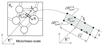
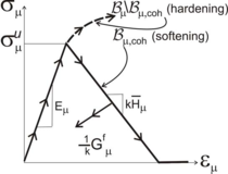
Standard quadrilateral finite elements are adopted for the numerical simulation of the cell response. The cohesive bands are also modeled by quadrilateral isoparametric finite elements of very small thickness (high aspect ratio), as shown in Fig. 7-(a), endowed with constitutive models whose behavior is sketched in Fig. 7-(b) and defined through equations 2.21 to 2.23. The remaining finite elements of the cell are endowed with either elastic or inelastic hardening responses. Therefore, only elements on the cohesive bands can exhibit strain localization.
The corresponding nonlinear problem in the failure cell is then solved for the discretized version of the microscale displacement fluctuations, using Eq. 2.11. Dirichlet boundary conditions precluding rigid body motions, and minimal boundary conditions in Eq. 2.4, are also imposed.
|
|
| Figure 7: Multiscale model: finite element discretization at the microscale. | |
Material failure propagates naturally through the RVE, strain localization takes place at the finite elements defining the cohesive bands. At every time step of the analysis, those finite elements who are in loading state, define the active set of cohesive bands conforming the active failure mechanism.
2.2.4.2 Finite element model at the macroscale: material failure propagation
One of the most critical issues in computational modeling of material failure is the appropriate capture of the crack onset and propagation. When does failure trigger at a given material point? and how does it propagate?, these two questions are the cornerstone of material failure propagation algorithms.
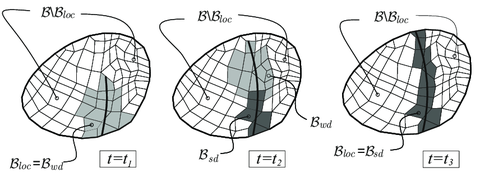
At the microscale, where the morphology and the position of candidate propagation mechanisms are predefined, the two issues are of minor relevance due to the adopted simplified failure-bands model. However, at the macroscale, there is not a predefined failure path, and in principle, any material point may fail and propagate in any direction. To adequately solve the previous questions, the procedure for modeling onset and propagation of discontinuities recently developed for monoscale problems [1] has been extended to the multiscale setting. The proposed methodology is based on the use of the following specific techniques:
|
| Figure 8: Evolution of the injection domains for three typical stages () of the discontinuity propagation. |
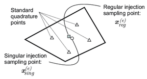
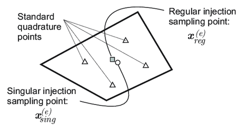
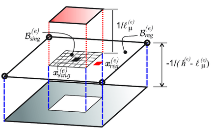
- Strain injection techniques: based on the use of goal oriented assumed-strain fields injected in selected domains, via mixed formulations [95,96,97,75]. The standard (four points) Gauss quadrature rule, corresponding to full integration of two-dimensional quadrilaterals, is complemented with two additional sampling points placed at the barycenter of the element (see Fig. 9), termed singular and regular sampling points. These two additional quadrature points sample the stresses similarly to the standard Gauss points. Therefore, for the injected elements, numerical integration (typically evaluation of the incremental internal forces in terms of the stresses), is based on those two additional sampling points by defining the weight indicated in Table 3 - in Appendix B in Paper . As for propagation purposes, two different enhanced strain injection stages, are considered1:
|
| Figure 9: Sampling points involved in the numerical integration. |
- In a first stage, the weak discontinuity stage, embedded localization bands with bandwidth , at the macroscale, are incrementally injected (prior to development of displacement discontinuities) in an evolving subdomain. These embedded localization bands have no preferred orientation (they have an isotropic character), and exhibit a great ability to propagate material failure in the proper directions. This so-injected elements are used for a very short time in order to avoid stress locking effects. Once the crack propagation remains stable, and the crack path is well defined, the injection stage is switched to the second stage.
The injected strain rate at element , with nodes, is the following:
|
|
(2.50) |
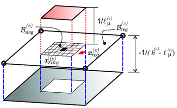
|
| Figure 10: Weak discontinuity mode. Elemental regularized dipole function . |
- In a second stage, the strong discontinuity stage, the obtained crack path field, , is used to determine the appropriate placement of an elemental embedded strong discontinuity strain field, which is incrementally injected in the appropriated set of elements .
In the present multiscale context, the proposed second stage consists of the incremental injection of the following elemental strong discontinuity mode:
|
|
(2.53) |
in terms of the -regularized Dirac delta function (displayed in Fig. 11), being the direction of the element normal provided by the solution of the discontinuous bifurcation problem presented in Sec. 2.5 in Paper . The resulting variational problem for the injection procedure is summarized in Box A2 - Appendix B in Paper .
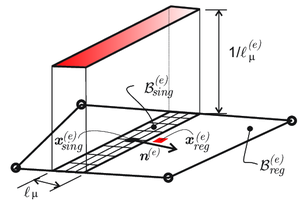
|
| Figure 11: Strong discontinuity mode. Elemental regularized Dirac delta function . |
- Crack-path-field techniques: their goal is the identification of the trace of the propagating crack by means of the so-called crack-path field. It is denoted as , and obtained from a selected localized scalar variable , which identifies the crack path as the locus where takes its transversal maximum value. In order to define this locus , some alternatives have been developed in this multiscale framework, see Eqs. in Paper [80]. The variational statement for the crack-path field model is fully detailed in Box 3.1 in Paper .
The resulting procedure is a robust and efficient technique to model propagating material failure in a finite element setting. It is especially appropriate for capturing material failure propagation in coarse meshes, in contraposition of the alternative extra elemental character techniques (phase-field, gradient or non-local damage models), where several elements span the localization band. In addition, its implementation in an existing finite element code has a little intrusive character.
In regards to the space and time integrations, as commented above, injection of weak-discontinuity and strong-discontinuity modes requires, in principle, specific integration rules in space, : a standard four-point Gauss quadrature rule, and two additional sampling points, for injected elements, and so that . Since those domains evolve along time (see Fig. 8), some additional problems on the time-integration of the resulting equilibrium equations are found. To tackle this issue, in [1] and [80] is proven that defining some "equivalent" stress entities at the standard Gauss points, the spatial integration can be rephrased as a standard four Gauss points integration rule in the integration domain. This space-time integration rule is fully explained in Appendix B3 in Paper , and the corresponding stress evaluation is also summarized in Box A3.
(1) To switch between stages, a set of control variables are defined, all those detailed in Sec. 3 and Appendix B in Paper
(2) Under the CSDA, the homogenized dissipation is evaluated at the barycenter of the finite element, denoted by
(3) For a deeper review of the bifurcation analysis, and, the definition of the corresponding bifurcation time , the reader is referred to Sec. 2.5 in Paper , and, for numerical aspects [98].
3 Model Order Reduction in Multiscale Analysis
3.1 General Framework
Along this work, some techniques for reducing the unaffordable computational cost inherent to the numerical simulation of multiscale fracture problems have been developed. Those techniques are combined to obtain a hyper-reduced order model HPROM, based on a two-stage strategy:
- First Stage: also termed ROM, consists of a Galerkin projection, via Proper Orthogonal Decomposition (POD), onto a small space (reduced-order manifold), in which the set of modes conforming the projection basis are computed off-line.
- Second Stage: also called HyPer-Reduced Order Model (HPROM). Two different techniques have been developed here. The first one is based on interpolation methods, widely applied in problems exhibiting hardening behavior (see Paper ) [99]. The second one, based on a Reduced Optimal Quadrature (ROQ) rule, has been applied to fracture (non-smooth) problems. Similarly to the previous stage, the reduced modes functions used to reconstruct the state variables, are computed off-line.
In what follows, these techniques have been applied to the microscale BVP, while the finite element model at the macroscale remains as the standard one.
3.2 Reduced-order modeling (ROM) of the RVE problem
The model order reduction concept relies on the premise that, for any input parameter governing the microscale displacement fluctuations , the solution can be approximated by a set of linearly independent basis functions approximately spanning the primal variable1 space.
Following this idea, the off-line stage is devoted to determine via a POD technique, the reduced basis in which the HF solution is projected. Once this basis has been obtained, a subsequent online stage in the reduced-space is considered.
(1) Primal variable is known as the selected variable to perform the reduction process.
3.2.1 Computation of the reduced basis functions
Taking as a primal variable the displacement fluctuations, and departing from the problem depicted in Sec. 2.1, a first step consists of determining an approximation1 of the finite element space of kinematically admissible microscale displacement fluctuations . This approximation is obtained as the span of the displacement fluctuation solutions obtained, for a judiciously chosen set of input strain trajectories, every trajectory being discretized into a number of steps . These set of finite element solutions are stored into the snapshot matrix as column vectors:
|
|
(3.1) |
In consequence, the approximating space for , henceforth called the snapshot space, is then defined as:
|
|
(3.2) |
where, is the total number of snapshots.
Once the snapshot matrix has been computed, the Elastic-Inelastic decomposition technique is used to determine the reduced basis functions. The reason for it relies on the fact that the SVD applied to the whole matrix , may produce basis with a large number of elements, which makes difficult to retrieve the response of the RVE in some specific cases. Particularly, the elastic response2, might request a much larger number of basis functions, this translating into a significant waste of computational cost.
To eliminate this shortcoming, in this work, it is proposed a time partition of the space of snapshots into elastic (), and inelastic () subspaces.
|
|
(3.3) |
3obtaining the reduced basis as the combination (spatial sum) of both sub-bases. An orthonormal basis for is determined by taking a low number of elastic snapshots (at a minimum, for 2D problems, for 3D problems), and computing the corresponding orthonormal basis.
Once this set of elastic basis is known, the orthogonal projection of each snapshot onto the orthogonal complement of is computed; with this new set of snapshots, the inelastic basis functions are obtained via SVD. Finally, the assembled basis results the following:
|
|
(3.4) |
and the reduced-order space , spanned by this base, is:
|
|
(3.5) |
Placing the elastic modes in the first positions, followed by the essential4 inelastic modes, ensures the reduced-order model to deliver linear elastic solutions with the same accuracy than the HF solutions. For more details, the reader is encouraged to sent to the Appendix B in [99].
3.2.1.1 Formulation of the reduced order model
Once the reduced basis is computed, 5 the online stage consists of solving the discrete version of the microscale equilibrium equation (via FE), projected onto the reduced-order space spanned by . To this end, the test and trial functions, and , are approximated by the following linear expansions:
|
|
(3.6) |
|
|
(3.7) |
where, and stand for the low-dimensional approximations of trial and test functions, respectively.
Introducing expressions 3.6 and 3.7 into the discrete version of the microscale BVP (see Sec. 4 in [99]), and multiplying the resulting expression by (Galerkin projection), it yields:
PROBLEM A (ROM) (Microscale reduced problem via POD):
Given the macroscale strain, , and the reduced basis for displacement fluctuations , find satisfying:
|
|
(3.8) |
where denotes the vector containing the coefficients associated to each basis function , being the basic unknowns for the standard reduced-order problem. stands for the reduced strain-displacement matrix “B-matrix” defined as . When using a Gauss quadrature integration scheme, is the total number of Gauss points of the mesh; denotes the weight associated to the g-th Gauss point ; and stand for the reduced B-matrix and the stress vector at Gauss point , respectively [100].
(1) In general, cannot be precisely determined, such a task will require finite element analyses of the cell under all conceivable strain paths. Rather, one has to be content to construct an approximation of it.
(2) Under an infinitesimal strain framework, this response is exactly recovered with only three basis [99].
(3) See: App. B Paper 1
(4) Essential based on a threshold given by an a-priori error estimation, see Sec. 9.4 in [99], thus, corresponds to the truncated version of the full base with dominant modes.
(5) See: Sec. 4 Paper 1
3.2.2 Specific issues in non-smooth (fracture) problems
3.2.2.1 Domain separation strategy
Taking advantage of the unbounded character of the microscale strain field typically observed in this kind of problems, the failure cell is splitted into a regular domain (made of elastic matrix and possible inclusions) and a cohesive domain (cohesive bands exhibiting a softening cohesive behavior). Details on this issue can be found in Sec. 3.2.2 in Paper [91].
3.2.3 Formulation of the microscale saddle-point problem
In addition to this proposal, the ROM of the failure cell is formulated in an unconventional manner, : in terms of strain fluctuations rather than in terms of conventional displacement fluctuations.
As it will be shown later, it is convenient to rephrase the original problem, posed in terms of displacement fluctuations (PROBLEM-I in Paper ). The primary unknowns of the rephrased problem are now the microscale strain fluctuations instead of its displacement fluctuations, while the constrained original minimum problem (of the standard micro-cell BVP) is rewritten in terms of a Lagrange functional. The resulting formulation is a variationally consistent saddle-point formulation.
Considering the material free energy for the isotropic damage model in , the microscale stress field can be expressed as:
|
|
(3.9) |
complemented by the evolution laws of the internal variables [101]. Thus, in consonance with the hierarchical multiscale approach, the following parametrized functional can be defined:
|
|
(3.10) |
where, , is a symmetric second order tensor Lagrange multiplier enforcing condition 2.4 on the microscale strain fluctuations . With this parametrized functional , a saddle-point problem can be stated as:
PROBLEM II (HF) (Microscale saddle-point problem): Given the macroscale strain, , find and satisfying:
|
|
(3.11) |
Such that:
|
|
where stands for the space of microscale kinematically compatible strain fluctuations and, stands for the evolution equation of the internal variables. After considering that the microscale stress field is given by Eq. 3.9, the following optimality conditions emerge:
|
Eqs. 3.12 and 3.13 provide the solution of the saddle-point problem stated in Eq. 3.11. It can be proven that Eqs. 3.12 and 3.13 make PROBLEM II equivalent to the original problem in Eq. 2.11, but now rephrased in terms of the microscale strain fluctuations (see PROBLEM I-R in Paper ).
3.2.3.1 Computation of the reduced basis functions
The transition from the high-dimensional finite element space to the reduced-order space, is accomplished by applying the POD technique, now for non-smooth problems. The standard reduced order model is based on the reduction of the strain fluctuation field . The first step consists of generating a collection of solutions (samples) from different trial loading cases, representatives of all possible loading cases.
In each trial case, the microscale strain fluctuation at every Gauss point, is collected and stored in the snapshot matrix as a column vector:
|
|
|
|
(3.14) |
where is the number of snapshots vectors. 1 Therefore, represents a number of sampled solutions obtained with the HF model under different loading conditions. For more details, the reader is addressed to Sec. 4 in [102].
In order to get a more accurate estimation of the dominant modes of the microscale strain fluctuations, it is convenient to separate the microscale into specific sub-blocks in accordance with the type of material response observed during the load history. The procedure is sketched in Fig. 12:
In addition, the Elastic-Inelastic snapshot decomposition above explained [99], 2 is also applied to each sub-block. Thus, without loss of generality, the snapshot entries are organized so that the first, entries correspond to Gauss points in , while the remaining entries correspond to Gauss points in .
In accordance with this criterion, the snapshot matrix 3.14 can now be partitioned into sub-matrices as follows:
|
|
(3.15) |
where and collect the strain fluctuations located outside and inside the cohesive bands, respectively. The right hand side matrix in 3.15 emphasizes the double partition performed in accordance with elastic-inelastic regimes.
After some additional manipulations, the corresponding set of orthonormal basis is obtained as:
|
|
(3.17) |
The number of reduced basis in is: , where the values and are obtained from the SVD applied to the projected inelastic snapshots. Additional details can be found in Sec. 3.2.2 in Paper .
3.2.3.2 Formulation of the reduced order model
Once the reduced basis is known, the strain fluctuations are interpolated as a linear combination of the elements of this basis as:
|
|
(3.18) |
where each element , of the basis , is a microscale strain fluctuation mode and the vector of time dependent coefficients () represents their corresponding amplitudes (the actual unknowns of the problem). 3 In the same way, the variations of the microscale strain fluctuations are expressed similar to 3.18 as:
|
|
(3.19) |
The problem solved in the online stage is then the following:
PROBLEM III (ROM) (RVE saddle point problem): Given the macroscale strain, , find and satisfying:
|
|
(3.20) |
|
|
such that:
|
|
The optimality conditions for the problem above yield:
|
which, expressed in matrix notation, yield:
|
where is the column vector constituted by piling-up the stress vectors, , evaluated at the integration Gauss points. The column vector is also the pilled-up of repeated values of the same constants vector . 4 The square diagonal matrix , and the rectangular matrix , collect the Gauss weights: , which for plane strain cases () are distributed in sub-block matrices , as follows:
|
|
(3.26) |
being a matrix with the corresponding -th Gauss weight placed at the diagonal.
The unknowns for the reduced order model are, the modal amplitudes , and the Lagrange multiplier .
Considering the system of equations 3.24 and 3.25 for and , it could be expected that this problem, of equations, should be less computationally costly, than the HF model. However, this is not the case: the numerical simulations with the ROM model do not substantially reduce the computational cost, and little (or even smaller than one) speedups are obtained. This fact highlights that the actual bottleneck for fast online computation is not the solution of the balance equations but, rather, the determination of the stresses, internal forces and stiffness matrices at every integration point of the underlying finite element mesh. Therefore, an additional technique is proposed to reduce the amount of integration points in which the constitutive equation is evaluated.
(1) See: Sec.4 Paper 3
(2) See: Sec.3.2.2 Paper 3
(3) See: Sec.3.1 Paper 3
(4) See: Sec. 3.2 Paper 3
3.3 Numerical Integration: Reduced Order Quadrature Technique (ROQ)
Attention is then focused on reducing the computational cost arisen by the use of a classical Gauss quadrature for the numerical integration of the optimality conditions (Eqs. 3.22 and 3.23).
For this purpose, a reduced integration technique has been developed by resorting to a nonconventional method, termed Reduced Optimal Quadrature (ROQ), to integrate the term involving the microscale free energy in 3.20:
|
|
(3.43) |
Where stands for he ROQ.
The ROQ technique is based on selecting, from the initial set of “Gauss” sampling points, and through an adequate algorithm, an equivalent subset of sampling points , and their new corresponding weights . The success of the reduced integration numerical scheme, in front of the conventional Gauss quadrature, lies on the fact that it is possible to reduce notably the number of involved quadrature points to , being the number of integration points for the Gauss quadrature scheme, keeping under strict control, or even reducing to zero, the numerical error introduced by the reduced quadrature rule. Then, the microscale potential energy in Eq. 3.43, is re-expressed as:
|
|
(3.44) |
In consequence, the corresponding optimality conditions (equilibrium equations) to be solved during the online stage are:
PROBLEM IV (HPROM) (Microscale reduced saddle-point problem): Given the macroscale strain, , find and satisfying:
|
A similar procedure could also be used for the integral terms (underlined as “Gauss quadrature”) in Eqs. 3.45 and 3.46. However, this would not produce a substantial computational cost gain due to the fact that those terms are constant (not depending neither on the unknowns of the problem nor on the constitutive internal variables). They are required to be integrated only once, via the standard Gauss quadrature, and the result can be stored, and retrieved when necessary, during the online stage execution.
(1) See: Sec. 5.2 Paper 1
(2) See: Sec. 5.2 Paper 1
(3) For a deeper review of this approach, the reader is encouraged to read the Sec. 5.3 in [99]
(4) See: Sec. 5.3.2 Paper 1
(5) In this context, observed means calulated through the pertinent constitutive equation.
(6) The operator is the so-called selection operator associated to sampling indices , for instance, the restricted matrix of weighted strain modes is defined as
(7) The selection criterion used for the set of sampling points in this approach, is fully explained in Sec. 7 in [99], details about the optimality criteria, and its corresponding accuracy are deeply detailed in this section.
(8) See: Sec. 6.3 Paper 1
3.3.2 Reduced Optimal Quadrature
In spite that the goal of the ROQ is to develop a reduced cost interpolation scheme as a general framework for both static and dynamic problems, attention is focussed here on the multiscale quasi-static fracture problems. The minimum number of quadrature points providing an admissible integration error in the free energy integral, 3.43 is based on the optimal linear expansion of in terms of the free energy modes and its corresponding amplitudes . Thus, a similar expression to Eq. 3.18) can be adopted for constructing the reduced microscale strain fluctuations, as follows:
|
|
(3.47) |
With the previous approximation in hand, the total microscale free energy can be expressed as:
|
|
(3.48) |
3.3.3 A Greedy algorithm for obtaining a reduced quadrature rule
In order to obtain the reduced optimal numerical quadrature rule, the following optimization problem is considered:
OPTIMIZATION PROBLEM : Given the expanded reduced basis , and the set of sampling points , find and satisfying:
|
|
(3.49) |
being:
|
|
(3.50) |
Where, and stand for the error committed through the reduced integration of every free energy reduced basis function, and the error in the integration of the volume , respectively. The resulting algorithm (described in the flowchart of Box IV 1 in Sec. 5 of Paper [72]) returns a sub-set of optimal Gauss points, and the corresponding weights, that integrate exactly the basis and, therefore, the free energy in Eq. 3.47.
3.3.3.1 Computation of the reduced basis functions
Regarding the computation of the microscale energy reduced basis , a SVD-based strategy is used in the off-line stage, similar to that described in Sec. 3.2.1.
The method is again based on the construction of a snapshots matrix, in this case, for the free energy, and the computation of its corresponding reduced basis via SVD. For this purpose, two options appear:
- To construct the microscale energy snapshots by collecting solutions of the ROM in 3.20. This strategy implies the following actions: (a) the ROM is constructed considering a number of microscale strain fluctuation modes . In consequence, the obtained energy snapshots matrix provides a reduced basis, which spans a space determined by the selected set of strain fluctuation modes.
- To construct the microscale energy snapshots by collecting solutions of the HF model in 3.11. This strategy computes simultaneously the microscale energy and the strain fluctuation snapshots. The resulting reduced bases are consequently independent from each other, but converging to the HF solution as the number of strain basis functions , and energy basis functions , increase.
The first method is considered as the algorithmically consistent strategy. However, it is also more expensive than the second one. The reason relies on the fact that, in order to get the reduced basis for the microscale energy , training trajectories have to be computed twice: a) First using the HF model to obtain the strain modes , b) Second, using the ROM model to obtain the corresponding free-energy modes .
Both strategies have been tested and both provide accurate results. However, the later, being the cheaper and simpler one, was adopted as the most convenient.
In summary, both the strains and the free energies of the microscale are sampled simultaneously at the off-line stage, for different sampling trajectories with the HF model, and a series of snapshots of energy, , are evaluated and collected for each Gauss point. Then, the microscale energy snapshot matrix is built as:
|
|
|
|
(3.61) |
In accordance with the position of the Gauss point,9 in the finite element mesh, and following a similar procedure to that adopted in Eq. 3.15, this snapshot matrix is also partitioned into components associated to the domains and as:
|
|
(3.62) |
and the SVD technique is then separately applied to both partitions of to obtain two distinct (orthogonal) bases, for the elastic regime of both subdomains:
|
|
(3.63) |
The corresponding inelastic reduced basis functions are also computed via SVD, following a procedure similar to the one described in Sec. 3.2.1. The complete reduced basis for the energy field , is made of the union of and :
|
|
(3.64) |
The number of basis vectors in is: , where the values of and are obtained from the solution of the SVD applied to the inelastic projected snapshots.
3.4 Numerical assessment and approximation errors
The accuracy of the reduced models, ROM and HPROM, depends on several aspects. In order to assess it, three different sets of tests are done:
- Consistency tests: A set of trajectories already sampled with the HF model during the microscale sampling process in the off-line stage, are re-evaluated using the ROM and HPROM strategies. This kind of assessment provides an estimation of the quality and richness of the basis to reproduce the stored snapshots, and the accuracy of the ROQ scheme. It is expected that the error with respect to the HF solutions (consistency error) tends to zero as the number of considered modes, for each reduction strategies, are increased.
- Accuracy tests: Similarly to the aforementioned consistency tests, the representative cell is subjected to a unsampled loading trajectory. In these cases, the quality of the reduced bases and the ROQ scheme is also tested. In contrast with the previous case, unsampled trajectories during the off-line stage, are not supposed to be exactly captured, due to the underlying sampling error.
- Multiscale structural tests: These kind of tests are based on multiscale benchmarks. The aim is to evaluate the accuracy of the solutions when the proposed overall HPROM strategy is applied, and to obtain the corresponding speed-ups.
Details on this issue can be found in Sec. 5 in Paper .
3.5 Representative example
A squared microscale model, made of a matrix and randomly distributed aggregates, is devised and tested (see figure 14) to simulate the microstructure of a cementitious-like material (concrete). Relevant details about the finite element model are presented in Table 1. To mimic the concrete material response, the failure cell is modeled with three components: aggregates, which are assumed to be elastic, bulk matrix, also assumed elastic, and interfaces (matrix-matrix and matrix-aggregates), which are modeled with cohesive-band equipped with an isotropic damage constitutive law. The properties of the components in the microscale are defined in Table 2.
|
| Figure 13: Failure cell |
| Number | Number | Number of | Total number of |
| of elements | of D.o.f. | Cohesive Bands | Gauss points () |
| 5409 | 14256 | 2189 | 21636 |
| [MPa] | [MPa] | [N/m] | ||
| Elastic matrix | 0.18 | –- | –- | |
| Elastic aggregate | 0.18 | –- | –- | |
| Cohesive bands of | 0.18 | 2.60 | 140 | |
| matrix-matrix interface | ||||
| Cohesive bands of | 0.18 | –- | –- | |
| matrix-aggregate interface |
3.5.1 Design of the HPROM Strategy
Figure 14 shows the summary of a number of results obtained by running the HPROM strategy in a number of cases for the microstructure in Fig. 13.
In general terms, Figure 14 can be used as an “abacus” for a-priori selection by the user of the HPROM strategy in a multiscale problem (for a given microstructure at the RVE). For instance, by selecting the admissible error ( 3,5%) in the top figure, the number of strain modes is obtained. Entering in the lower plot, with this result (), one obtains the suitable number of integration points and the expected speedup .
The availability of a catalog (constructed off-line) for a specific RVE microstructure, allows the user's a-priori selection of the appropriated HPROM strategy, by balancing the admissible error vs. the desired speedup.
3.5.2 Multiscale crack propagation problem: L-shaped panel
The test shown in Figure 15 is a benchmark commonly used for testing macroscale propagating fracture models. This concrete-like specimen is considered here to test the qualitative results and convergence properties of the proposed HPROM approach, when utilized in real FE multiscale crack propagation problems.
|
| Figure 15: L-shaped panel: a) Specimen geometry; b) Finite element mesh |
The geometry of the simulated specimen is depicted in Figure 15-a. As shown in Figure 15-b, the domain of the L-shaped panel is split into two domains: 1) the multiscale domain (with elements) corresponding to the region where the crack is expected to propagate, modeled with the HPROM of the microstructure depicted in Figure 13, and 2) the remaining part of the panel, which is modeled with an elastic monoscale approach (using 1709 elements), where the elasticity tensor is obtained through an elastic homogenization of the micro-structure elastic properties. Even for this (rather coarse) multiscale problem, the high fidelity HF computational solution is extremely costly to handle, until the point that, with the available computational resources1, it was not possible to display the complete action-response curve (in Fig. 16).
However, the remaining structural responses in Figure 16, obtained through a number of HPROM strategies, involve very reasonable computational costs, and they were obtained in advance with no previous knowledge of the HF results. The accuracy is very good, and a response indistinguishable from the HF can be obtained times faster (). A less accurate response, but with a fairly good agreement with the HF can be obtained with .
|
| Figure 16: L-shaped panel: Structural responses in terms of force P vs. vertical displacement , for different RVE HPROM strategies, and obtained speed-ups. |
In Fig. 17, the evolution of the microscale crack opening is shown. It is worth noting that, both, the microscale failure mechanism and displacement jump vary along the macroscale in agreement with the crack propagation direction observed at the macroscale.
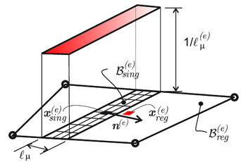
|
| Figure 17: L-shaped panel: microscale crack activation along the crack-path field, using and . |
This illustrates the new paradigm that is set and the computational possibilities open by the HPROM strategies in computational multiscale modeling explored in this work.
4 Discussion, Conclusions and Future Work
4.1 Discussion and Conclusions
4.1.1 Overview of the work
Multiscale modeling is foreseen to become a key approach to enable the next wave of design paradigms for engineering materials and structures. Indeed, it has an excellent potential to account for the physical links between different scales, involving the diverse phenomenologies intervening in the mechanical response of materials (grains, particles, defects, inclusions, etc.).
Quoting from a report by a group of experts to the US National Science Foundation [106]:
". . . . In recent years, a large and growing body of literature in physics, chemistry, biology, and engineering has focused on various methods to fit together simulation models of two or more scales, and this has led to the development of various multi-level modeling approaches. . . .. To date, however, progress on multiscale modeling has been agonizingly slow. Only a series of major breakthroughs will help us establish a general mathematical and computational framework for handling multiscale events and reveal to us the commonalities and limitations of existing methods . . . .".
In this sense, the effort invested in developing and using multiscale models, has been, in many cases, fruitless, due to the involved computational cost in this kind of methodologies. This limitation becomes a bottleneck for multiscale modeling, usually discarded, or, relegated to the availability of supercomputers, and, therefore, not always accessible to the whole computational mechanics community.
In addition, while multiscale models exhibiting material hardening behavior have widely been studied, multiscale models dealing with material softening behavior are in an early stages of development.
Therefore, the development of a reliable, minimally intrusive multiscale fracture models becomes a crucial task, not only in order to have a robust and consistent multiscale fracture numerical tools, but also for developing their related reduced order models that allow their use in complex cases that can be used for industrial purposes, with an affordable cost. These are the fundamental reasons for the research and development about this issues.
A sketch of the overall work carried out in this work is shown in Figure 18. In there, contributions are chronologically numbered and highlighted with a blue arrow. Contributed papers are numbered from P1, corresponding to the the first contribution (Paper ), to P6 (Paper ) the last one; in this context, CB means Chapter in Book.
In what follows, they are specifically commented, and the corresponding conclusions and achievements, are presented.
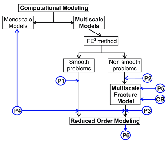
|
| Figure 18: Global Flow Chart of the work |
4.1.2 Paper \#1: J. A. Hernández, J. Oliver, A. E. Huespe, M. A. Caicedo, J. C. Cante. High-performance model reduction techniques in computational multiscale homogenization, Computer Methods in Applied Mechanics and Engineering - 2014, Volume 276, Pages 149–189
This Article presents the first research developments in this work on MOR techniques applied to multiscale modeling. The scope of this publication is limited to smooth problems and exclude fracture processes. Techniques like interpolation methods via HPROM have been studied.
The concept of a two-stage reduction (ROM-HPROM) is presented. The first reduction, denoted as ROM, is performed via POD, taking the displacement fluctuation field as a primal variable. The second reduction, denoted as HPROM, is performed via interpolation techniques (DEIM) of the microscale stress field.
It is shown that the interpolation-based HPROM obtained in this way, leads to an ill-posed mathematical formulation when the reduction process involves an interpolant constructed using POD modes provided by the primal variable (microscale stress field). This issue has been studied in the paper, and a robust and consistent solution has been proposed.
An additional aspect in this contribution, is the selection of the interpolation points for the stress field. These interpolation points are chosen guided, not only by accuracy requirements, but also by stability considerations.
The method of selection of the interpolation points (Greedy Algorithm) is, at the present, an intensive research field. However, although in the literature there are several alternative algorithms, none of them offers a robust and general treatment to handle this purposes.
Different measures of error have been presented to test the accuracy and the convergence. The work is assessed by the homogenization of a highly complex porous metal material. The results show that, the speed-up factor is about three orders of magnitude, for an error in stress smaller than .
As conclusions of this work, it can be stated that:
- The hyper-reduced form of the RVE equilibrium equation has a conceptual simplicity, and the corresponding solution scheme is also very simple to implement. Taking as departure point an existing FE code, one only has to replace the typical loop over elements in the FE code by a loop over the pre-selected sampling points.
- Storage of history data (internal variables) is only required at the pre-selected sampling points.
- Consistency with respect to the HF solution is achieved when the amount of reduced order basis functions, for both reductions, is increased.
In consequence, the numerical results suggest that this HPROM provides accurate solutions to problems exhibiting hardening behavior. However, some questions need to be further analyzed. For example:
- Can the model order reduction techniques capture the RVE solution in problems displaying crack propagation processes?
- Will the number of modes necessary to accurately replicate its solution, increase with the number of potential crack paths (i.e., with the geometrical complexity of the RVE)?
These questions motivated the next research work: the development of a reduced order model applied to problems exhibiting discontinuous fields, and in particular, the case of the quasi-brittle fracture.
4.1.3 Paper \#2: J. Oliver, M. Caicedo, E. Roubin, A. E. Huespe, J. A. Hernández. Continuum approach to computational multiscale modeling of propagating fracture, Computer Methods in Applied Mechanics and Engineering - 2015, Volume 294, Pages 384–427
This work presents a novel approach to two-scale modeling of propagating fracture, based on computational homogenization FE. The specific features of this contribution are:
- Extends the homogenization paradigms for smooth problems presented in Paper – typically the Hill–Mandel principle and the stress-strain homogenization procedures – to non-smooth problems.
- In both scales of analysis, a continuum (stress–strain) constitutive relationship is considered, instead of making use of the most common discrete traction/separation-law. This contributes to provide a unified setting for smooth and non-smooth, problems. This is achieved by resorting to the well-established Continuum Strong Discontinuity Approach (CSDA).
- As for the multiscale modeling issue, it involves a new and crucial additional entity: a characteristic length, which is point-wise obtained from the geometrical features of the failure mechanism developed at the low scale. As a specific feature of the presented approach, this characteristic length is exported, in addition to the homogenized stresses and the tangent constitutive operator, to the macroscale, and considered as the bandwidth of a propagating strain localization band, at that scale.
- Consistently with the characteristic length, a specific computational procedure is used for modeling the onset and propagation of this localization band at the macro-scale. It is based on the crack-path-field and strain injection techniques, developed [1]. This computational procedure ensures the macroscale mesh-size and microscale RVE-size objectivity of the results, and a consistent energy dissipation at both scales.
The approach has been validated and tested using classical benchmarks in fracture mechanics. After validation, some aspects of the proposed approach can be emphasized:
- From the computational point of view, the proposed technique is minimally invasive with regards to procedures well established in the literature on multiscale modeling of materials. In fact, in terms of the computational homogenization, the proposed approach displays no substantial difference with respect to the ones used for smooth (continuous) problems. In terms of material failure propagation, existing algorithms for monoscale crack propagation modeling can be easily extended to this multiscale case. In addition, this multiscale approach is extensible to other families of propagation schemes.
- Consistency has been assessed by comparison, with a number of representative cases, through results obtained with the proposed FE and the ones obtained by DNS. In the same way, objectivity have been also checked in terms of finite element mesh size and bias, at the macro-scale, and the failure-cell (size and shape) at the micro/meso scale.
As mentioned, multiscale computational fracture problems and their extension to 3D cases, face a great challenge: the enormous involved computational cost. In consequence, next step is the development of a reduced order model aiming at diminishing the computational burden of the developed multiscale fracture model.
4.1.3.1 HPROM for hardening processes applied to quasi-brittle fracture
The reduced order model described in Paper was used as a first attempt. However, the results were very unsatisfactory. The conclusions of this interpolation-based approach to multiscale reduced order modeling in fracture cases were:
- The reduced basis for the microscale displacement fluctuations obtained via SVD does not make a clear distinction between smooth and non-smooth domains. Hence, a large set of displacement modes (considerably larger than the one requested in hardening problems) has to be used to retrieve accurate solutions.
- The stress snapshots, taken from high localized strain stages with released near-to-zero stresses, are numerically neglected by the SVD1, this taking interpolation-based HPROM methods to fail in reproducing the post-critical stages.
- To obtain a good approximation with the HPROM, it is necessary to largely increase the number of displacement and stress modes, but, in this scenario, the interpolation method is not longer robust.
This suggests additional research and exploration of specific model order reduction techniques for multiscale fracture problems.
(1) The SVD strategy, gives importance to repeated snapshots, and mainly, snapshots which euclidean norm is considerably high.
4.1.4 Paper \#3: J. Oliver, M. Caicedo, A. E. Huespe, J. A. Hernández, E. Roubin. Reduced Order Modeling strategies for Computational Multiscale Fracture, Computer Methods in Applied Mechanics and Engineering - 2016, Volume 313, Pages 560–595
This article proposes a set of new computational techniques to solve multiscale problems via HPROM techniques. These techniques have been applied to the multiscale model described in 4.1.3, and they are summarized next:
- A domain separation strategy. The RVE is split into the regular domain (made of the elastic matrix and possible inclusions) and the singular domain (the cohesive bands exhibiting a softening cohesive behavior). These are designed to provide a sufficiently good representation of the microscopic fracture and of its effects on the homogenized material behavior [80]. The distinct constitutive behavior of both domains suggests a specific ROM strategy for each of them, in order to obtain a reduction strategy with information on the mechanical variables in every specific sub-domain. Therefore, selection of the ROM low-dimensional projection space is made independently for each of these domains.
- In combination with the previous strategy, the ROM for the RVE is formulated in an unconventional manner : in terms of the strain fluctuations rather than in terms of the conventional displacement fluctuations. The reduced strain fluctuation space is spanned by basis functions satisfying, by construction, the strain compatibility conditions, this guaranteeing that, after reduction, the solution in the strain fluctuation space also satisfies the strain compatibility.
- A specific Reduced Optimal Quadrature (ROQ) is used as a key technique to obtain relevant computational cost reduction from the ROM. This technique consists of replacing the standard Gauss integration rule by an optimal quadrature, involving much less sampling points, has been proposed in other works [107,72] as an ingredient of HyPer-Reduced Order Modeling (HPROM) strategies. In these works, the reduced numerical integration technique is applied to the variational equations of the problem (i.e. internal forces, involving n-dimensional vector entities) whereas, in the herein proposed approach, a similar reduced integration technique is applied, again unconventionally, to the primitive problem, i.e: the functional (a scalar entity) in the micro-scale saddle-point problem that supplies the RVE variational equations. In the present proposal, this functional turns out to be the stored energy (free energy) at the RVE, which, being a scalar entity, is much less demanding in terms of the integration rule.
In a first validation stage, in order to test the sensibility of the reduction techniques, a set of three different failure cells have been tested, by increasing the complexity and, consequently, the amount of cohesive bands. A-priori and a-posteriori errors analysis are performed, showing that, increasing the complexity (number of involved operations) at the microscale, the amount of required strain and free energy modes increases only slightly for a given error. This is a clearly promising scenario.
Finally, this reduced multiscale model was also validated and tested with the L-Shape Panel test, comparing the solution with the one given by the HF (obtained with the approach described in the Paper ), and analyzing the impact on the use of different amounts of reduced order basis functions of both, the strain fluctuations and the free energy.
Several aspects of the proposed methodology can be highlighted as new contributions:
- The RVE domain separation technique: to account for distinct constitutive models used at the RVE and take the maximum advantage of this distinction.
- A strain-based formulation of the variational RVE problem allowing a simpler application of the previous technique, without the need of introducing compatibility constraints.
- A specific sampling program, for the construction of the sets of snapshots in the off-line stage of the HPROM procedure, in accordance with the rest of elements of the proposed strategy.
- The Reduced Optimal Quadrature (ROQ) technique, which resorts to the primitive formulation of the RVE problem as a saddle-point problem.
At this point it can be argued that only idealized, two-dimensional, problems have been considered. The real interest of many multiscale modeling problems residing on actual three-dimensional problems, the following question arises:
to what extent these techniques can be extended to three-dimensional problems, where the involved RVE complexity and the associated computational cost can be two or three orders of magnitudes larger than in 2D problems?
In Fig. 19, the results obtained from different kind of 2D microscale morphologies are presented. They show a very relevant property: the obtained speedup “scales” linearly with the problem-complexity. Therefore one could think of achievable values of – for the speedup in 3D problems. This fact (in conjunction with, the additional usage of HPC procedures), could turn affordable 3D multiscale fracture modelling.
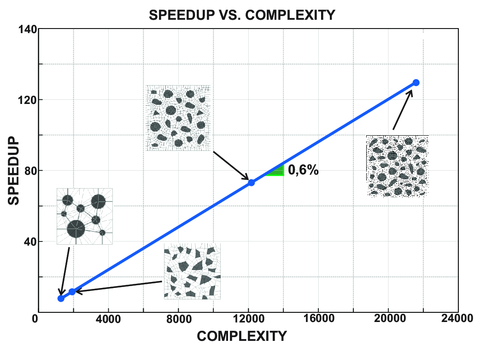
|
| Figure 19: Speedup scalability. |
4.1.5 Paper \#4: J. A. Hernández, M. A. Caicedo, A. Ferrer. Dimensional hyper-reduction of nonlinear finite element models via empirical cubature, Journal of Computer Methods in Applied Mechanics and Engineering - 2016, Volume 313, Pages 560–595
This work has been developed in combination with the reduced order model for non-smooth problems (see 4.1.4). The main objective is to develop the algorithmic procedure in a general setting to be applied to different problems involving integral operators that can be sampled. Not only problems involving multiple scales can be analyzed, but also monoscale (static and dynamic) problems based on the Finite Element method.
It is presented a general framework for the dimensional reduction in terms of numbers of degrees of freedom as well as number of integration points of nonlinear parametrized finite element models.
As in previous cases (see 4.1.2 and 4.1.4), the reduction process is divided into two sequential stages, the first consists of a Galerkin projection of the strain fluctuations, via POD, and the second consists of a novel cubature rule also used in 4.1.4. In this case, this method is deeply studied and analyzed. The distinguish features of the proposed method to be highlighted are:
- The minimization method is set in terms of orthogonal basis vectors (obtained via Singular Value Decomposition SVD) rater than in terms of snapshots taken from the integrand.
- The volume of the domain is exactly integrated.
- The selection algorithm does not require solve, in all iterations, a non-negative least-squares problem to obtain positive weights.
This model is tested through two structural examples, (quasi-static bending, and resonant vibration of elasto-plastic composite plates). The total amount of integration points is reduced three order of magnitudes, this methodology can be applied to different primary variables, in 4.1.4, attention was focused on use the free energy to determine the reduced integration rule.
Several issues have been improved by this research: firstly, the robustness, one of the most attractive features of the proposed hyper-reduced order model (and in general, of all cubature-based ROMs) is that it preserves the spectral properties of the Jacobian matrix of the finite element motion equations. Secondly, the improved version of the Empirical cubature method, in contrast with other similar techniques proposed in the literature, in which the weights at almost all iterations of the greedy algorithm are calculated with a standard, unconstrained least-squares. In fact, the nonnegative least squares problem is included to filter out small negative weights caused by roundoff errors. And finally, for implementation purposes, the "format" of the finite element method is conserved.
4.1.6 Paper \#5: J. Oliver, M. Caicedo, E. Roubin, A. E. Huespe. Continuum Approach to Computational Multi-Scale Modeling of Fracture, Key Engineering Materials - 2014, Volume 627, Pages 349–352
This work presents a brief summary of the two-scale approach for modeling failure propagation, providing details about propagation at the macro and micro levels. This publication is centered in exploring the applicability of the method to structural problems. The four-point bending and the Nooru-Mohamed problems have been chosen as benchmarks, taking the material properties form experimental tests.
In the case of the Nooru-Mohamed test, it has been shown, the influence of the horizontal load (shear force) in the microscale behavior, and the activation of different crack patterns, representing the macroscale changes in the crack propagation scheme. In the four-point bending test, it is displayed the influence on the macroscale propagation scheme, when critical failure mechanisms at the microscale are precluded.
4.1.7 Paper \#6: M. Caicedo, J. Oliver, A. E. Huespe, O. Lloberas-Valls. Model Order Reduction in computational multiscale fracture mechanics, Key Engineering Materials - 2016, Volume 713, Pages 248–253
This work has a similar objective than the previous one. A brief summary about the reduced order model based on the two-scale approach for modeling failure propagation, has been presented. This work also presents a summary about the results obtained in the L-Shaped Panel, and the influence of the size of reduced order basis functions (for strain fluctuations and free energy) is presented and analyzed.
4.1.8 Chapter In Book (CB): J. Oliver, M. Caicedo, E. Roubin, J. A. Hernández, A. E. Huespe. Multi-scale (FE²) analysis of material failure in cement-aggregate-type composite structures, Computational Modeling of Concrete Structures - 2014, Pages 39–49
This work focuses on exploring different issues of the two-scale approach for modeling failure propagation. Particularly, the total energy dissipation and its relation at both scales is analyzed in some specific fracture problems.
4.2 Ongoing work and future research lines
4.2.1 Ongoing work
- Most of the real industrial problems require 3D modelling. This is the reason because an immediate task is to extend all procedures developed in this work to 3D problems. This extension is carried out in Kratos Multi-Physics, an open-source code developed at CIMNE (International Center for Numerical Methods in Engineering).
- The approach developed in Paper is being extended to nonlinear geometrical multiscale problems. Considering an elasto-plastic constitutive model endowed, with hardening behavior, the goal is to study and analyze geometric bifurcation at the macroscale. Some early results have been obtained, exhibiting the potential uses of this methods in nonlinear geometric multiscale problems.
- Fracture processes of composite materials via multiscale modeling, are being studied by using the formulations developed in Paper and Paper . The main goals are: to reproduce the experimental behavior of composite sublaminates of ultra-thin plies [108] and, to devise some design alternatives based on the material failure analysis, taking advantage of the reduced order model techniques.
- In order to obtain an optimum performance of the reduced order models developed in this work, it is convenient to optimize the tasks performed in the offline stage, particularly, the Singular Value Decomposition performed after sampling the training trajectories. This method can be highly computational demanding in very fine meshes. Therefore, the study of SVD partitioned procedures, and iterative strategies are presently explored.
4.2.2 Future research lines
- Extension of the developed multiscale model to propagating fracture in non-linear dynamic cases. This includes modeling more complex phenomena like branching and multiscale dynamic processes. This field was also studied via monoscale phenomenological modeling in [109,110,111,112]. In addition, inclusion of non-linear hardening behavior, before the onset of material failure in the considered damage model, and consideration of other families of constitutive behavior, like plasticity, rate dependence etc., should be studied.
- The use, in the developed multiscale model for propagating fracture, of other crack propagation models at the microscale, either based on continuum methods (CSDA, non-local models or gradient-regularized models), or discrete methods (cohesive interfaces equipped with traction-separation laws).
- Extension of the reduced order model described in Paper to other microscale failure methodologies, , gradient damage models, Enhanced finite element methods (EFEM), etc. In the same way, the extension of the reduced order model to other multiscale strategies involving fracture processes, , concurrent models [31].
BIBLIOGRAPHY
[1] Oliver, J. and Dias, I.F. and Huespe, A.E. (2014) "Crack-path field and strain-injection techniques in computational modeling of propagating material failure", Volume 274. Computer Methods in Applied Mechanics and Engineering 289–348
[2] An, S. and Kim, T. and James, D. (2009) "Optimizing cubature for efficient integration of subspace deformations", Volume 27. Cornell University. ACM transactions on graphics 5 165
[3] Böhm, H. (2013) "Short introduction to basic aspects of continuum micromechanics", Volume 27. Technical Report. Institute of Lightweight Design and Structural Biomechanics (ILSB). Vienna University of Technology 206
[4] Eshelby, J.D. (1957) "The determination of the field of an ellipsoidal inclusion and related problems", Volume 241. Proc. R. Soc. Lond A 376–396
[5] Mori, T. and Tanaka, K. (1973) "Average stress in the matrix and average energy of materials with misfitting inclusions", Volume 21. Acta Metall. 571–574
[6] Nemat-Nasser, S. and Hori, M. (1999) "Micromechanics: overall properties of heterogeneous materials". Elsevier
[7] Bornert, M. (1999) "Morphologie microstructurale et comportement mécanique; charactérisations expérimentales, approches par bornes et estimations autocohérentes généralisées". PhD. Thesis, Ecole Nationale des Ponts et Chaussées
[8] Ponte Castañeda, P. and Suquet, P. (1998) "Nonlinear composites", Volume 34. Advances in Applied Mechanics 171–302
[9] Markov, K. (2000) "Elementary micromechanics of heterogeneous media", Volume. Heterogeneous Media: Micromechanics Modeling Methods and Simulations 1–162
[10] Milton, G. W. (2002) "The Theory of Composites". Cambridge University Press
[11] Torquato, S. (2002) "Random Heterogeneous Media". Springer–Verlag
[12] Voigt, W. (1889) "ber die Beziehung zwischen den beiden Elasticitäts-Constanten isotroper Körper", Volume 38. Ann.Phys. 573–587
[13] Reuss, A. (1929) "Berechnung der Fliegrenze von Mischkristallen auf Grund der Plastizitätsbe–dingung für Einkristalle", Volume 9. ZAMM 49–58
[14] Hill, R. (1952) "The elastic behavior of a crystalline aggregate", Volume A65. Proc. Phys. Soc. London 349–354
[15] Hashin, Z. and Shtrikman, S. (1963) "A variational approach to the theory of the elastic behaviour of multiphase materials", Volume 11. J. Mech. Phys. Solids 127–140
[16] Ferrer, A. and Oliver, J. and Cante, J. C. and Lloberas-Valls O. (2016) "Vademecum-based approach to multi-scale topological material design", Volume. Advanced Modeling and Simulation in Engineering Sciences 3–23
[17] Gurson, A.L. (1975) "Plastic flow and fracture behavior of ductile materials incorporating void nucleation, growth and coalescence". Brown University
[18] Tvergaard, V. (1981) "Influence of voids on shear band instabilities under plane strain conditions", Volume 17. Int. J. Fract. 389–407
[19] Giusti, S.M. and Blanco, P.J. and Neto, E.A. de Souza and Feijóo, R.A. (2009) "An assessment of the Gurson yield criterion by a computational multi-scale approach", Volume 26(3). Engineering Computations: International Journal for Computer-Aided Engineering and Software 281–301
[20] Hill, R. (1965) "A self-consistent mechanics of composite materials", Volume 13. J. Mech. Phys. Solids 213–222
[21] Mandel, J. (1971) "Plasticité Classique et Viscoplasticité". Springer–Verlag. CISM Lecture Notes
[22] Blanco, Pablo J. and Sánchez, Pablo J. and de Souza Neto, Eduardo A. and Feijóo, Raúl A. (2016) "Variational Foundations and Generalized Unified Theory of RVE-Based Multiscale Models", Volume 23. Archives of Computational Methods in Engineering 2 191–253
[23] Feyel, F. and Chaboche, J.L. (2000) "FE multiscale approach for modelling the elastoviscoplastic behaviour of long fibre SiC/Ti composite materials", Volume 183. Comput. Meth. App. Mech. Eng. 309–330
[24] Belytschko, T. and Loehnert, S. and Song, J.H. (2008) "Multiscale aggregating discontinuities: A method for circumventing loss of material stability", Volume 73. Int. J. Numer. Meth. Engng. 869–894
[25] Song, J.H. and Belytschko, T. (2009) "Multiscale aggregating discontinuities method for micro-macro failure of composites", Volume Part B 40. Composites 417–426
[26] Nguyen, V.P. and Lloberas-Valls, O. and Stroeven, M. and Sluys, L.J. (2010) "On the existence of representative volumes for softening quasi-brittle materials - A failure zone averaging scheme", Volume 199. Comput. Meth. App. Mech. Eng. 3028–3038
[27] Nguyen, V.P. and O.Lloberas-Valls and M. Stroeven, L.J. Sluys. (2010) "Homogenization-based multiscale crack modelling: from micro diffusive damage to macro cracks", Volume 200. Comput. Meth. App. Mech. Eng. 1220–1236
[28] Matous, K. and Kulkarni, M.G. and Geubelle, P.H. (2008) "Multiscale cohesive failure modeling of heterogeneous adhesives", Volume 56. Journal of the Mechanics and Physics of Solids 1511–1533
[29] Coenen, E.W.C. and Kouznetsova, V.G. and Bosco, E. and Geers, M.G.D. (2012) "A multi-scale approach to bridge microscale damage and macroscale failure: a nested computational homogenization-localization framework", Volume 178. Int. J. Fracture 1-2 157–178
[30] Toro, S. and Sánchez, P.J. and Huespe, A.E. and Giusti, S.M. and Blanco, P.J. and Feijóo, R.A. (2014) "A two-scale failure model for heterogeneous materials: numerical implementation based on the finite element method", Volume 97. Int. J. Num. Meth. Eng. 5 313–351
[31] Lloberas-Valls, O. and Rixen, D.J. and Simone, A. and Sluys, L.J. (2012) "Multiscale domain decomposition analysis of quasi-brittle heterogeneous materials", Volume 89. Int. J. Num. Meth. Eng. 11 1337–1366
[32] Anderson, T.L. (1995) "Fracture Mechanics, Fundamentals and Applications". 2nd, Edition, CRC press
[33] Pandolfi, A. and Krysl, P. and Ortiz, M. (1999) "Finite element simulation of ring expansion and fragmentation: the capturing of length and time scales through cohesive models of fracture", Volume 95. Int. J. Fracture 1-4 279–297
[34] Molinari, J.F. and Gazonas, G. and Raghupathy, R. and Rusinek, A. and Zhou, F. (2007) "The cohesive element approach to dynamic fragmentation: the question of energy convergence", Volume 69. Int. J. Num. Meth. Eng. 3 484–503
[35] Toro, S. and Sánchez, P.J. and Blanco, P.J. and de Souza Neto, E.A. and Huespe, A.E. and Feijóo, R.A. (2016) "Multiscale formulation for material failure accounting for cohesive cracks at the macro and micro scales", Volume 76. Int. J. of Plasticity 75–110
[36] Rodrigues, E.A. and Manzoli, O.L. and Bitencourt Jr, L.A.G. and Bittencourt, T. (2016) "2D mesoscale model for concrete based on the use of interface element with a high aspect ratio", Volume 94. International Journal of Solids and Structures 112–124
[37] Pijaudier-Cabot, G. and Bazant, Z. (1987) "Nonlocal damage theory", Volume 113(10). ASCE J. Engrg. Mech. 1512–1533
[38] Tvergaard, V. and Needleman, A. (1995) "Efects of nonlocal damage in porous plastic solids.", Volume 32(8/9). Int J. Solids Struct. 1063–1077
[39] Aifantis, E. (1984) "On the microestructural origin of certain inelastic models", Volume 106. ASME J. Engrg Mat. Tech. 326–334
[40] de Borst, R. and Mühlhaus, H. (1992) "Gradient-dependent plasticity: formulation and algorithmic aspects", Volume 35(3). Int J. Numer. Meth. Engrg. 521–539
[41] Peerlings, R. and de Borst, R. and Brekelmans, W. and de Vree, J. (1996) "Gradient Enhanced Damage for Quasi-Brittle Materials", Volume 39. Int J. Numer. Meth. Engrg. 3391–3403
[42] Peerlings, R. and Geers, M. and de Borst, R. and Brekelmans, W. (2001) "A critical comparison of nonlocal and gradient-enhanced softening continua", Volume 38. Int J. Solids Struct. 7723–7746
[43] Peerlings, R. and de Borst, R. and Brekelmans, W. and Geers, M. (2002) "Localization issues in local and nonlocal continuum approaches to fracture", Volume 21. European Journal of Mechanics A/Solids 175–189
[44] Steinmmann, P. and Willam, K. (1991) "Localization within the framework of micropolar elasto-plasticity". Advances in continuum mechanics. Springer Verlag 296–313
[45] Muhlhaus, H. and Vardoulakis, I. (1987) "The thickness of shear bands in granulars materials", Volume 37. Geotechnic 271–283
[46] Simo, J. and Oliver, J. and Armero, F. (1993) "An analysis of strong discontinuities induced by strain-softening in rate-independent inelastic solids", Volume 12. Comput. Mech. 277–296
[47] Oliver, J. (2000) "On the discrete constitutive models induced by strong discontinuity kinematics and continuum constitutive equations", Volume 37. Int. J. Solids Struct. 7207–7229
[48] Oliver, J. and Huespe, A. E. and Pulido, M. D. G. and Chaves, E. (2002) "From continuum mechanics to fracture mechanics: the strong discontinuity approach", Volume 69. Engineering Fracture Mechanics 113–136
[49] Oliver, J. and Huespe, A.E. (2004) "Theoretical and computational issues in modelling material failure in strong discontinuity scenarios", Volume 193. Comput. Meth. App. Mech. Eng. 2987–3014
[50] Oliver, J. and Huespe, A. E. (2004) "Continuum approach to material failure in strong discontinuity settings", Volume 193. Comp. Meth. Appl. Mech. in Engrg. 3195–3220
[51] Bazant, Z.P. and Planas, J. (1998) "Fracture and size efect in concrete and other quasibrittle materials". CRC Press
[52] Gitman, I.M. and Askes, H. and Sluys, L.J. (2007) "Representative volume: Existence and size determination", Volume 74. Engineering Fracture Mechanics 2518–2534
[53] Shankar Ganapathysubramanian and Nicholas Zabaras. (2004) "Design across length scales: a reduced-order model of polycrystal plasticity for the control of microstructure-sensitive material properties", Volume 193. Computer Methods in Applied Mechanics and Engineering 45-47 5017 - 5034
[54] Yvonnet, J. and He, Q-C. (2007) "The reduced model multiscale method (R3M) for the non-linear homogenization of hyperelastic media at finite strains", Volume 223. Journal of Computational Physics 1 341–368
[55] Boyaval, S. (2007) "Reduced-basis approach for homogenization beyond the periodic setting", Volume. Arxiv preprint math/0702674
[56] E. Monteiro and J. Yvonnet and Q.C. He. (2008) "Computational homogenization for nonlinear conduction in heterogeneous materials using model reduction", Volume 42. Computational Materials Science 4 704 - 712
[57] N.C. Nguyen. (2008) "A multiscale reduced-basis method for parametrized elliptic partial differential equations with multiple scales", Volume 227. Journal of Computational Physics 23 9807 - 9822
[58] Amsallem, David and Cortial, Julien and Carlberg, Kevin and Farhat, Charbel. (2009) "A method for interpolating on manifolds structural dynamics reduced-order models", Volume 80. John Wiley Sons, Ltd. International Journal for Numerical Methods in Engineering 9 1241–1258
[59] Maxime Barrault and Yvon Maday and Ngoc Cuong Nguyen and Anthony T. Patera. (2004) "An 'empirical interpolation' method: application to efficient reduced-basis discretization of partial differential equations", Volume 339. Comptes Rendus Mathematique 9 667 - 672
[60] Michel, JC and Moulinec, H and Suquet, P. (2001) "A computational scheme for linear and non-linear composites with arbitrary phase contrast", Volume 52. International Journal for Numerical Methods in Engineering 1-2 139–160
[61] Ryckelynck, D. (2009) "Hyper-reduction of mechanical models involving internal variables", Volume 77. International Journal for Numerical Methods in Engineering 1 75–89
[62] Oskay, C. and Fish, J. (2007) "Eigendeformation-based reduced order homogenization for failure analysis of heterogeneous materials", Volume 196. Comput. Meth. App. Mech. Eng. 7 1216–1243
[63] Zhang, S. and Oskay, C. (2016) "Reduced order variational multiscale enrichment method for elasto-viscoplastic problems", Volume 300. Computer Methods in Applied Mechanics and Engineering 199–224
[64] Kerfriden, P. and Goury, O. and Rabczuk, T. and Bordas, S.P. (2013) "A partitioned model order reduction approach to rationalise computational expenses in nonlinear fracture mechanics", Volume 256. Computer methods in applied mechanics and engineering 169–188
[65] Miehe, C. and Schotte, J. and Schröder, J. (1999) "Computational micro-macro transitions and overall moduli in the analysis of polycrystals at large strains", Volume 6. Computational Materials Science 372–382
[66] Kouznetsova, V.G. (2002) "Computational homogenization for the multi-scale analysis of multi-phase materials". Technische Universiteit Eindhoven
[67] Neto, E.A. de Souza and Feijóo, R.A. (2006) "Variational foundation on multi-scale constitutive models of solids: small and large strain kinematical formulation". LNCC Research & Development Report No 16
[68] Drago, A. and Pindera, M. J. (2007) "Micro-macromechanical analysis of heterogeneous materials: Macroscopically homogeneous vs periodic microstructures", Volume 67. Elsevier. Composites science and technology 6 1243–1263
[69] Weinan, E. (2011) "Principles of Multiscale Modeling". Princeton University, 1st Edition
[70] Terada, Kenjiro and Hori, Muneo and Kyoya, Takashi and Kikuchi, Noboru. (2000) "Simulation of the multi-scale convergence in computational homogenization approaches", Volume 37. International Journal of Solids and Structures 16 2285–2311
[71] Gross, D. and Seelig, T. (2011) "Fracture mechanics: with an introduction to micromechanics". Springer–Verlag, 2nd Edition
[72] Hernández, J.A. and Caicedo, M.A. and Ferrer A. (2017) "Dimensional hyper-reduction of nonlinear finite element models via empirical cubature", Volume 313. Computer Methods in Applied Mechanics and Engineering 687–722
[73] Hernández, J. A. and Oliver, J. and Huespe, A. and Caicedo, M. (2012) "High-performance model reduction procedures in multiscale simulations". CIMNE, 1nd Edition
[74] Hughes, T.J.R. (1987) "The Finite Element Method. Linear Static and Dynamic Finite Element Analysis.". Prentice-Hall
[75] Zienkiewicz, O.C. and Taylor, R.L. (2000) "The Finite Element Method". Butterworth-Heinemann
[76] Belytshchko, T. and Liu, W. K. and Moran, B. (2001) "Nonlinear Finite Elements for Continua and Structures". J. Wiley & Sons Ltd.
[77] Bazant, Z. (2010) "Can Multiscale-Multiphysics Methods Predict Softening Damage and Structural Failure?", Volume 8. International Journal for Multiscale Computational Engineering 1 61–67
[78] Rots, J. (1988) "Computational modelling of concrete fracture". Delft University
[79] Oliver, J. (1989) "A consistent characteristic length for smeared cracking models", Volume 28. John Wiley Sons, Ltd. International Journal for Numerical Methods in Engineering 2 461–474
[80] Oliver, J. and Caicedo, M. and Roubin, E. and Huespe, A.E. and Hernández, J.A. (2015) "Continuum approach to computational multiscale modeling of propagating fracture", Volume 294. Computer Methods in Applied Mechanics and Engineering 384–427
[81] Ghosh, Somnath and Lee, Kyunghoon and Moorthy, Suresh. (1996) "Two scale analysis of heterogeneous elastic-plastic materials with asymptotic homogenization and Voronoi cell finite element model", Volume 132. Computer Methods in Applied Mechanics and Engineering 1 63–116
[82] Moulinec, H. and Suquet, P. (1998) "A numerical method for computing the overall response of nonlinear composites with complex microstructure", Volume 157. Computer Methods in Applied Mechanics and Engineering 1 69–94
[83] Michel, J.C. and Moulinec, H. and Suquet, P. (1999) "Effective properties of composite materials with periodic microstructure: a computational approach", Volume 172. Comput. Meth. App. Mech. Eng. 109–143
[84] Oliver, J. (1995b) "Continuum modelling of strong discontinuities in solids mechanics using damage models", Volume 17(1-2). Comput. Mech. 49–61
[85] Faria, R. and Oliver, J. and Cervera, M. (1998) "A strain-based plastic viscous-damage model for massive concrete structures", Volume 35. International Journal of Solids and Structures 14 1533–1558
[86] Oliver, J. and Huespe, A.E. and Blanco, S. and Linero, D.L. (2005) "Stability and robustness issues in numerical modeling of material failure with the strong discontinuity approach", Volume 195. Comput. Meth. App. Mech. Eng. 52 7093–7114
[87] Oliver, J. (1996a) "Modelling strong discontinuities in solids mechanics via strain softening constitutive equations. Part 1: Fundamentals", Volume 39(21). Int. j. numer. methods eng. 3575–3600
[88] Geers, M.G.D. and Kouznetsova, V.G. and Brekelmans, W.A.M. (2010) "Multi-scale computational homogenization: Trends and challenges", Volume 234. Journal of Computational and Applied Mathematics 2175–2182
[89] Otero, F. and Martínez, X. and Oller, S. and Salomón, O. (2015) "An efficient multi-scale method for non-linear analysis of composite structures", Volume 131. Composite Structures 707–719
[90] Lesicar, T. and Tonkovi, Z. and Sori, J. (2015) "Multi-Scale Modeling of Heterogeneous Materials and the Validation Challenge", Volume 665. Key Engineering Materials 181–184
[91] Oliver, J. and Caicedo, M. and Huespe, A.E. and Hernández, J.A. and Roubin, E. (2017) "Reduced order modeling strategies for computational multiscale fracture", Volume 313. Computer Methods in Applied Mechanics and Engineering 560–595
[92] Michel, J.C. and Suquet, P. (2003) "Nonuniform transformation field analysis", Volume 40. International Journal of Solids and Structures 25 6937–6955
[93] Michel, J.C. and Suquet, P. (2004) "Computational analysis of nonlinear composite structures using the nonuniform transformation field analysis", Volume 193. Computer Methods in Applied Mechanics and Engineering 48–51 5477–5502
[94] Unger, J. F. (2013) "An FE2-X1 approach for multiscale localization phenomena", Volume 61. Journal of the Mechanics and Physics of Solids 4 928–948
[95] Simo, J. and Hughes, T. J. R. (1986) "On the variational foundations of assumed strain methods", Volume 53. Journal of Applied Mechanics, ASME 51–54
[96] Simo, J. and Riffai, M. (1990) "A class of mixed assumed strain methods and the method of incompatible modes", Volume 29. Int. J. Numer. Methods eng. 1595–1638
[97] Reddy, B. D. and Simo, J. (1995) "Stability and convergence of a class of enhanced strain methods", Volume 32. SIAM, Jornal on Numerical Analysis 1705–1728
[98] Oliver, J. and Huespe, A. E. and Cante, J. C. and DÃaz, G. (2010) "On the numerical resolution of the discontinuous material bifurcation problem", Volume 83. John Wiley Sons, Ltd. International Journal for Numerical Methods in Engineering 6 786–804
[99] Hernández, J.A. and Oliver, J. and Huespe, A.E. and Caicedo, M.A. and Cante, J.C. (2014) "High-performance model reduction techniques in computational multiscale homogenization", Volume 276. Computer Methods in Applied Mechanics and Engineering 149–189
[100] Hernández, J.A. and Oliver, J. and Huespe, A.E. and Caicedo, M.A. and Cante, J.C. (2014) "Computational Homogenization of Inelastic Materials using Model Order Reduction", Volume 141. International Center for Numerical Methods in Engineering (CIMNE) Monograph
[101] Simo, J. and Hughes, T. (1998) "Computational inelasticity". Springer-Verlag
[102] Oliver, J. and Caicedo, M. and Huespe, A.E. and Hernández, J.A. and Roubin, E. (2017) "Reduced order modeling strategies for computational multiscale fracture", Volume 313. Computer Methods in Applied Mechanics and Engineering 560–595
[103] Hoffman, D. (2014) "Numerical Methods for Engineers and Scientists", Volume 2nd. Edition. Marcel Deckker, Inc.
[104] DeVore, R. and Iserles, A. and Suli, E. (2001) "Foundations of Computational Mathematics", Volume LMS 284. Cambridge University Press
[105] Ryckelynck, D. (2005) "A priori hyperreduction method: an adaptive approach", Volume 202. Journal of Computational Physics 1 346–366
[106] Oden, J. T. and Belytschko, T. Fish J. and Hughes, T. J. R. and Johnson, C. and Keyes, L. A and Petzold, L and Srolovitz, L. and Yip, S. (2006) "Simulation-based engineering science". National Science Foundation (USA)
[107] Farhat, C. and Chapman, T. and Avery, P. (2015) "Structure-preserving, stability, and accuracy properties of the energy-conserving sampling and weighting method for the hyper reduction of nonlinear finite element dynamic models". International Journal for Numerical Methods in Engineering
[108] A. Arteiro and G. Catalanotti and A.R. Melro and P. Linde and P.P. Camanho. (2014) "Micro-mechanical analysis of the in situ effect in polymer composite laminates", Volume 116. Composite Structures 827–840
[109] Belytschko, T. and Chen, H. and Xu, J.X. and Zi, G. (2003) "Dynamic crack propagation based on loss of hyperbolicity and a new discontinuous enrichment", Volume 58. Int. J. Numer. Methods Engrg. 1873–1905
[110] Prabel, B. and Combescure, A. and Gravouil, A. and Marie, S. (2007) "Level set X-FEM non-matching meshes: application to dynamic crack propagation in elastic-plastic media", Volume 69. John Wiley Sons, Ltd. International Journal for Numerical Methods in Engineering 8 1553–1569
[111] C. Linder and F. Armero. (2009) "Finite elements with embedded branching", Volume 45. Finite Elements in Analysis and Design 4 280-293
[112] O. Lloberas-Valls and A.E. Huespe and J. Oliver and I.F. Dias. (2016) "Strain injection techniques in dynamic fracture modeling", Volume 308. Computer Methods in Applied Mechanics and Engineering 499–534
Appendix
Related Articles
A.1 Paper \#1
Title: High-performance model reduction techniques in computational multiscale homogenization.
Authors:
- J. A. Hernández: Assistant Professor of Structural Engineering and Strength of Materials at the School of Industrial and Aeronautic Engineering of Terrassa, of the Technical University of Catalonia. Senior researcher at the International Center for Numerical Methods in Engineering (CIMNE).
- J. Oliver: Professor of Continuum Mechanics and Structural analysis at the Escola Tecnica Superior d'Enginyers de Camins, Canals i Ports (Civil Engineering School) of the Universitat Politecnica de Catalunya (Technical University of Catalonia BarcelonaTech). Senior researcher at the International Center for Numerical Methods in Engineering (CIMNE).
- A. E. Huespe: Professor of Mechanics at the Faculty of Chemical Engineering, Dept. of Materials, National University of Litoral, Santa Fe, Argentina. Independent researcher of Conicet at CIMEC (Centro de Investigaciones en Mecánica Computacional), National University of Litoral (UNL).
- M. Caicedo: PhD Candidate in Structural Analysis in UPC BarcelonaTech and International Center for Numerical Methods in Engineering (CIMNE).
- J. C. Cante: Associate Professor of Computational Engineering at the Escola Tecnica Superior d'Enginyeries Industrial i Aeronautica de Terrassa – Universitat Politecnica de Catalunya (Technical University of Catalonia, BarcelonaTech). Associate researcher at the International Center for Numerical Methods in Engineering (CIMNE).
Journal of Computer Methods in Applied Mechanics and Engineering
Editors: Thomas J.R. Hughes, J. Tinsley Oden, Manolis Papadrakakis
ISSN: 0045-7825
Elsevier Editors
http://dx.doi.org/10.1016/j.cma.2014.03.011
A.2 Paper \#2
Title: Continuum approach to computational multiscale modeling of propagting fracture.
Authors:
- J. Oliver: Professor of Continuum Mechanics and Structural analysis at the Escola Tecnica Superior d'Enginyers de Camins, Canals i Ports (Civil Engineering School) of the Universitat Politecnica de Catalunya (Technical University of Catalonia BarcelonaTech). Senior researcher at the International Center for Numerical Methods in Engineering (CIMNE).
- M. Caicedo: PhD Candidate in Structural Analysis in UPC BarcelonaTech and International Center for Numerical Methods in Engineering (CIMNE).
- E. Roubin: Maitre de conférence at the 3SR (Sols, Solides, Structures et Risques) and the IUT DGGC in Grenoble.
- A. E. Huespe: Professor of Mechanics at the Faculty of Chemical Engineering, Dept. of Materials, National University of Litoral, Santa Fe, Argentina. Independent researcher of Conicet at CIMEC (Centro de Investigaciones en Mecánica Computacional), National University of Litoral (UNL).
- J. A. Hernández: Assistant Professor of Structural Engineering and Strength of Materials at the School of Industrial and Aeronautic Engineering of Terrassa, of the Technical University of Catalonia. Senior researcher at the International Center for Numerical Methods in Engineering (CIMNE).
Journal of Computer Methods in Applied Mechanics and Engineering
Editors: Thomas J.R. Hughes, J. Tinsley Oden, Manolis Papadrakakis
ISSN: 0045-7825
Elsevier Editors
http://dx.doi.org/10.1016/j.cma.2015.05.012
A.3 Paper \#3
Title: Reduced Order Modeling strategies for Computational Multiscale Fracture.
Authors:
- J. Oliver: Professor of Continuum Mechanics and Structural analysis at the Escola Tecnica Superior d'Enginyers de Camins, Canals i Ports (Civil Engineering School) of the Universitat Politecnica de Catalunya (Technical University of Catalonia BarcelonaTech). Senior researcher at the International Center for Numerical Methods in Engineering (CIMNE).
- M. Caicedo: PhD Candidate in Structural Analysis in UPC BarcelonaTech and International Center for Numerical Methods in Engineering (CIMNE).
- A. E. Huespe: Professor of Mechanics at the Faculty of Chemical Engineering, Dept. of Materials, National University of Litoral, Santa Fe, Argentina. Independent researcher of Conicet at CIMEC (Centro de Investigaciones en Mecánica Computacional), National University of Litoral (UNL).
- J. A. Hernández: Assistant Professor of Structural Engineering and Strength of Materials at the School of Industrial and Aeronautic Engineering of Terrassa, of the Technical University of Catalonia. Senior researcher at the International Center for Numerical Methods in Engineering (CIMNE).
- E. Roubin: Maitre de conférence at the 3SR (Sols, Solides, Structures et Risques) and the IUT DGGC in Grenoble.
Journal of Computer Methods in Applied Mechanics and Engineering
Editors: Thomas J.R. Hughes, J. Tinsley Oden, Manolis Papadrakakis
ISSN: 0045-7825
Elsevier Editors
A.4 Paper \#4
Title: Dimensional hyper-reduction of nonlinear finite element models via empirical cubature.
Authors:
- J. A. Hernández: Assistant Professor of Structural Engineering and Strength of Materials at the School of Industrial and Aeronautic Engineering of Terrassa, of the Technical University of Catalonia. Senior researcher at the International Center for Numerical Methods in Engineering (CIMNE).
- M. Caicedo: PhD Candidate in Structural Analysis in UPC BarcelonaTech and International Center for Numerical Methods in Engineering (CIMNE).
- A. Ferrer: PhD Candidate in Structural Analysis in UPC BarcelonaTech and International Center for Numerical Methods in Engineering (CIMNE).
Journal of Computer Methods in Applied Mechanics and Engineering
Editors: Thomas J.R. Hughes, J. Tinsley Oden, Manolis Papadrakakis
ISSN: 0045-7825
Elsevier Editors
A.5 Paper \#5
Title: Continuum Approach to Computational Multi-Scale Modeling of Fracture.
Authors:
- J. Oliver: Professor of Continuum Mechanics and Structural analysis at the Escola Tecnica Superior d'Enginyers de Camins, Canals i Ports (Civil Engineering School) of the Universitat Politecnica de Catalunya (Technical University of Catalonia BarcelonaTech). Senior researcher at the International Center for Numerical Methods in Engineering (CIMNE).
- M. Caicedo: PhD Candidate in Structural Analysis in UPC BarcelonaTech and International Center for Numerical Methods in Engineering (CIMNE).
- E. Roubin: Maitre de conférence at the 3SR (Sols, Solides, Structures et Risques) and the IUT DGGC in Grenoble.
- A. E. Huespe: Professor of Mechanics at the Faculty of Chemical Engineering, Dept. of Materials, National University of Litoral, Santa Fe, Argentina. Independent researcher of Conicet at CIMEC (Centro de Investigaciones en Mecánica Computacional), National University of Litoral (UNL).
Key Engineering Materials Vol. 627
Advances in Fracture and Damage Mechanics XIII
Editors: J. Alfaiate and M.H. Aliabadi
ISSN: 1662-9795
Trans Tech Publications
DOI: 10.4028/www.scientific.net/KEM.627.349
A.6 Paper \#6
Title: Model Order Reduction in computational multiscale fracture mechanics.
Authors:
- M. Caicedo: PhD Candidate in Structural Analysis in UPC BarcelonaTech and International Center for Numerical Methods in Engineering (CIMNE).
- J. Oliver: Professor of Continuum Mechanics and Structural analysis at the Escola Tecnica Superior d'Enginyers de Camins, Canals i Ports (Civil Engineering School) of the Universitat Politecnica de Catalunya (Technical University of Catalonia BarcelonaTech). Senior researcher at the International Center for Numerical Methods in Engineering (CIMNE).
- A. E. Huespe: Professor of Mechanics at the Faculty of Chemical Engineering, Dept. of Materials, National University of Litoral, Santa Fe, Argentina. Independent researcher of Conicet at CIMEC (Centro de Investigaciones en Mecánica Computacional), National University of Litoral (UNL).
- O. Lloberas-Valls: Postdoctoral researcher at the International Center for Numerical Methods in Engineering (CIMNE).
Key Engineering Materials Vol. 713
Advances in Fracture and Damage Mechanics XV
Editors: Jesús Toribio, Vladislav Mantic, Andrés Sáez, M.H. Ferri Aliabadi
ISSN: 1662-9795
Trans Tech Publications
DOI: 10.4028/www.scientific.net/KEM.713.248
A.7 Chapter in Book
Title: Multi-scale (FE) analysis of material failure in cement/aggregate-type composite structures
Authors:
- J. Oliver: Professor of Continuum Mechanics and Structural analysis at the Escola Tecnica Superior d'Enginyers de Camins, Canals i Ports (Civil Engineering School) of the Universitat Politecnica de Catalunya (Technical University of Catalonia BarcelonaTech). Senior researcher at the International Center for Numerical Methods in Engineering (CIMNE).
- M. Caicedo: PhD Candidate in Structural Analysis in UPC BarcelonaTech and International Center for Numerical Methods in Engineering (CIMNE).
- A. E. Huespe: Professor of Mechanics at the Faculty of Chemical Engineering, Dept. of Materials, National University of Litoral, Santa Fe, Argentina. Independent researcher of Conicet at CIMEC (Centro de Investigaciones en Mecánica Computacional), National University of Litoral (UNL).
- E. Roubin: Maitre de conférence at the 3SR (Sols, Solides, Structures et Risques) and the IUT DGGC in Grenoble.
- J. A. Hernández: Assistant Professor of Structural Engineering and Strength of Materials at the School of Industrial and Aeronautic Engineering of Terrassa, of the Technical University of Catalonia. Senior researcher at the International Center for Numerical Methods in Engineering (CIMNE).
Computational Modelling of Concrete Structures
Proceedings of EURO–C 2014
Editors: N. Biani; H Mang; Gunther Meschke; Reneé de Borst
ISBN: 978-1-138-00145-9
Taylor & Francis Group: CRC Press–Balkema, 2014
Document information
Published on 01/01/2017
Licence: CC BY-NC-SA license
Share this document
claim authorship
Are you one of the authors of this document?

