Abstract
In this paper, a design of interleaved flyback converter with H6 inverter topology is proposed. Flyback converter is one among the DC-DC converter with high frequency which is used or low power applications. Because of high frequency operation switching losses and stresses are more. To reduce stresses and losses across the switch of interleaved flyback converter is proposed. In the grid tied inverter system leakage current is one of the disadvantages and to avoid this H6 type inverter is used.With this advantage of H6 inverter andflyback converter this paper is mainly focused on stresses across switches and eliminating leakage current, harmonic reduction. Further the fast switching is proposed within converter in order to deliver maximum power transfer delivered to load through grid. To validate the overall performance the proposed converter modeled in MATLAN-SIMULINK and prototype developed using DSP DSP TMS320F28377S and connected to grid connected load.
Keywords: Photovoltaic energy, Grid, flyback converter, H6 type inverter, PWM
1. Introduction
The electrical energy consumption is increasing drastically. Most of the electrical energy is generated from natural energy sources such as coal, petroleum. Nowadays an importance is given to renewable energy sources for generating electrical energy. Among renewable energy sources solar energy is playing main role [1]. The PV system need step-up or step down converter based on applications. DC converter has two type of isolated and non-isolated converter each has own advantages and disadvantages. The isolated converters are forward, push-pull, flyback etc. and non-isolated converters are buck, boost, buck-boost converter etc. The fly back converter is designed with switch and split inductor to form transformer [2]. With the change in isolation, voltages are multiplied. This type is used in high frequency, low power applications. The interleaved type of converter is designed to reduce the voltage stresses on switches [3]. In this two phase interleaved and flyback converter analyzed. The flyback converter output is better as compared to interleaved converter in terms of efficiency with changing irradiance [4].
The DC-DC converter is operated with continuous conduction mode or discontinuous conduction mode [5]. The integrated boost flyback converter has the advantages of reduced switching losses and high power transferring capacity [2].This system has the advantages of needed snubber circuit to reduce the voltage stress and to reduce the voltage spike to improve the efficiency. The flyback type converter is good for PV applications and the only drawback is that the voltage spike occurs during turn-off. This can be overcome by using active or passive clamp circuit [6]. The active circuit has the disadvantage of complexity in circuit and need more number of gate drivers [7]. To overcome disadvantages resistor, capacitor and diode circuit (RCD) circuit is used [8]. RCD circuit has the advantages like reduced gate drivers and circuit complications [9].
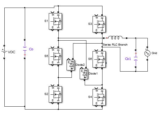
The grid connected PV system has drawback that the common mode voltage is not constant. This drawback can be eliminated by using H6 type inverter shown in Figure 1 instead of normal inverter [10]. Thus the common mode voltage is maintained by using PWM technique. By the use of H6 type inverter switching voltages across the switches is halved and switching losses are reduced [11].
|
| Figure 1. H6 type inverter |
2. Design interleaved flyback converter
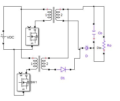
The interleaved flyback converter shown in Figure 1 has four modes of operations. During first mode the current flows through the switch SW. During second mode the current flowing through switch SW1 and other switch is off. During third mode because of transformer magnetization, the diode is forward biased and gets the output and during fourth mode the second transformer magnetized and gets the output [12].
|
| Figure 2. Interleaved flyback converter |
The output voltage of flyback converter is obtained from expression
|
|
where is Duty cycle, and is High frequency transformation ratio, , .
3. Modes of operation
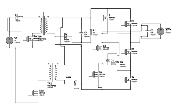
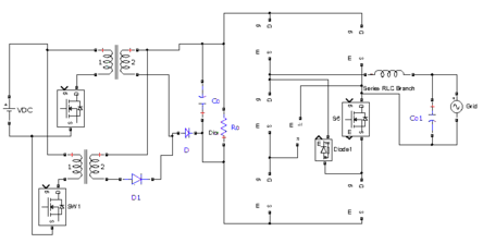
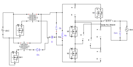
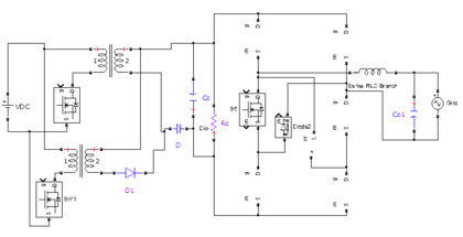
The proposed interleaved flyback converter with H6 type inverter for PV application shown in Figure 3 consist of boost flyback converter and single phase H6 type inverter. The operation of proposed system is explained by four modes.
|
| Figure 3. Interleaved flyback converter with H6 inverter |
| Mode 1: Active mode |
|
| Mode 2: Freewheeling mode during positive half cycle |
|
| Mode 3: Active mode |
|
| Mode 4: Freewheeling mode during positive half cycle |
|
4. Simulation results and discussion
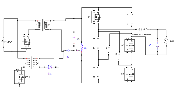
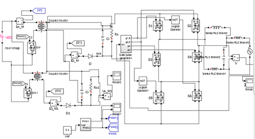
The simulation is carried out to get an idea of interleaved flyback converter with H6 type inverter. The simulation is carried out in MATLAB/ Simulink software as shown in Figure 4, and corresponding control signal generation blocks with PLL loop is described in Figure 5. The maximum power point tracking is not given much importance. The grid side voltage is taken as reference and fed to phase locked loop to get a sinusoidal signal which is then fed to PI controller and with this a pulse signal to H6 type inverter is obtained.The simulation results shown in Figure 6 generation of PWM signal fed to drive interleved fluback converter based phase locked loop and output volatges and current. Different modes of boost shown in Figure 7 with filter and without filter for linear and non-linear loads.
|
| Figure 4. Proposed flyback with H6 inverter |
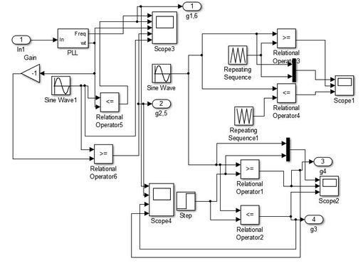
|
| Figure 5. PLL PWM generation |
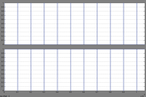
|
| Figure 6. |
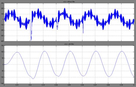
|
| Figure 7. Output with filter and without filter |
5. Experimental verification
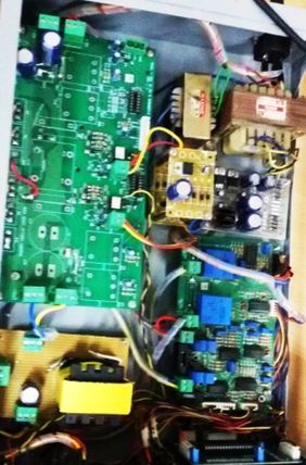
To validate the effectiveness of the proposed converter, a prototype model is built as shown in Figures 8(a) and (b). The converter parameters are set as per simulation model in developed converter as listed in Table 1.

|
| (a) |
|
| (b) |
| Figure 8. (a) Photographs of solar PV source in roof top. (b) Details of the proposed converter |
| Parameter | Value |
|---|---|
| Capacitor | 100e-6 Farad |
| Resistance | 100 Ohm |
| Inductance | 0.8e-3 Henry |
| Grid voltage | 230 Volt/ 50 Hertz |
| Input voltage | 100 Volts/DC |
| Output voltage | 350 Volts/ AC |
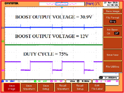
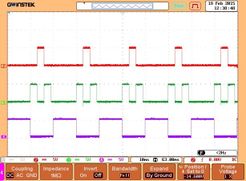
The switching frequency of proposed converter set to operate at 500 kHz and obtain zero voltage through PWM switching technique.The PV cell output fed to proposed converter further the carrier and reference signal is compared based on inputs side to side from the hall-effect sensor obtains the signal carrier and reference signal is compared and pulse generated to drive proposed converter to transfer power from converter to grid. The conventional flyback converter output voltages are 22 V for 25%, 23.6 V for 50% and 30.9 V for 75% duty cycles from the input of 12V as shown in Figures 9(a) and (b).
|
| (a) |
|
| (b) |
| Figure 9. Waveforms of conventional flyback converter |
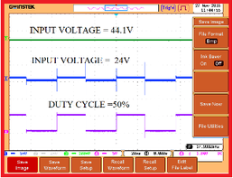
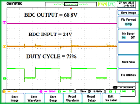
The proposed converter obtained output voltages are 30.3V for 25%, 44.2V for 50% and 24V for 75% duty cycles from the input of 24V as shown in Figure 10 and detailed parameters comparison made available in Table 2.
|
| (a) |
|
| (b) |
| Figure 10. Waveforms of proposed converter operating modes |
| Parameter | Fly back Interleaved Converter | Proposed Converter |
|---|---|---|
| Input Voltage | 5-100 V | 5-220 V |
| Maximum Output Power | 45 Watts | 60 Watts |
| Switching frequency | 25-200 kHz | 100 -500 kHz |
| Max. Efficiency | 89.1% | 92.6 % |
| Inductance Energy recovery | Low | High |
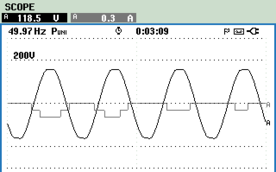
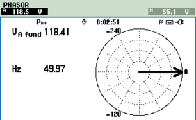
Further the switching stress on PWM switches is reduced with compared with conventional flyback converter and proposed interleaved converter with results as shown Figure 10. Reduced voltages stress and better in interleaved converter side enhances the performance in inverter side fed to grid due to H6 inverter topology with less spikes fed to load through grid as shown in Figure 11.
|
| (a) |
|
| (b) |
| Figure 11. Performance of power fed to grid from proposed converter |
The performance comparisons of proposed interleaved flyback converter with H6 inverter configuration and flyback converter are registered through Table 2. In aspects of power handling capability and efficiency is improved under various load conditions due of the proposed H6 inverter techniques proposed with flyback converter technique.
6. Conclusion
In this paper the interleaved flyback converter and H6 type inverter are incorporated and simulated using MATLAB software to verify that the voltage stresses across the switches are reduced using RCD circuit and by using H6 inverter, voltage is maintained constant. The THD value is reduced by using PWM and filters. Further design procedure will be analyzed and the real performance of the proposed system will implement by prototype. The proposed converter with H6 inverter topology with interleaved boost converter is designed with less cost and modest structure and a useful application drive to interface between photovoltaic with loads with grid system.
References
[1] Pallavi M., Sravan Kumar S.L.V, Reddy N.R.. An integrated boost parallel flyback converter for multi load applications. International Journal of Innovative Technology and Exploring Engineering, 8(4S2):42-48, 2019.
[2] Seelam S., Kumar G.R., Rao N.S., H6 Transformer less topology and its modulation strategy for mitigating Cm currents in Pv grid connected inverters. Journal of Engineering Research and Applications, 5(8):46-51,2015.
[3] Das A., Sheeja G. Single-phase H6 transformerless inverter with a simple boost converter for PV-grid tied power systems. International Journal of Research in Engineering and Technology, 04(6):318-323, 2015.
[4] Mohammadi M., Adib E. Lossless passive snubber for half bridge interleaved flyback converter. IET Power Electronics, 7(6):1475–1481, 2014.
[5] Kim Y.H., Ji Y.-H., Kim J.-G., Jung Y.-C., Won C.-Y. A new control strategy for improving weightedefficiency in photovoltaic AC module-type interleaved flyback inverters. In IEEE Transactions on Power Electronics, 28(6):2688-2699, 2013.
[6] Ryu D.K., Kim Y.-H., Kim J.-G., Won C.-Y., Jung Y.-C. Interleaved active clamp flyback inverter using a synchronous rectifier for a photovoltaic ac module system. 8th International Conference on Power Electronics - ECCE Asia, pp. 2631-2636, May 2011.
[7] Zhang J., Huang X., Wu X., Qian Z. A high efficiency flyback converter with new active clamp technique. In IEEE Transactions on Power Electronics, 25(7):1775-1785, 2010.
[8] B. Sun, R. Burgos, and D. Boroyevich, Ultralow input–output capacitance PCB-embedded dual-output gate-drive power supply for 650 V GaN-based half-bridges. IEEE Trans. Power Electron., 34(2):1382–1393, 2019.
[9] Park J. et al. Quasi-resonant (qr) controller with adaptive switching frequency reduction scheme for flyback converter. IEEE Trans. Ind. Electron., 63(6):3571–3581, 2016.
[10] Murali M., Arulmozhiyal A., Sundara Moorthy P. A design and analysis of voltage source inverter for renewable energy applications. Telkomnika Indonesian Journal of Electrical, 27-4:36-45, 2014.
[11] Murali M., Arulmozhiyal R. Investigation on Solar PV generation and design of switched reluctance motor for Smart Agriculture actuation system. Brazilian Archives of Biology and Technology, 61:e18160767, 2018.
[12] Wang C.-M. A novel ZCS-PWM flyback converter with a simple ZCS-PWM commutation cell. IEEE Transactions on Industrial Electronics, 55(2):749-757, 2008.Document information
Published on 05/10/22
Accepted on 11/09/22
Submitted on 14/07/21
Volume 38, Issue 4, 2022
DOI: 10.23967/j.rimni.2022.09.006
Licence: CC BY-NC-SA license
Share this document
claim authorship
Are you one of the authors of this document?