ABSTRACT
We present recent developments in the coupling of the finite element method (FEM) and the discrete element method (DEM) for analysis of rock blasting operations in tunnels. The coupled FEM-DEM technique has proven to be an efficient technique for predicting the multi-fracture of rock induced by the loads generated in blasting situations.
The coupled FEM-DEM procedure is applied in the tunnel construction, as well as to gas pressure blasting pyrotechnics situations to break rock for excavation of the tunnel front. In the latter case the effect of gas explosion is modelled by solving with the FEM the equations of gas dynamics in the analysis domain. The effect of the gas forces in the underlying rock mass is modelled with an embedded fluid-structure interaction method. This allows us to accurately predicting the progressive multi-fracture of the rock accounting for the penetration of the gas in the fractured domain modelled with the FEM-DEM procedure.
The efficiency of the coupled FEM-DEM technique is demonstrated in several examples of fracture tests and rock blasting problems related to tunnel engineering. The examples presented show that the combination of the DEM with simple 3-noded linear triangular elements correctly captures the onset of fractures and their evolution [1].
1 INTRODUCTION
The FEM-DEM procedure is based on an initial discretization of the analysis domain by a mesh of standard finite elements (FE). Onset of fracture at a point is governed by a simple damage model. Once a crack is detected at an element side in the FE mesh, discrete elements (DE) are generated at the nodes sharing the side. A simple DEM approach is used to model the evolution of the crack in the fractured solid [4-6]. This optimizes the use of DE to zones where they can be more effective, which considerably simplifies the contact search process and reduces the overall computational cost.
In this paper we use two approaches to simulate the pressure-time behavior of an explosion: a) The direct application of the well known pulse function, and b) A computational fluid dynamics (CFD) code coupled to a solid mechanics code using the embedded mesh approach in order to identify the fluid domain.
2 BASICS OF THE IMPLEMENTATION
2.1 FEM/DEM approach
We solve the solid domain, using an implicit dynamic approach of the equilibrium equations. In essence, the adaptive DEM-FEM procedure starts with a discretization of the analysis domain using a FE mesh only and operates as follows:
1. At each time instant verify the stress levels at each element. For linear triangles and tetrahedra this simple implies computing the strains and stresses at the middle point of the element sides. This strategy corresponds to the superconvergent patch recovery [2]
2. Evaluate the threshold of failure (fracture) of each element. This can be done via procedures based on the point-wise value of the stresses (or the strains), or using an adequate energy norm. In our work a simple Rankine model with a linear damage model has been used to define the onset of fracture at the element sides [3]. The element damage corresponds to the largest value of the damage at the different cut planes existing in a triangle. The cut plane damage is evaluated as the mean damage of the edges involved in such cut plane as shown in Figure 1a, were two sides are damaged.
3. Introduce a collection of DE within the FE that have exceeded the failure threshold. In our work this occurs when the element damage reaches a value of 95% At this moment, the continuum region previously occupied by the FE is now modelled with a collection of DE created at the element nodes and the damaged elements are removed (Figure 1b). The radius of the new DE is defined as the maximum possible to avoid collisions with other DE.
4. A two-stage time integration is used to solve the contact between the DE and the FE mesh. For the DE an explicit scheme is used to record the impulse between t and t + Δt [7,8]. The impulse found is used in the FE mesh, in order to evaluate the displacements, velocities and accelerations in the DEs at the same time period via an implicit time integration scheme.
The introduction of additional DE regions on the FE mesh evolves in time accordingly to the evolution of the stress field in the domain. For blast problems the transition of the FE mesh to the DE region occurs quite rapidly, as the fracture zone progresses almost at the blast speed on the whole analysis domain. The adaptive FEM-DEM procedure is still effective in these cases as the time increment for the explicit solution is very small and the delay in introducing DE leads to considerable savings in computing time [1,7,8].
2.2 Pressure simulation
In order to characterize the explosion two different approaches have been used. The simplest one corresponds to the classical pressure-time function wide used in the literature [9-11] which expresses the pressure as an exponential function of the time where the parameters used try to reproduce the characteristic print of the most popular explosives.
The amplitude and the duration of the pressure wave can be determined by the internal energy of the explosive and the size and geometry of the borehole. To represent a large range of borehole pressures, the following general form of a pulse function is used [10],
| (1) |
where P is the pressure at time t, P0 is the peak pressure, and α and β are constants. The pressure-time curves for α/β = 2.0 used in this work are presented in Figure 2.
Even if this approach works fine for many examples, sometimes is difficult to characterize properly the pressure-time curves for all the possible explosives used. Also it is impossible to consider the space created by the cracks and its interaction with the gases generated by the explosion. In this context a CFD code developed in an explicit time integration scheme has been used with the Jones-Wilkins-Lee (JWL) equation of state (EOS) for the pressure [12,13].
The main problem in this case is not to solve the classical fluid dynamic equations with the corresponding EOS, but to define properly the fluid domain. The crack propagation changes dramatically this domain and an efficient technique is needed to update it. In our work we have used an embedded solution technique for this purpose.
The embedded surfaces can be treated by applying contour kinematic conditions at the nodes located in the vicinity of the cracked surface. Depending on the accuracy there are first and second order approximations. In our work a second order approach is used [14,15].
The boundary between the embedded fluid domain and the solid one can be found by performing an element by element search, deactivating the fluid nodes outside this boundary. New nodes are created at the intersected edges which increases the memory requirements but simplifies the needed conditions to be imposed at the boundaries. In general, these conditions are imposed in a direct way interpolating at the new nodes the values of the displacements, velocities and pressure at the inner domain.
3 EXAMPLES
Many examples in 2D and 3D have been performed in order to verify the consistency of the FEM-DEM formulation used, all of them with excellent results [1]. Herein some examples related to blasting problems are described in order to show the usefulness of the FEM-DEM procedure.
3.1 Pressure loading rate effect
It is well known that mechanical properties of rock materials are affected by the strain rate, this effect has a big influence in the rock fracture pattern. Higher strain rates produce a crushed zone and short fractures while lower strain rates produce a small crushed zone and fewer and longer radial fractures [9,11].
To verify these observations of the strain rate effect, two different waveforms of the blast loading have been numerically simulated and compared with the literature results [16]. Fig. 2 shows the pressure–time record used for the numerical simulation. The 2D model consists of a borehole (ϕ= 0.005m) in a circular rock mass (ϕ = 0.140m) modeled with 35,046 elements. The material properties are E= 21.0 GPa, υ = 0.22, γ = 25,000 N/m3, thickness = 0.1 m, σt = 5.23 MPa and G = 22 J/m2. The pressure rising time t0 varies between 5 and 100 µs. The peak pressure is kept constant to 100 MPa. while the loading rates are 20, and 1.0 MPa/µs, respectively.
The simulated fracture patterns with different loading rates are compared in Fig. 2. When the loading rate of the pressure is high (20 MPa/µs), only a small crushed zone is created (Fig. 2a). The blast energy is primarily dissipated in creating the crushed zone. When the loading rate decreases to 1.0 MPa/µs, a central crushed zone and longer radial fractures appear as shown in Fig. 2b. The results agree with those reported in [9,11,16].
Figure 2: Effect of pressure loading rate. a) 20 MPa/µs loading rate. b) 1 MPa/µs loading rate. The graphs shows the two pressure curves used.
3.2 Open air quarry analysis
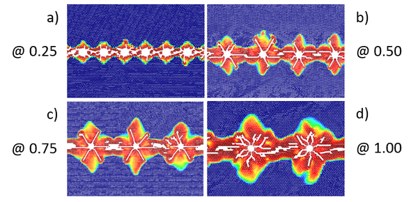
The geometry analyzed corresponds to a 4.0 x 6.25m 2D domain constrained in all its edges except the lower one. The cutting line was set at 1.0m from the free side. Different spacings of the boreholes (ϕ=0.175m) were analyzed (0.25, 0.50, 0.75 and 1.0m). The load pressure is defined as in curve (b) of Figure 2. The material properties are E= 10 GPa, υ = 0.2, γ = 78,000 N/m3, thick = 1.0 m, σt = 0.10 MPa and G = 100 J/m2.
Figure 3: Open air quarry analysis. Damage zone and cracks around the boreholes. Four different spacings are shown.
The results obtained show a clear correlation (> 90%) of the width of the damaged zone respect the borehole spacing, which goes from 0.2m for the 0.25m spacing up to 0.6m for 1.0m spacing, as shown in Figure 3. This results are the expected ones and confirm the good behaviour of the FEM-DEM simulation.
3.3 “Aguas teñidas” tunnel front
“Aguas teñidas” is a mine located in the province of Huelva, Spain. It is a conformant sulfide deposit of the Iberian Pyrite Belt. This mine produces copper and polymetallic. The exploitation is carried out using mainly conventional drilling equipment for blasting.
A front blasting sequence is analyzed with the pressure rising time of 100 µs. and a peak pressure of 100 MPa. The material properties correspond to E= 10 Gpa, υ = 0.2, σt = 0.10 MPa and G = 100 J/m2.
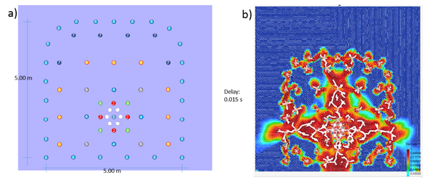
The tunnel front has 57 boreholes classified in 8 blasting groups as shown in Figure 4a. The blasting delay is 15 µs between each group. No initial pressure is applied at the rock mass; it means that the tunnel is simulated at a very low deep. On Figure 4b the damage at the final time analysis is presented. It is remarkable the sub-excavation at the base of the tunnel which matches the real problem. The horizontal damage zone is due to the zero initial pressure in the rock mass.
Figure 4: Aguas Teñidas tunnel front. a) Blasting sequence. b) Crack and damage pattern.
3.4 Coupled fluid-blast-crack problem
A preliminary example is shown for the coupling solution between the cracking in a square solid rock mass and the CFD analysis in which the explosive state equations are solved. The example corresponds to a 2D granite rock sample of 0.2 x 0.2m and a borehole of ϕ = 0.02m. The explosive used corresponds to a C4 kind. Besides the simplicity of the example, it proves the usefulness of coupling fluid-blast-cracking scheme proposed.
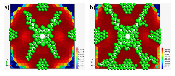
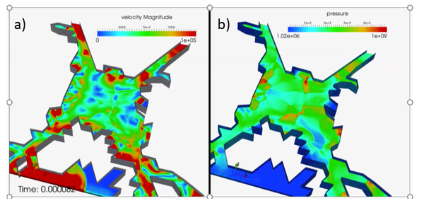
In Figure 5 the cracks and damage zone corresponding at two different times (0.041µs and 0.082 µs) are presented. The cracked domain is pass to the CFD solver each time step in order to compute the pressure evolution which is returned to the mechanical FEM-DEM solver.
Figure 5: Damage zone and cracks on the specimen at a) 0.41µs and b) 0.82 µs.
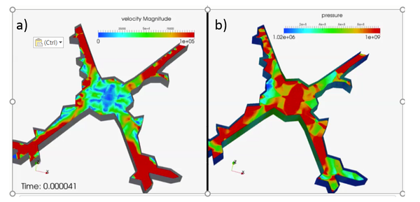
Figures 6 and 7 shown the CFD results for the same times. Figure (a) displays the fluid velocity and Figure (b) the pressure evolution. We highlight the shockwaves produced by the explosion within the fluid domain.
Figure 6: a) Velocity and b) pressure distribution in the fluid domain at 0.41µs.
Figure 7: a) Velocity and b) pressure distribution in the fluid domain at 0.82 µs.
4 CONCLUSIONS
A simple FEM-DEM methodology has been presented for reproducing the cracking pattern in rock blasting problems. The good results obtained demonstrate that the FEM-DEM technique an efficient and promising procedure for solving rock excavation and blasting situations in tunnels.
The effect of the gas forces in the underlying rock mass is modelled with an embedded fluid-structure interaction method. This allows us to accurately predicting the progressive multi-fracture of the rock accounting for the penetration of the gas in the fractured domain modelled with the FEM-DEM procedure described.
ACKNOWLEDGEMENTS
The authors acknowledge the financial support of the VOLADAPT project co-funded by the Spanish Ministry of Science and Innovation. (2014-2016) via the subprogram RETOS COLABORACIÓN (RTC-2014-2237-5)
REFERENCES
[1] Zárate F., Oñate E. A simple FEM-DEM technique for fracture prediction in materials and structures. Computational Particle Mechanics 2015; 2(3): 301-314
[2] O.C. Zienkiewicz O.C., Zhu J.Z., The superconvergent patch recovery (SPR) and adaptive finite element refinement. Comput. Methods in Appl. Mech. Eng 1992; 101,(1–3): 207-224
[3] Cervera M., Chiumenti M., Codina R. Mesh objective modelling of cracks using continuous linear strain and displacements interpolations. Int. J Num. Meth. Eng. 2011, 87:962–987
[4] Labra C., Rojek J., Oñate E., Zarate F. Advances in discrete element modelling of underground excavations. Acta Geotech 2009, 3(4):317-322.
[5] Oñate E., Zarate F., Miquel J., Santasusana M., Celigueta M.A., Arrufat F., Gankikota R., Valiullin K. and Ring L. A local constitutive model for the discrete element method. Application to geomaterials and concrete. Computational Particle Mechanics. 2015 2(2):139–160.
[6] Oñate T., Rojek J. Combination of discrete element and finite element methods for dynamic analysis of geomechanics problems. Comput. Methods Appl. Mech. Eng. 2004 193:3087-3128.
[7] Rojek J., Oñate E. Multiscale analysis using a coupled discrete/finite element model. Interact. Multiscale Mech, 2007 1(1):1-31.
[8] Labra C., Oñate E., Zárate F., Rojek J. Modelling and simulation of the effect of blast loading on structures using an adaptive blending of discrete and finite element methods Particle-based methods II: fundamentals and applications: proceedings of the II International Conference on Particle-based Methods 2013, 457-465
[9] Donze FV, Bouchez J, Magnier SA. Modeling fractures in rock blasting. Int J Rock Mech Min Sci 1997;34(8):1153–63.
[10] Cho SH, Kaneko K. Influence of the applied pressure waveform on the dynamic fracture processes in rock. Int J Rock Mech Min Sci 2004;41:771–84.
[11] Cho SH, Ogata Y, Kaneko K. Strain rate dependency of the dynamic tensile strength of rock. Int J Rock Mech Min Sci 2003;40:763–77.
[12] Kury J.W., Lee E.L., Hornig H.C., McDonnel J.L., Ornellas D.L., Finger M., Strange F.M. and Wilkins M. L., Metal Acceleration by Chemical Explosives, Fourth Detonation Symposium 1965: 3–13.
[13] Lee E.L., Hornig H.C. and Kury J.W. Adiabatic Expansion of High Explosive Detonation Products, Technical Report 1968, LLNL, UCRL-50422.
[14] Löhner R., Cebral J.R:, Camelli F.E., Appanaboyina S., Baum J.D., Mestreau E.L., A. Soto O.A. Adaptive embedded and immersed unstructured grid techniques, Comput. Methods in Appl. Mech. Eng 197, (25–28) 2173-2197, 2008
[15] Löhner R., Baum J.D., Mestreau E, Sharov D., Charman C., Pelessone D. Adaptive embedded unstructured grid methods Int. J. Numer. Meth. Eng. 2004, 60 (3): 641–660
[16] Ma G.W., An X.M. Numerical simulation of blasting-induced rock fractures. Int. J. Rock Mech. Min. Sci 2008: 45: 966–975
Document information
Published on 01/01/2018
DOI: 10.1016/j.undsp.2018.09.002
Licence: CC BY-NC-SA license
Share this document
Keywords
claim authorship
Are you one of the authors of this document?


