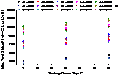
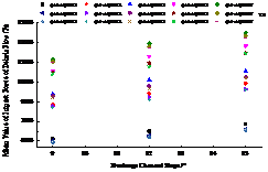
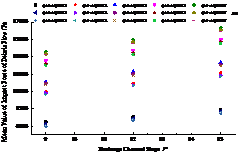
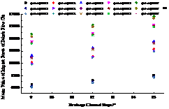
Abstract: The impact force of debris flow is not only an important indicator of the risk assessment of debris flow and the strength impact resistance of buildings against debris flow, but also an important parameter in the design of various debris flow prevention projects (such as the check dam and the drainage channel, etc.). The pressure sensors are arranged at different positions (monitoring points) on the upstream face of the check dam. By changing the slope of the drainage channel, the bulk density of debris flow and the slope gradient of the upstream face of the check dam, the time history curves of the impact force at the monitoring points under different experiment conditions are obtained. The characteristic value of impact force of debris flow acting on the surface of sand retaining dam is analyzed, and the evolution law of mean value and maximum value of impact force of debris flow at the same detection location with the above conditions is obtained. The mean value and maximum value of debris flow impact force at dif-ferent detection locations under the same working condition are analyzed to obtain the evolu-tion law of debris flow impact force at different locations, and then the distribution trend of debris flow impact force on the upstream face of the check dam is obtained. The research results provide scientific and reasonable theoretical basis and technical support for the stability analysis of the check dam, so as to better serve the disaster prevention and reduction of debris flow, which will improve the technical level of the debris flow prevention project to a certain extent.
Keywords: Debris flow impact force; Dynamic response; Drainage channel slope; Debris flow bulk density; Check dam
1. Introduction
Debris flow refers to a special torrent that carries a large amount of sediment and stones due to landslide caused by rainstorm, snowstorm or other natural disasters in mountain areas or other deep ravines and steep terrain areas. Debris flow contains a large number of mud, sand and stones, and are characterized by sudden outbreak, short duration, great destructive power, unpredictable, intense attack, and serious erosion and deposition. Debris flow has great harm, which not only inundates farmland, raises riverbed and causes environmental pollution, but also blocks river courses and submerges villages in serious cases, threatening the lives of people and property safety. The destruction of water conservancy and hydro-power projects, bridges, roads and communication facilities has brought a devastating blow to the already fragile ecological environment and economic development in mountainous areas. The construction of debris flow control project in the upstream can effectively reduce the harm of debris flow to downstream life and buildings. The damage of debris flow to buildings (structures) is mainly impact in the positive direction and mainly siltation and friction in the lateral direction. The impact force of debris flow is one of the main ways to cause the destruction of buildings (structures) in the area affected by debris flow [1]. Therefore, the design of debris flow prevention and control projects, such as debris flow check dams, drainage channels, bridges and other infrastructure, need to estimate the debris flow impact force in advance. At present, there is no debris flow impact force model that is fully applicable to engineering design, accurate enough and can be directly used for calculation [2]. Most of the debris flow impact calculation models used in engineering design are empirical or semi empirical formulas. A load that can be contacted along the way during the flow process of debris flow, such as buildings and structures, which changes with time and space, is called debris flow impact force [3, 4]. It is the main external force for the destruction of roads, bridges, houses and retaining works in debris flow area, especially the local impact failure of large stones. Debris flow is a typical solid-liquid two-phase flow. The particle size distribution of solid particles carried by debris flow during movement ranges from a few millimeters to tens of meters, resulting in the difference of impact force of debris flow under different working conditions, which is difficult to be explained by density, velocity and mud depth [5]. At the same time, due to the randomness of solid particle impact, the debris flow impact force obtained at different locations under the same working condition is also different [6], which further increases the difficulty of studying the debris flow impact force. For many years, the determination of debris flow movement characteristics and impact load has been a key problem perplexing the scientific development of debris flow and a difficulty in the study of debris flow mechanics [7, 8]. The main ways to obtain the impact force data of debris flow include field measurement, indoor model experiment and numerical simulation.
1.1 Field measurement
The impact measurement of field prototype debris flow is an important means to obtain reliable data. Okuda et al. [9] used strain gauge and indentation gauge installed on the dam to observe the debris flow impact force at Shaoyue mountain gully debris flow observation station. Zhang Shucheng et al. [10] made long-term observation by taking advantage of the natural advantages of Jiangjia gully, a high-frequency debris flow gully in Yunnan, measured the impact force process line of debris flow, and preliminarily analyzed the characteristic value of impact force. Wu Jishan et al. [11] established debris flow impact piers and abutments in Jiangjiagou, Yunnan Province. Through sensors and microcomputer, the time history curve of debris flow impact force was obtained, and the debris flow impact load was generalized into saw-tooth pulse, rectangular pulse and peak pulse. Taking advantage of the natural advantages of Jiangjia gully in Dongchuan, Hu Kaiheng et al. [5] fixed the force sensor at different heights of the field observation device to receive the debris flow impact force, and obtained the original signals of debris flow impact force through the data acquisition system and relevant data processing software. What is more, these original impact signals have the characteristics of complete waveform, long duration and representing different mud depth positions. With the data processing program, the real impact force data of debris flow are obtained by noise reduction. König [12], wendeler et al. [13] carried out in-situ measurement of debris flow. In addition, denatale et al. [14] and Bugnion et al.[15, 16] carried out experimental study on large-scale debris flow respectively. The advantages of large-scale debris flow experiment or in-situ observation of debris flow impact force by monitoring station do not need to consider the scaling problem, and some important data can be obtained. However, the possibility of controlling boundary conditions for system data acquisition is limited. For example, the occurrence time and frequency of a debris flow are unpredictable. The installation and operation of measuring equipment are the main disadvantages of debris flow observation in natural ditches. For large-scale debris flow experiments, the expected material consumption will lead to high measurement cost, and the fluid and material parameters are often unpredictable [17].
1.2 Indoor model experiment
Based on the above reasons, a large number of scholars have carried out the experiment of debris flow impact force drainage channel on the basis of considering the scaling ratio, and conducted in-depth research on the impact force of debris flow. Taking the drainage channel as the experimental model, Wei Hong [18] carried out the experiment of the dam body impacted by the debris flow head, analyzed the composition of the peak value of the impact force, established the calculation formula of the impact force of the debris flow head, and obtained the vertical distribution law of the impact force when the debris flow impacted the dam body. The impact of debris flow on curved dam is studied [19]. Chen Hongkai [20-22] built a large-scale experimental model of debris flow gully, carried out a series of experiments on the impact characteristics of debris flow, studied the effects of slurry viscosity, solid particle size and solid ratio on the impact characteristics of debris flow, and obtained some useful conclusions. Yang et al. [23] studied the velocity and impact characteristics of debris flow, and obtained the quantitative relationship between the surface velocity and the surface impact force of debris flow through data analysis. Scheidl et al. [17] carried out the model experiment of debris flow impact characteristics, and obtained the maximum impact force of debris flow through the analysis of experimental data. Tang Jinbo et al. [24] took the large-scale experimental drainage channel as the experimental model to carry out the impact force experiment of debris flow. Through wavelet analysis, the original signal of impact force was denoised. Meanwhile, it is found that the calculation formula of impact force of liquid slurry of debris flow. Bugnion et al. [25] measured the debris flow impact force with the debris flow impact model experiment, and obtained that the impact velocity of debris flow is 2~13 m/s. Song et al. [26] discussed the longitudinal distribution characteristics of impact force when mixed fluids with different solid volume fractions act on rigid retaining dam through geotechnical centrifuge model test. With the increase of solid volume fraction in the fluid, the action mechanism of rigid dam is that the process of scouring and climbing is transformed into the process of particle accumulation and sedimentation, which reflects the change of impact mechanism caused by particle effect, and the climbing process also affects the temporal and spatial distribution of debris flow impact force. Choi et al. [27] studied impact characteristics and scouring mechanism of water and uniform solid particles acting on rigid dam body, and explained scouring and climbing mechanism and accumulation and silting mechanism of solid particles under water flow. Cui Peng, Zeng Chao et al. [28-30] arranged pressure sensors along different heights of the pillars. Water, debris flow paste, water-rock flow and full-scale debris flow were used to carry out impact force tests respectively. Through wavelet noise reduction and data analysis of the original impact signal, the distribution rule of mean impact value of debris flow along the height of the pillars was obtained and the impact frequency of solid particles was studied. Yu et al. [31] proposed an analysis method for debris flow impact signal processing based on empirical mode decomposition. Liu Daochuan et al. [32] carried out a series of debris flow experiments to study the influence of debris flow density on impact force. Wang Youbiao [33] carried out debris flow impact pier model test, and studied impact force of debris flow from two aspects: macro rheological model and micro stress component. Liang Heng et al. [34] established physical model based on flume test and simulated three-dimensional dynamic evolution process of debris flow impact pier with different rheological parameters and severity. Valentino et al. [35] firstly carried out the particle flow channel experiment, and then simulated the experiment with the help of the discrete element software PFC2D system, and obtained the characteristics of particle flow flushing distance and impact force spectrum. Huang Yu etal. [36][37] independently designed a large physical flume model test device to repeatedly reproduce the flow and impact process of debris flow.
Most of the above tests, whether indoor drainage channel test, large-scale debris flow impact test or field observation, are aimed at measuring impact force at some local control points, so it is difficult to obtain the time-space distribution data of impact force within the whole dam body.
1.3 Numerical simulation
Wang Xiuli et al. [38-41] analyzed the dynamic response of new debris flow retaining structure, new type of steel grid dam with spring support and steel structure under the action of debris flow and impact of large rocks by using finite element calculation software ANSYS, and obtained some beneficial conclusions, which provided important basis for the prevention and control of debris flow engineering. Yang Lu et al. [42] carried out dynamic response research on protective structure of shed tunnel under impact of rolling stones, obtained dynamic evolution law of contact force, displacement and energy of shed tunnel with time, analyzed impact angle and speed influence on Simulation results, and proposed a measure to reduce impact force of rolling stones-adding energy-dissipating shock absorber at support of shed tunnel. Su Jie et al. [43] used gabion arch retaining dam to solve the problem that the existing rigid retaining structure of debris flow was impacted and destroyed by debris flow, and carried out numerical simulation on its dynamic response to debris flow. The research results show that the flexible gabion arch structure optimizes the structural forces, enhances the structural deformation adaptive performance, and reduces the damage of fluid pressure of debris flow and impact force of large blocks to the structure. Liu Xingrong et al. [44] taking the debris flow check dam of Sanyanyu gully in Zhouqu, Gansu as an example, simulated the impact resistance of debris flow check dam based on incremental loading method. Liu et al. [45] provided a numerical model capable of reproducing estimates of debris flow effects by using coupled smooth particle hydrodynamics, discrete element method and finite element method to explain complex fluid-particle-structure interaction. Li Peizhen etal. [46] presented a novel masonry structure with strong resistance to debris flow—by using walls that are set with braces and filled with straw bricks. This structure was designed according to the concepts of sustainability. In order to study the dynamic response of this novel masonry structure under debris flow, finite element models of different masonry structures were established by means of LS-DYNA software. The responses of this novel structure and other traditional structures were calculated and compared when the rock of debris flow hits the center of the wall. Takebayashi and Fujita [47] developed a two-dimensional debris and mud flow model that considers both laminar and turbulence flow. Subsequently, the model was applied to a debris flow that occurred in Asaminami, Hiroshima, Japan in August 2014. Liu Xiao etal. [48] proposed an effective mathematical model for the assessment of impact pressure exerted by debris flows on obstacles. Chehade et al. [49]developed a numerical model to evaluate the impact pressure of mass flows, focusing on a better description of the influence of the blocks transported in these flows
The stability of check dam is the most concerned problem in the design of check dam control engineering, and the overall impact force of debris flow is the key factor affecting the stability of check dam. By changing the bulk density of debris flow, slope ratio drop of check dam and slope of drainage channel, the impact time history curve of debris flow at different monitoring points on the upstream face of check dam is measured, which provides certain data support for solving the stability problem of check dam. The data acquisition instrument adopts a high-speed continuous data acquisition instrument. Wavelet transform is adopted in the software part ofthe acquisitionsystem, which has better filtering effect on the sharp wimpacte noise signal in some time domain signals transmitted by the sensor. The soft-ware part of this acquisition system uses wavelet transform to reduce noise, which has a good filtering effect on some sharp wimpacte noise signals in some time domain signals from the sensor.
2. Experiment design
2.1 Experimental device
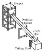
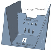
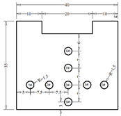
The experimental device is composed of drainage channel, check dam, hopper, tailings pond, camera, impact force sensor and data acquisition system. The experimental drainage channel is simplified to a rectangular section, and the specific dimensions are length × width × height = 8 m × 0.4 m × 0.4 m. The two sides of the drainage channel are made of tempered glass, what is more, the drainage channel and the hopper are fixed on the steel pipe support. The slope of the drainage channel can be adjusted according to the experiment, and the adjustment range is 0o ~ 15o. The dam body model is used together with the drainage channel model. The axial length of the dam body is 0.4 m, the upper bottom width is 0.2 m, the lower bottom width is 0.34 m and the height is 0.35 m. The upstream slope of the model dam is gentle and the downstream is vertical. The slope gradient of the upstream facing surface is 1:0.3, the overflow outlet width is 0.2m and the height is 0.05m. The back of the check dam is perpendicular to the bottom surface of the drainage channel, and the sensors are arranged on the upstream surface of the dam body. A camera is fixed above the check dam to record the impact phenomenon of debris flow impacting the check dam. The other two cameras are respectively placed behind the tailings pool and on the side of the discharge chute to record the movement process of debris flow. The volume of material required for every experiment remains the same, which is approximately equal to 0.5 m3. The volumes of hopper and tailings pond are respectively proposed to be 0.75 m3 and 1.85 m3.
The measuring instruments required for the experiment include three cameras, impact force sensor, data acquisition instrument, notebook computer, sampling bucket, water bucket, platform scale, steel ruler, balance, etc. The relevant technical parameters of impact force sensor and high-speed continuous signal collector are shown in Table 1. and table 2. The experimental model, experimental row guide channel, dam model and sensor layout are shown in Figure 1 to Figure 3.
| Specification | Accuracy
(%) |
Measuring Range (MPa) | Temperature Range
(℃) |
Power Supply
(DC) (V) |
Transmitter output Signal (V) | Appearance Dimensions (mm) |
| JNBP-6 | 0.1 | 0.6 | -30–70 | 20 | 0–5 | R=15, h=30 |
| Specification | Accuracy
(%) |
Analysis Bandwidth
(kH) |
Power Supply
(DC) (V) |
Output Signal | Appearance Dimension (mm) |
| JN-BSQ | 0.03 | 10 | AC220 | Digital signal | 220 |
| Channel Number | Sampling Method | Sampling Frequency (kHz) | A/D Converter | Operating Temperature (℃) | Noise
(dB) |
| 8 | Synchronous sampling | 20 | 16's column | -20–70 | 85 |
|
|
|
| Figure 1. Experimental model | Figure 2. Drainage channel and dam | Figure 3. Plane arrangement of pressure sensors (cm) |
2.2 Experimental materials
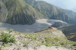
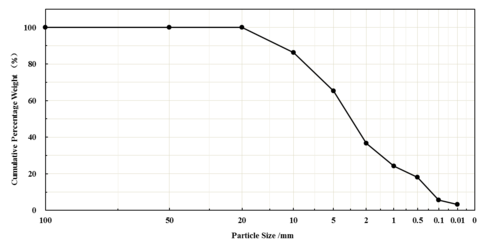
The test soil was taken from the debris flow channel of the Jiangjia Gully in Dongchuan because debris flows from this area are typical which were found in most of the mountainous regions in China (as shown in Figure 4). The particle size of the soil sample is 0–20 mm.. The particle size distribution of the soil sample is shown in Figure 5. The median particle size of the soil sample is 2.5 mm, and the contents of particles <1 mm and <0.1 mm are approximately 24.3% and 5.6%, respectively.
2.3 Design experimental conditions
Based on the factors affecting the impact force of debris flow, this paper ensures that the flow Q is equal to 0.5 m3 remains unchanged in every experiment. It mainly studies the impact characteristics of debris flow under the combination of different drainage channel slope, different debris flow bulk density and different upstream surface slope gradient of check dam. Three kinds of drainage channel slope, three upstream surface slope gradient of check dam and seven kinds of debris flow (water or stone flow) bulk density are analyzed by single factor, with a total of 45 experiment conditions. For the convenience of experimental research, the bottom surface of the check dam is parallel to the bottom surface of the drainage channel in the experiment, while the bottom surface of the check dam is parallel to the horizontal plane in the reference [50, 51]. The sum of the trough slopes is the value of the slope of the upflow surface of the check dam in reference [50, 51], and the range of slope ratio is [1:0.4, 1:0.8]. The slope of the drainage channel is recorded as A, the slope ratio of the upstream side of the check dam is recorded as B, and the bulk density of debris flow is recorded as C, then the test conditions can be written as AiBjCk, i=1, 2, 3; j=1, 2, 3 ; k=1, 2, 3, 4, 5, 6, 7. Among them: i=1, 2, 3 means that the slope of the drainage channel is 9o, 12o, 15o; j=1, 2, 3 means that the slope ratio of the upstream side of the sand bar is 1:0, 1:0.15, 1:0.30; k=1, 2, 3, 4, 5 means the bulk density of debris flow (water) is 10.0 kN/m3, 14.2 kN/m3, 15.5 kN/m3, 18.1 kN/m3, 19.5 kN/m3; k=6 indicates a water-stone flow with a particle size of 2-3.5 cm and a mass ratio of water to stone of 5:1; k = 7 means a water-stone flow with a particle size of 2-4.5 cm and a mass ratio of water to stone of 5:1 . For example, the working condition A2B3C4 indicates that the slope of the drainage channel is 12o, the slope ratio of the upstream side of the check dam is 1:0.30, and the bulk density of the debris flow is 18.1 kN/m3. A3B1C7 indicates that the slope of the drainage channel is 15o, the slope gradient of the upstream surface of the sand retaining dam is 1:0, and the particle size is 2 to 4.5 cm. The experimental design conditions are shown in the table 3.
| A | B | C | A | B | C | A | B | C | |||
| drainage channel slope /° | check dam upstream face slope | debris flow (water) density /kNm-3 | Particle size range water stone flow /cm | drainage channel slope /° | check dam upstream face slope | debris flow (water) density /kNm-3 | Particle size range water stone flow /cm | drainage channel slope /° | check dam upstream face slope | debris flow (water) density /kNm-3 | Particle size range water stone flow /cm |
| 9
|
1:0 | 10.0
14.2 15.5 18.1 19.5 |
2-3.5
2-4.5 |
12 | 1:0 | 10.0
14.2 15.5 18.1 19.5 |
2-3.5
2-4.5 |
15 | 1:0 | 10.0
14.2 15.5 18.1 19.5 |
2-3.5
2-4.5 |
| 1:0.15 | 10.0
14.2 15.5 18.1 19.5 |
2-3.5
2-4.5 |
1:0.15 | 10.0
14.2 15.5 18.1 19.5 |
2-3.5
2-4.5 |
1:0.15 | 10
14.2 15.5 18.1 19.5 |
2-3.5
2-4.5 | |||
| 1:0.30 | 10.0
14.2 15.5 18.1 19.5 |
2-3.5
2-4.5 |
1:0.30 | 10.0
14.2 15.5 18.1 19.5 |
2-3.5
2-4.5 |
1:0.30 | 10.0
14.2 15.5 18.1 19.5 |
2-3.5 2-4.5 | |||
3. Analysis of experimental results
3.1 Experimental phenomenon
3.1.1 Influence of debris flow density on deposition shape
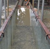
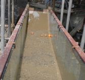
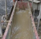
Figure 6 is a comparison chart of the deposition before the dam with different properties of debris flow. The results show that the coarsening of the dilute debris flow is relatively serious, a large number of stones are accumulated at the bottom of the drainage channel, and the slurry is separated from the stones. The viscous debris flow behind the dam is integrated with the block rock, and there is no water stone separation phenomenon. The accumulation of transitional debris flow before the dam is between dilute debris flow and viscous debris flow.
|
|
|
| dilute debris flow | b transitional debris flow | c viscous debris flow |
| Figure 6. Comparison chart of deposition in front of the check dam with different properties debris flow | ||
3.1.2 The Accelerated Motion Pattern of Debris Flow in the Drainage Channel
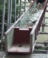
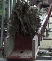
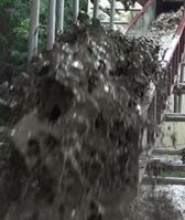
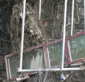
Figure 7 shows the front and side views of the movement process of the debris flow in the drainage channel. The results show that the entire movement process of the debris flow in the drainage channel can be divided into three stages: free motion acceleration stage, rushing collision stage, splashing landing stage.
|
|
|

|
|

|
| a. free motion acceleration stage | b. rushing collision stage | c. splash landing phase |
| Figure 7. Front and side views of movement process of debris flow in drainage channel | ||
3.2 Analysis of impact force characteristics of debris flow on check dam
3.2.1 Time-history curve of debris flow impact force
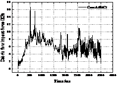
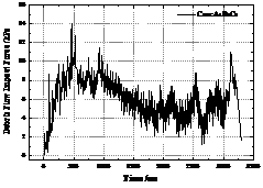
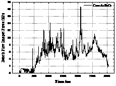
Taking the 3# sensor in the middle as an example, according to the impact load data on the up-flow surface of the sand dam under 4 types of debris flow bulk density and 4 working conditions collected by the high-speed continuous data acquisition instrument, the intercepted sensor receives the first impact force that is not 0 as the shock load between the starting point and the end point approximately equal to the static pressure. The time-history curve of the impact load of the sensor (3#) collected by the data acquisition instrument under different debris flow bulk densities is shown in Figure 8.
|
|

|
|
| Figure 8. Time-history curve of debris flow impact force | |
It can be seen from Figure 8 that the four debris flow conditions, the condition A1B3C5 (γc=19.5 kN/m3), has the shortest time to impact the sand bar, and the debris fluid accumulates in the drainage channel. The impact time of the other three working conditions is not much different. In Figure 8, both the 3rd and 4th graphs have an obvious peak due to irregular collision of large particles.
3.2.2 Variation law of eigenvalues of impact force with bulk density of debris flow
Taking the data of 3#, 5# and 8# pressure sensors measured by high-speed continuous data acquisition instrument as an example, this paper focuses on the evolution law of the maximum value, mean value and standard deviation of debris flow impact force with the bulk density of debris flow.
(1) Variation law of mean impact force with bulk density of debris flow
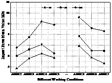
Taking A1B3Ck (k = 1 ~ 7) as an example, through probability statistics and analysis of the data collected by the data acquisition instrument, the mean value of debris flow impact force under seven test conditions is obtained, as shown in Table 4. At the same time, the evolution curve of the average impact force test value of debris flow with the bulk density of debris flow is given, and the average impact force value of dam surface obtained by formula (1) is listed on the curve, as shown in Figure 9. The mean value f of debris flow impact force represents the arithmetic mean value of N impact loads fi collected by the data acquisition instrument within time t, and its mathematical expression is:
|
|
(1) |
| Experimental conditions | A1B3C2 | A1B3C3 | A1B3C4 | A1B3C5 | ||||||||
| 5# | 3# | 8# | 5# | 3# | 8# | 5# | 3# | 8# | 5# | 3# | 8# | |
| Mean value of impact force test /kPa | 4.85 | 6.01 | 6.79 | 5.79 | 6.62 | 7.75 | 6.24 | 7.27 | 9.21 | 5.84 | 6.25 | 8.91 |
The calculation of the dynamic effect of debris flow slurry on buildings (structures) is generally based on the approximation of debris flow as an overall flow, which is obtained from the relevant theories of fluid mechanics. At present, most methods used to calculate the dynamic action of debris flow slurry are based on theoretical formulas. Change the relevant parameters for calculation, and its mathematical expression is shown in formula (2)[52, 53]:
|
|
(2) |
In the above formula, Fdy is the overall impact dynamic pressure of the mud-rock fluid, kPa; γc is the average gravity of the mud-rock fluid, kN/m3; vc is the average velocity of the mud-rock fluid, m/s; g is the acceleration of gravity, m/s2.
It can be seen from Figure 9 that from working condition A1B3C2 to working condition A1B3C4, the mean value of debris flow impact force shows a nonlinear increase trend with the increase of debris flow bulk density; from working condition A1B3C4 to working condition A1B3C5, the mean value of debris flow impact force shows a decreasing trend, mainly because the bulk density of debris flow increases, the viscosity coefficient increases, and the velocity of debris flow decreases. It can be seen from Formula (2) that the impact force of debris flow is positively correlated with the velocity and bulk density of debris flow. The mean value of impact force of debris flow decreases, which can be seen that the increase of viscosity coefficient has greater impact on the decrease of debris flow velocity than the increase of debris flow bulk density. At the same time, due to the small width of the test tank, the influence of boundary conditions is relatively large; the test scale is small, and the debris flow is small, resulting in a small mud depth, and the viscous debris flow of debris flow is not obvious. , which makes the impact force value smaller under the action of viscous debris flow. From working condition A1B3C2 to working condition A1B3C5, the mean value of the impact force of debris flow shows an increasing trend with the increase of bulk density. It can be seen that in these three working conditions, the influence degree of the decrease in velocity caused by the increase of viscosity coefficient is smaller than that of bulk density of debris flow. The A1B3C1, A1B3C6, A1B3C7 working conditions are mainly due to the existence of large solid particles, which hinder the water flow, so that the mean value of the impact force of the debris flow under the A1B3C6 and A1B3C7 working conditions is smaller than that of the A1B3C1 working condition.
(2) The evolution law of the maximum impact force with the bulk density of debris flow
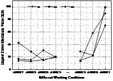
The maximum value of the debris flow impact force is an important factor for the local failure of check dam, and it is one of the important bases for the structural design of the check dam. In order to analyze the variation law of the maximum impact force of debris flow on the sand retaining dam with the bulk density of debris flow, the maximum value of the impact force of debris flow at different positions of the check dam under the experimental conditions is given. Figure 10 shows the maximum impact force of the debris flow on the check dam at different positions.
It can be seen from Figure 10 that under the test conditions, the maximum impact force of debris flow is not obvious due to the randomness of the impact of solid particles, and the maximum impact force of debris flow received by the check dam (3#, 5#, 8#) varies with the bulk density of the debris flow. When the particles do not impact the surface of the dam body or are not reflected by the sensor installed on the surface of the dam body, the maximum value of the impact is small; when the larger particles impact the surface of the dam body and are reflected by the sensor, the value of the impact force is large, 3# , 5# and 8# sensors all occurred in the A1B3C7 (water-rock flow composed of 2-4.5 cm) working conditions, and the maximum impact forces were respectively 99.277 kPa, 89.435 kPa, and 70.501 kPa. According to the change curve of the test value with the bulk density of debris flow, other external conditions are kept the same, and the randomness of particle impact is not considered assuming that the particles can impact the surface of the dam body and can be reflected by the sensors arranged on the surface of the check dam, the particle size is an important factor that affects the maximum impact force of debris flow.
3.2.3 Variation of characteristic value of impact force with the slope of drainage channel
According to the calculation formula of debris flow pressure, the flow velocity of debris flow is an important factor affecting the impact force of debris flow. According to the calculation formula of flow velocity, the slope of drainage channel (gully) is the main factor affecting the flow velocity of debris flow. Replacing the flow velocity formula of debris flow into the calculation formula of dynamic pressure force of debris flow, it can be seen that the slope of drainage channel (gully) is one of the decisive factors affecting the impact force of debris flow. Taking AiB3C5 (i=1~3) as an example, the variation curves of mean value, maximum value and standard deviation of debris flow impact force with the slope of drainage channel are analyzed.
(1) Variation of mean impact force with the slope of drainage channel
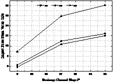
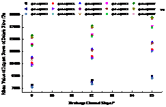
According to formula (1), the mean value of debris flow impact force at 3#, 5# and 8# sensor positions under three working conditions of AiB3C5 (i = 1 ~ 3) is obtained, as shown in Figure 11.
It can be seen from Figure 11 that the mean value of debris flow impact force received by the pressure sensors at 3#, 5#, 8# positions increases with the increase of the slope of the drainage channel, and the mean value of debris flow impact force at 8# position is the largest, followed by 3# position, and the mean value of debris flow impact force at 5# position is the smallest.
(2) Variation law of maximum impact force with the slope of drainage
channel
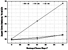
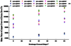
Taking AiB3C5 (i=1~3) as an example, the maximum impact force of debris flow at 3#, 5# and 8# sensor positions is given, as shown in Figure 12.
It can be seen from Figure 12 that the maximum impact force of debris flow received by the pressure sensors at 3#, 5#, 8# positions increases with the increase of the slope of the drainage channel. Because the solid particles are mostly concentrated at the bottom due to the blocking effect of the check dam, the maximum impact force of debris flow at 8# position is the largest, and the maximum impact force of debris flow at 3#, 5# position is relatively close.
3.2.4 Variation law of characteristic value of impact force with slope gradient
(1) Variation law of mean impact force with slope gradient of upstream surface of check dam
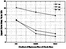
The impact of debris flow on sand retaining dam can be divided into frontal positive impact and inclined side impact with a certain angle. According to the reference [50], the slope side impact is generally reduced by multiplying the sinusoidal value of the impact angle of debris flow on the basis of the positive impact of debris flow on the front of the check dam. Taking A1BjC5 (j=1~3) as an example, this paper analyzes the impact of the upstream slope of the sand dam on the average impact force of debris flow by changing the upstream slope of the sand dam, as shown in Figure 13.
It can be seen from Figure 13 that as the slope gradient of the upstream surface of the sand retaining dam slows down, the average impact force of debris flow shows a decreasing trend, which is basically consistent with the reduction coefficient of the slope gradient of the sand retaining dam given in literature [50, 51]. At the same time, it can be seen that the average impact force of debris flow at 8# location is the largest.
(2) Variation law of the maximum impact force with the slope gradient of the upstream surface of check dam
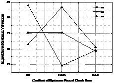
Taking A1BjC5 (j=1~3) as an example, the maximum impact force of debris flow at 3#, 5# and 8# sensor positions is given, as shown in Figure 14.
It can be seen from Figure 14 that as the slope gradient of the upstream surface of the check dam slows down, the variation law of the maximum impact force of debris flow is not obvious. The slope gradient of the maximum impact force of debris flow at 3# position is 1:0, while the maximum impact force of debris flow at 5#, 8# position is 1:0.15.
4. Numerical Calculation
4.1 Numerical simulation model and calculation parameter setting
4.1.1 Numerical simulation calculation model
Based on CFD commercial software FLUENT 14.0 and CSD calculation software ABAQUS, the interaction between debris flow and sand retaining dam is studied by taking the in-situ model as the prototype.
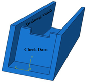
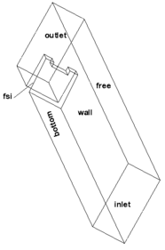
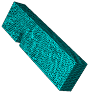
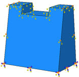
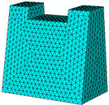
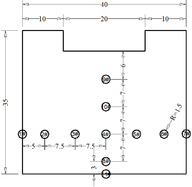
In order to further verify the reliability of the experiment results, the numerical simulation model established in this paper is basically consistent with the experiment model. The width of the row guide groove is 400 mm, the height is 400 mm and the length is 4000 mm. The height of check dam is 350 mm. The three-dimensional numerical simulation model of drainage channel and check dam is shown in Figure 15. Tetrahedral grids are used in both fluid domain and solid domain. The calculation model and grid division of fluid domain and solid domain are shown in Figure 16 and Figure 17. The layout of key points is shown in Figure 18. The rheology of debris flow refers to the relationship between the shear stress of debris flow fluid and the corresponding fluid rheological velocity gradient. At present, a large number of scholars have established many rheological models based on theoretical derivation and statistical analysis of experimental data. The most commonly used rheological models are [54-56]: Newton fluid model, Bingham fluid model, pseudo plastic fluid model, expansion body model, yield pseudo plastic fluid model, yield expansion body, etc. The relationship curve between shear stress and velocity gradient of various fluid rheological models is shown in Figure 19. A large number of test results show that the Bingham body rheological model of mud and stone fluid is more consistent with the reality[56]. According to formula (3-5) and relevant literature, it is necessary to know the fluid stiffness coefficient and yield stress when using Bingham fluid model.
|
|
|
| Figure 15. Schematic diagram of three-dimensional model of sand retaining dam and drainage guide groove | Figure 16. Three dimensional computational model and mesh generation in fluid domain | |
|
|
|
| Figure 17. 3D computing model and mesh generation in solid domain | Figure 18. Layout of key nodes (cm) | |
4.1.2 Calculation parameters
According to the characteristics of the numerical calculation software, the debris flow is simplified, and the size of debris flow solid particles is ignored to ensure that the density and characteristic parameters of debris flow are approximately consistent with the test materials. Wu Jishan et al. [52], Fei Xiangjun et al. [57], Kang Zhicheng et al. [58] summarized the calculation formulas of yield stress and rigidity coefficient of debris fluid on the basis of test. In this paper, Fei Xiangjun's formulas (3) and (4) are selected, and the yield stress and rigidity coefficient of debris flow under different densities are approximately obtained by referring to the calculation and test results of Dr. Zeng Chao's dissertation (the material is debris flow deposit of Jiangjia gully), as shown in table 5. The concrete constituting the sand retaining dam is regarded as an elastomer without considering its plastic development. The mechanical parameters of concrete materials are shown in Table 6.
|
|
(3) |
|
|
(4) |
In the above formula, η is the rigidity (viscosity) coefficient of debris flow, Pa . s. τy is yield stress of debris flow Pa . s. η0 indicates the viscosity coefficient of clean water. k indicates the concentration correction factor. Svf represents the original slurry concentration when coarse particles are not added. Svc is the concentration of coarse particles. Svm, indicates the limit concentration of coarse particles not added and added, as shown in the formula 5. Sv0 indicates the critical concentration of the suspension from Newtonian body to Bingham fluid,
|
|
(5) |
Where di and pi are the average diameter of a particle size group in the slurry particle grading curve and its corresponding weight percentage.
| Bulk density /kN/m3 | 14.20 | 15.50 | 18.10 | 19.50 | 10.00(water) |
| Yield stress /Pa | 0.276 | 0.511 | 3.936 | 11.450 | 0 |
| Rigidity coefficient /Pa·s | 0.0042 | 0.0066 | 0.018 | 0.037 | 0.0010 |
| Material | Density /kg/m3 | Elastic modulus /GPa | Poisson ratio | Tensile strength /MPa |
| Concrete | 2400 | 25.5 | 0.20 | 1.43 |
4.1.3 Boundary condition
The boundary condition of debris flow inlet is velocity inlet. Due to the influence of external conditions and debris flow itself, the velocity of debris flow flowing out of the hopper during the test is not controlled by legal person, and the velocity is unknown. Therefore, in the process of numerical simulation, it is assumed that the speed of each working condition is equal and does not change with time, the initial speed v = 5m / s and the inlet mud depth h = 8cm. Turbulence intensity I and turbulence length scale l are selected as turbulence characteristic parameters. The turbulence intensity I value is calculated by formula (6) and the l value of turbulence length scale is calculated by formula (8) [59]. The fluid outlet condition adopts free outflow. The free surface condition adopts the rigid cover assumption and is treated as the symmetrical surface, that is, the free slip surface. The wall condition is defined as no slip boundary. It is considered that the wall is uniform and the rough height Ks = 0.25 mm.
|
|
(6) |
|
|
(7) |
Where um indicates average velocity of section, m/s, h indicates mud depth, m and others are not in conformity with the contract.
|
|
(8) |
Where δ indicates boundary layer thickness. The simulation in this paper is the fully developed turbulent boundary layer thickness, =0.6H。
4.1.4 Analysis step settings
Computational fluid dynamics (ABAQUS) and computational structural dynamics (FLUENT) adopt the same analysis step settings, both of which are transient calculations. The number of analysis steps is set to 200 and the analysis step is 0.025 s.
4.1.5 Working condition design
At the initial time of calculation, the whole fluid calculation domain is filled with air, that is, the initial time is empty. An experimental model study is carried out on the interaction between debris flow and check dam from three factors: the slope of drainage channel, the slope gradient of upstream surface of check dam and the bulk density of debris flow. There are 45 working conditions in total. The expression method is similar to the design of experiment conditions. When the slope of the drainage channel is recorded as A, the slope gradient of the upstream surface of the sand retaining dam is recorded as B, and the unit weight of debris flow is recorded as C, the test condition can be written as AiBjCk, i=1, 2, 3; j=1, 2, 3; k=1, 2, 3, 4, 5. Where i = 1, 2 and 3 respectively indicate that the slope of row guide groove is 9 °, 12 ° and 15 °; j = 1, 2 and 3 respectively indicate that the slope gradient of the upstream surface of the check dam is 1:0, 1:0.15 and 1:0.30; k = 1, 2, 3, 4 and 5 respectively indicate that the unit weight of debris flow (water) is 10 kN/m3, 14.2 kN/m3, 15.5 kN/m3, 18.1 kN/m3 and 19.5 kN/m3. The design of numerical simulation conditions is shown in Table 7.
| A | B | C | A | B | C | A | B | C |
| Slope
/° |
Slope gradient of upstream face of dam | Bulk density of debris flow
/kNm-3 |
Slope /° | Slope gradient of upstream face of dam | Bulk density of debris flow
/kNm-3 |
Slope /° | Slope gradient of upstream face of dam | Bulk density of debris flow
/kNm-3 |
| 9
|
1:0 | 10.0
14.2 15.5 18.1 19.5 |
12 | 1:0 | 10.0
14.2 15.5 18.1 19.5 |
15 | 1:0 | 10.0
14.2 15.5 18.1 19.5 |
| 1:0.15 | 10.0
14.2 15.5 18.1 19.5 |
1:0.15 | 10.0
14.2 15.5 18.1 19.5 |
1:0.15 | 10.0
14.2 15.5 18.1 19.5 | |||
| 1:0.3 | 10.0
14.2 15.5 18.1 19.5 |
1:0.3 | 10.0
14.2 15.5 18.1 19.5 |
1:0.3 | 10.0
14.2 15.5 18.1 19.5 |
4.2 Result analysis
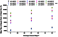
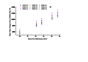
The variation trend of the mean value of total impact pressure of debris flow with the slope of drainage channel, the slope of upstream surface of check dam and the bulk density of debris flow is shown in Figures 20 ~ 22.
It can be seen from Figure 20 that the mean value of the total pressure at the key points (1#~4#, 8#~11#) on the upstream surface of the selected check dam increases with the increase of the slope of the discharge channel, and the change law is consistent with the test results.
It can be seen from Figure 21. that the average value of the total pressure at the key points (1#~4#, 8#~11#) on the upstream surface of the selected check dam decreases with the decrease of the slope gradient of the upstream surface of the check dam, and the change trend is consistent with the test results.
4.3 Comparison between numerical value and experimental results
Comparing the indoor experimental results and numerical simulation results of debris flow impact on the check dam, it can be seen that: because the boundary conditions and initial conditions are difficult to keep consistent, especially the velocity inlet boundary, the numerical simulation process assumes that the velocity v is constant, and the size of each working condition is unchanged. However, due to the different nature of the debris flow, the inlet velocity must be different, and the velocity changes with time, which will lead to different test results and numerical simulation results. What is more, the variation trend of the impact pressure of the debris flow is consistent with the slope of the drainage channel and the slope gradient of the upstream face of the check dam, and basically consistent with the change trend of the volume weight of the debris flow (except viscous debris flow). In addition, due to the impact of solid particles in the experimental process, and the limitations of numerical simulation software and researchers' level ignore the impact of particles, which will lead to a certain gap in the results.
5. Research conclusions
(1) According to the time history curve of debris flow impact signal, the debris flow impact signal under the test condition of this study is mostly serrated distribution, and a few are peak type.
(2) According to the time history curve of debris flow impact signal and with the help of Excel and other data processing software, the characteristic values such as the maximum value and average value of debris flow impact force are obtained. Due to the randomness of the impact of solid particles in debris flow, the variation law of the maximum impact force of debris flow with the above influencing factors is not obvious.
(3) Numerical study of the experimental model of fluid solid coupling between debris fluid and check dam is carried out. The variation trend of debris flow impact force with the slope of upstream surface of check dam, the slope of discharge guide groove and the bulk density of debris flow under the cooperation of fluid solid coupling is obtained. The numerical simulation results are consistent with the variation trend of indoor test results.
6. Discussions
(1) In view of the complex material composition of debris flow fluid and the great chance of solid particles in debris flow impacting on the sensor, the data collected by the data acquisition instrument changes greatly. The impact modes of debris fluid on the sensor are also different. Some faucets impact on the front, some faucets impact after they rise, and some faucets impact with the spray splashed by the faucet, which will affect the characteristic value of impact force. Under the impact of debris flow, the dam itself will produce a certain small deformation, which will have a certain impact on the test results, but the impact of dam deformation on the test results is not considered in the test process. The deformation and movement of the dam itself play a buffer role, which will lead to smaller experimental results; However, since the dam body is generally treated as a fixed support in the actual project, and its movement is small, in addition, the check dam is a reinforced concrete structure, and the deformation caused by the impact process of debris flow fluid is small, so it is reasonable to ignore its impact in this research process.
(2) In the process of numerical simulation, debris flow is simply generalized as single-phase homogeneous fluid without considering the influence of solid particles, which is different from the real debris flow.
(3) During the test, the speed and time of debris flow flowing from the hopper into the discharge guide groove through the hopper mouth are difficult to control, so it is difficult to ensure the consistency of each test. At the same time, in the numerical calculation process of the test model, the change of the velocity of the debris fluid entering the discharge chute from the hopper mouth is not considered, and it is considered that the constant velocity will lead to the difference between the test results and the numerical simulation results; In the process of numerical calculation, in addition to the direct impact of debris fluid on the bottom of the dam body, it will also carry out Yongqi impact and direct impact on the middle and upper part of the dam body. Through several observations of the test phenomenon, restricted by the test conditions, debris fluid will only impact the bottom of the dam body, and the middle and upper part of the dam body is mainly impacted by debris flow, resulting in a great difference between the test value of debris fluid impact force and the numerical simulation value in the vertical distribution of the dam body.
Data Availability
The data used to support the findings of this study are included within the article.
Conflicts of Interest
The authors declare no conflicts of interest.
Acknowledgements
This paper is financially supported by the Natural Science Foundation of Shandong Province (No. ZR2020QD126 and No. ZR2021QD091), the National Natural Science Foundation of China (11902134) and the Doctoral Scientific Research Foundation of Linyi University (LYDX2016BS109). Furthermore, we would like to thank the two anonymous reviewers and editors for their comments.
Reference
- 1. Moriguchi, S.; Borja, R.I.; Yashima, A.; Sawada, K. Estimating the impact force generated by granular flow on a rigid obstruction. Acta Geotechnica 2009, 4, 57-71.
- 2. Proske, D.; Kaitna, R.; Suda, J.; Hübl J. Abschtzung einer anprallkraft für murenexponierte massivbauwerke. Bautechnik, 2008, 85, 803-811.
- 3. Chen, H.K.; Tang, H.M.; Chen, Y.Y. Mechanics of highway debris flow, 2nd ed.; Beijing: Science Press, China, 2007; pp. 24-57.
- 4. Liu, L.J.; Wei, H. Study of Impace of Debris Flow. Journal of Sichuan Union University (Engineering Science Edition), 1997, 1, 99-102.
- 5. Hu, K.H.; Wei, F.Q.; Li, Y. Real-time measurement and preliminary analysis of debris-flow impact force at Jiangjia Ravine, China. Earth Surface Processes & Landforms, 2011, 36, 1268-1278.
- 6. Iverson, R.M.; Matthew, L.; Lahusen, R.G.; Berti, M. The perfect debris flow? Aggregated results from 28 large-scale experiments . Journal of Geophysical Research Atmospheres, 2010, 115: 438-454.
- 7. Chen, H.M.; Tang, H.M.; Ye, S.Q. Study on Debris Flows along Highways in China. The Chinese Journal of Geological Hazard and Control, 2008, 19, 1-5.
- 8. Cui, P. Advances in Debris Flow Prevention in China. Science of Soil and Water Conservation, 2009, 7, 7-13.
- 9. Okuda, S.; Okunishi, K. Observation at kamikamihori valley of Mt. Yakedake. Excursion guide-book the third meeting of JGU commission on field experiments in geomorphology, disaster prevention research institute Kyoto unit, Japan. 1980, 1-139.
- 10. Zhang, S.C; Yuan, Y.M. Debris flow impact force and test. Proceedings of Lanzhou Institute of Glacier and Permafrost, Chinese Academy of Sciences No. 4 (China Debris Flow Research Album), Beijing: Science Press, China, 1985; PP. 269-274.
- 11. Wu, J.S.; Kang, Z.C.; Tian, L.Q.; Zhang, S.C. Observation and Research of Debris Flow in Jiangjiagou, Yunnan. Beijing: Science Press, China, 1990; pp. 141-164.
- 12. König, U. Real scale debris flow tests in the Schesatobel-valley, Master Thesis, University of Natural Resources and Life Sciences, Vienna, Austria, 2006.
- 13. Wendeler, C.; Volkwein, A.; Roth, A.; Wartmann, S. Field measurements used for numerical modelling of flexible debris flow barriers. The Fourth International Conference on Debeis-Flow Hazards Mitigation:Mechanics, Prediction, and Assessment (The 4th International Debris Flow Conference), Chengdu, China, 10 September,2007.
- 14. DeNatale, J.; Iverson, R.; Major, J; LaHusen, R.; Fiegel, G.; Duffy, J. Experimental testing of flexible barriers for containment of debris flows. US Geological Survey Open-File Report, 1999, 99-205:1-39.
- 15. Bugnion, L.; McArdell, B.W.; Bartelt, P.; Wendeler, C. Measurements of hillslope debris flow impact pressure on obstacles. Landslides, 2012, 9, 179-187.
- 16. Bugnion, L.; Bötticher, A.; Wendeler, C. Large scale field testing of hill slope debris flows resulting in the design of flexible protection barriers. Proceedings of 12th Interpraevent, Grenoble, France, 2012.
- 17. Scheidl, C.; Chiari, M.; Kaitna, R.; Müllegger, M.; Krawtschuk, A.; Zimmermann, T.;Proske, D. Analysing debris-flow impact models, based on a small scale modelling approach. Surveys in Geophysics, 2013, 34, 121-140.
- 18. Wei, H. Experimental Study on Impact Force of Debris Flow Heads. China Railway Science, 1996, 17, 50-62.
- 19. Shieh, C.L.; Ting, C H , Pan, H.W. Impulsive force of debris flow on a curved dam. International Journal of Sediment Research: English version, 2008, 23, 177-186.
- 20. He, X.M.; Tang, H.M.; Zhu X.Z.; Chen, H.K. Tests for Impacting Characteristics of Debris Flow Slurry. Journal of Vibration and Shock, 2013, 32, 127-134.
- 21. He, X.Y.; Tang, H.M; Chen, H.K. Experimental study on impacting characteristic of debris flow considering different slurry viscosities, solid phase ratios and grain diameters. Chinese Journal of Geotechnical Engineering, 2014, 36, 977-982.
- 22. He, X.Y.; Chen, H.K.; Tang, H.M; Zhu, X. Experimental Study on Impacting Characteristics of Debris Flow Heads. Journal of Chongqing Jiaotong University(Natural ence) 2014, 33(1):85-89.
- 23. Yang, H.J; Wei, F.Q.; Hu, K.H.; Chernomorets, S.; Hong, Y.; Li, X.Y.; Xiao, T. Measuring the internal velocity of debris flows using impact pressure detecting in the flume experiment. Journal of Mountain Science, 2011, 109-116.
- 24. Tang, J.B.; Hu, K.H.; Zhou G.D.; Chen, H.Y.; Zhu, X.H.; Ma, C. Debris Flow Impact Pressure Signal Processing by the Wavelet Analysis. Journal of Sichuan Union University (Engineering Science Edition), 2013, 45, 8-13.
- 25. Bugnion, L.; McArdell B.W.; Bartelt, P.; Wendeler, C. Measurements of hillslope debris flow impact pressure on obstacles . Landslides, 2012, 9, 179-187.
- 26. Song, D.; Ng, C.W.W.; Choi, C.E.; GGD Zhou, G.G.D.; Kwan, J.S.H.; Koo, R.C.H. Influence of debris flow solid fraction on rigid barrier impact. Canadian Geotechnical Journal, 2017, 54,: 1421-1434.
- 27. Ng, C.W.W.; Choi, C.E.; Au-Yeung, S.C.H.; Song, D. Flume investigation of landslide granular debris and water run up mechanisms. Géotechnique Letters ,2015, 5, 28-32.
- 28. Cui, P.; Zeng, C.; Lei, Y. Experimental analysis on the impact force of viscous debris flow. Earth Surface Processes & Landforms, 2015, 40, 1644-1655.
- 29. Zeng, C. Vulnerability assessment of building to debris flow hazard. Doctoral Thesis, University of Chinese Academy of Sciences, Beijing, China, 2014.
- 30. Zeng, C.; Su Z.M.; Lei, Y.; Yu, J. An Experimental Study of the Characteristics of Impact Forces between Debris Flow Slurry and Large-sized Particles. Rock and Soil Mechanics, 2015, 36, 1923-1930.
- 31. Lei, Y.; Cui, P.; Zeng, C.; Guo, Y.Y. An empirical mode decomposition-based signal process method for two-phase debris flow impact. Landslides, 2018, 15, 297-307.
- 32. Liu, D.C.; You, Y.; Du, J.; Liu, J.F.; Guan, H.; Liu, Y. Spatio-temporal Distribution of the Impact Force of Debris Flow. Advanced Engineering Sciences, 2019, 51,17-25.
- 33. Wang, Y.B. Debris Flow Impact Forces on Bridge Piers. Doctoral Thesis, Southwest Jiaotong University, Chengdu, China, 2019.
- 34. Liang, H.; Li, J.Ll.; Liu, F.F.; Zhang, L.; He, S.M. Simulation of Debris Flow Impacting Bridge Pier Tests Based on Smooth Particle Hydromechanics Method[J]. Rock and Soil Mechanics, 2021, 42, 1473-1484.
- 35. Valentino, R.; Barla, G.; Montrasio, L. Experimental Analysis and Micromechanical Modelling of Dry Granular Flow and Impacts in Laboratory Flume Tests. Rock Mechanics & Rock Engineering, 2008, 41, 153-177.
- 36. Huang, Y., Jin, X. & Ji, J. 2022a. Effects of Barrier Stiffness on Debris Flow Dynamic Impact—I: Laboratory Flume Test. Water, 14, 177.
- 37. Huang, Y., Jin, X. & Ji, J. 2022b. Effects of Barrier Stiffness on Debris Flow Dynamic Impact—II: Numerical Simulation. Water, 14, 182.
- 38. Wang, X.L.; Huang, Z.S. Dynamic Response Analysis of the New Debris Flow Block under Impact Load. The Chinese Journal of Geological Hazard and Control, 2013, 24, 61-65.
- 39. Wang, X.L.; Zheng, G.A. Study on Impact Resistance of New Support with Spring and Its Application in Debris Flow Dam. China Safety Science Journal, 2013, 23, 3-9.
- 40. Wang, X.L.; Li, J.J.; Lu, Z.G. Research on Impact Resistance Performance of New-type of Debris Flow-retaining Dams with Braces Based on ANSYS/LS-DYNA. Chinese Journal of Disaster Prevention and Mitigation Engineering, 2014, 34, 663-670, 686.
- 41. Wang, X.L.; Hu, Z.M.; Cui, X.Y. Dynamic response analysis of steel grille dam under the impact of big stones in debris flow. The Chinese Journal of Geological Hazard and Control, 2014, 25, 31-36.
- 42. Yang, L.; Li, S.M.; Wu, Z.M.; Shen, X.P. Dynamic Analysis of Rock-fall Impact on Shed Tunnel Structure. Journal of Traffic and Transportation Engineering, 2012, 12, 25-30.
- 43. Su, J.; Zhou, C.; Chen, S.S.; He, J.C.; Zhang, G.R. Numerical Simulation of Flexible Gabion arch Dam to Prevent and Control Debris Flow Blocks. Chinese Journal of Geotechnical Engineering, 2015, 37, 269-275.
- 44. Liu, X.R.; Wei, X.P.; Chen, Y.J.; Wang, X.Y. Numerical simulation of impact resistance of debris flow dam: A case study of the debris flow dam in Sanyanyu Gully, Zhouqu County, Gansu Province. The Chinese Journal of Geological Hazard and Control, 2021, 32, 78-83.
- 45. Liu, C.; Yu, Z.; Zhao, S. A coupled SPH-DEM-FEM model for fluid-particle-structure interaction and a case study of Wenjia gully debris flow impact estimation. Landslides, 2021, 18, 2403-2425.
- 46. Li, P., Li, T., Lu, Z. & Li, J. 2017. Study on Dynamic Response of Novel Masonry Structures Impacted by Debris Flow. Sustainability, 9, 1122.
- 47. Takebayashi, H. & Fujita, M. 2020. Numerical Simulation of a Debris Flow on the Basis of a Two-Dimensional Continuum Body Model. Geosciences, 10, 45.
- 48. Liu, X., Ma, J.W., Tang, H.M., Zhang, S., Huang, L. & Zhang, J.R. 2020. A novel dynamic impact pressure model of debris flows and its application on reliability analysis of the rock mass surrounding tunnels. Engineering Geology, 273, doi: 10.1016/j.enggeo.2020.105694.
- 49. Chehade, R., Chevalier, B., Dedecker, F., Breul, P. & Thouret, J.-C. 2022. Effect of Boulder Size on Debris Flow Impact Pressure Using a CFD-DEM Numerical Model. Geosciences, 12, 188.
- 50. Jiang Zhongxin. A Concise Guide to Design of Debris Flow Control Engineering after Earthquake. Chengdu: Southwest Jiaotong University Press, China, 2014; pp. 71-121.
- 51. Jiang Zhongxin. Design summary of post-earthquake mountain geological disaster control engineering[M]. Chengdu: Southwest Jiaotong University Press, China, 2015; pp. 159-178.
- 52. Wu, J.S.; Tian, L,Q.; Kang, Z.C.; Zhang, Y.F.; Liu, J. Debris Flow and Its Comprehensive Control. Beijing: Science Press, China ,1993; pp. 92-191.
- 53. Zhou, B.F.; Li, D.J.; Luo, D.F.; Lv, R.R.; Yang, Q.X. Guide to Debris Flow Prevention and Control[M]. Beijing: Science Press, China, 1991; pp. 65-68.
- 54. Zhu S.G. Research of Numerical Simulation of Debris Flow and Step-pool Energy Dissipation System Based on CFX. Master Thesis, Lanzhou University of Technology, Lanzhou, China, 2014.
- 55. Wang, Y.Y.; Zhan, Q.D.; Yan, B.Y. Rheological and Migration Characteristics of Debris Fluids. Changsha: Hunan Science and Technology Press, China, 2014; pp. 184-231.
- 56. Xu, J.; Zhu, Y.P. Research on flow characteristics of Shangzhuo valley's debris flow and fluid-structure coupling numerical simulation. Shuili Xuebao, 2015, 46, 248-254.
- 57. Fei, X.J.; Shu, A.P. Movement Mechanism and Disaster Control for Debris Flow. Beijing: Tsinghua University Press, China, 2004; pp. 49-65.
- 58. Kang, Z.C.; Li, Z.F.; Ma, A.N.; Luo, J.T. Research on debris flow in China. Beijing: Science Press, China, 2004; pp. 124-138.
- 59. Li, S.F.; Xu, Z.H.; Yang, J.W. The numerical simulation research of effect on turbulent boundary layer to a sudden increase in wall roughness in open-channel flow. China Rural Water Conservancy and Hydropower, 2009, 11, 47-49, 52.
Document information
Published on 10/02/23
Submitted on 02/02/23
Licence: CC BY-NC-SA license
Share this document
Keywords
claim authorship
Are you one of the authors of this document?
