Abstract
In the process of natural gas transportation in pipeline, because the natural gas contains mud and sand, the pipeline will undergo erosion wear under the impact of gas-solid two-phase flow. Erosion wear seriously reduces the performance of the inner wall of the pipeline, which is not conducive to the stability of the conveying process and the safe operation of the equipment. Among them, the erosion wear of special pipe fittings such as tee pipe and bend pipe are especially serious. In this paper, the erosion of natural gas T-shaped tee pipeline is simulated by FLUENT software, and the erosion wear and fluid-solid coupling analysis are completed. The erosion characteristics of gas-solid two-phase flow under different fluid velocities, different mass flow rates and different particle diameters are studied, and the maximum erosion rates and corresponding variation trends under different influencing factors are obtained. The flow field characteristics of T-shaped pipeline were analyzed based on the small hole leakage model. The characteristics of the leakage flow field were studied from the three aspects of the pressure inside the pipe, the area of the leakage orifice and the shape of the leakage orifice. The experimental platform was built, and the simulation and experimental results were compared and analyzed to verify the correctness of the established model and CFD simulation.
Keywords: Gas-solid two-phase flow, tee pipe, erosion wear, fluid-structure coupling, small hole leakage, flow field characteristics
1. Introduction
With the increasingly severe global environmental pollution, natural gas has become an indispensable energy source [1,2]. Pipeline transportation is widely used as the main transportation mode of natural gas and oil [3,4]. The increased utilization of oil and gas resources will lead to a new upsurge in pipeline transportation [5]. With the increase of exploitation years of natural gas fields, especially shale gas fields, well head sand production increases year by year [6,7]. In the process of oil and gas production, although after filtration, sand removal and other processes, but there are still small particles will exist in oil and gas and other fluid media [8,9]. The tiny particles flow in the pipeline with gas or liquid, and collide with the pipeline wall at the position where the flow direction changes or the fluid is disordered, and the inner wall of the pipe fittings will be eroded and worn by the tiny particles [10,11]. Erosion wear is the main wear mode of natural gas and oil pipelines [12]. With the increase of pipe service time, pipe wall wear perforation, rupture, and other damage, which will lead to a series of safety accidents [13,14]. In recent years, accidents caused by oil and gas pipeline leakage frequently occur and cause losses [15,16]. Whether the pipeline can run safely and reliably is very important for the whole enterprise production activities [17]. Erosion wear of pipelines occurs frequently in industry, especially for special pipe fittings, such as bend, flange, and tee, etc. [18]. Therefore, the study of pipeline erosion and pipeline leakage is of great significance. In order to better locate and plug the leakage site, it is necessary to study the flow field characteristics, leakage velocity and leakage volume of the leakage site [19,20]. The analysis and study of erosion mechanism and leakage flow field is helpful to provide reference basis for the leakage and treatment of dangerous sources [21].
In recent years, experts and scholars have done related research on pipeline erosion wear and pipeline leakage. In the aspect of pipeline erosion, Zhang considered the stress state of the equipment in the study of pipeline erosion, and developed the corresponding erosion wear experimental equipment [22]. Zhao et al. carried out experimental study and numerical simulation to analyze the influence of particle erosion time on the erosion of target material [23]. Ou et al. and Wang et al., respectively, analyzed and studied the erosion wear of the elbow of the fluid pipeline [24,25]. Kang and Liu predicted the solid particle erosion on the symmetrical surface of the circulation bend [26]. Xu et al. studied the erosion wear of gas-solid two-phase flow on pipelines and proposed a prediction equation for the maximum erosion rate [27]. Deng et al. used a three-dimensional model to simulate the leakage process of underground natural gas pipelines [28]. Jiang et al. conducted laboratory research on the diffusion of crude oil in submarine pipelines and analyzed the leakage characteristics of the leakage flow field [29]. Zhang et al. conducted an experimental study on the leakage and diffusion of underwater natural gas pipelines, and quantitatively studied the factors affecting the gas leakage and diffusion characteristics [30]. Mu and Zhang studied the influence of the location of the leakage hole on the leakage rate, established a leakage model to simulate different leakage scenarios, and verified the accuracy of the model through experiments [31]. Ebranhimi et al. have done some research on the small hole leakage of oil and gas pipelines and developed a numerical method [32]. Zhang et al. studied the dynamic behavior of LNG jet release under water and analyzed the gas diffusion characteristics under different scenarios [33]. Dong and Wang carried out numerical simulation of natural gas leakage in the atmosphere [34]. Because the process of pipeline leakage is relatively complex, the leakage flow field can be studied by simulation and then the leakage cause and leakage characteristics can be obtained, which provides theoretical basis for production [35,36].
In this paper, a T-shaped three-way pipeline in a natural gas pipeline is used as a model to perform CFD erosion and wear simulation analysis to explore the factors affecting pipeline erosion and wear and simulation analysis of the leakage of small holes in the pipeline and the establishment of an experimental platform experimentally verified the influence mechanism of the internal pressure, the area of the leakage orifice and the geometry of the leakage orifice on the flow field in the leakage of the small orifice leakage in the medium and low-pressure natural gas pipelines.
2. Theoretical basis of pipeline erosion and leakage
2.1 Hydrodynamic theory
2.1.1 The governing equation in FLUENT
The form of the governing equation is shown in Eq.(1):
|
|
(1) |
where is time, s, is density, kg·m-3, is general variable, is the rate of flow of a fluid, m·s-1, (—coordinate axis direction vector, both orthogonal), is generalized diffusion function and is generalized source term.
Reynolds number is the basis for dividing fluid motion states in fluid mechanics, as shown in Eq.(2):
|
|
(2) |
is the density of the fluid medium, kg·m-3 is the velocity of a fluid, m/s, is the characteristic length, m, and is the dynamic viscosity of the fluid medium, Pa·s.
When the fluid flows in turbulent flow, its motion state is prone to fluctuations. Not only does the fluid cluster move randomly, but also the momentum and energy are constantly exchanged, making the trajectory extremely disordered. In the three-way pipe sim-ulated in this paper, the fluid flow state in the pipe is turbulent. In order to better study the erosion and wear of the gas-solid two-phase flow on the pipe, the RNG k-ε model is used [37]. The RNG k-ε model obtains the solution of turbulent kinetic energy and dissipation rate by solving the turbulent kinetic energy equation and turbulent dissipation equation. The turbulence kinetic energy equation and turbulence dissipation equations are shown in Eqs.(3) and (4):
|
|
(3) |
|
|
(4) |
where is the turbulent viscosity, is a constant, is the density of the medium, kg·m-3, is the time, s, is the speed in direction , m/s, is the displacement in direction , m; is the molecular viscosity, is the turbulent energy generated by the average velocity gradient, J, is the turbulent kinetic energy generated by buoyancy, J, is the influence of the turbulent wave expansion of the compressible fluid on the over-all dissipation rate, , , , are the empirical constants, , are the Prandtl constants of and , respectively, and and are user-defined source items.
2.1.2 Discrete model
The erosion and wear leakage of the sand-bearing natural gas pipeline studied in this paper is based on the Lagrange coordinate system to study the movement of gas-solid two-phase flow in the pipeline. The gas is the main phase and the Euler method is used, and the solid is the sparse phase and the discrete phase is the Lagrange method [38]. Assuming that there is no relative collision between particles, the particle's trajectory is obtained by integrating the particle's force balance differential equation. The dynamic balance equations are (5) and (6):
|
|
(5) |
|
|
(6) |
is the drag force per unit mass of the particle, is the flow velocity of the fluid, is the moving speed of the particle, is the dynamic viscosity of the fluid, is the density of the fluid, is the density of the particle, is the diameter of the particle, is the Reynolds number and is other forces.
is the drag force coefficient. When the particle is in the shape of sphere, its equation is (7):
|
|
(7) |
Among them, are constants.
2.2 Erosion wear model
Because of the low particle content in the fluid, the erosion phenomenon in the pipe-line can be simulated by DPM. The erosion and deposition rates of the pipeline wall are defined as the erosion wear rates, as shown in Eq.(8):
|
|
(8) |
where is the erosion wear rate, kg·(m2·s)-1, is the particle mass flow, kg·s-1, is the particle diameter function, is the angle when the particle hits the material surface, is the function of impact angle, is the relative velocity of particle, is the function of the relative velocity of the particles and is the surface area of the element on the wall.
2.3 Leakage model
In order to facilitate the study, the pipeline leakage was simplified, and a simplified leakage model was obtained. The leakage diagram is shown in Figure 1. The Le marked in the figure is the distance from point 2 to point 1 directly below the leak. In the figure, points 1, 2, and 4 are all at the axis of the pipeline, point 1 is the center of the starting point, point 3 is the center of the leak hole, point 2 is located below the center of the leak hole, point 4 is the position of a point downstream of the center in the pipeline. is the pressure in the tube, is the temperature, and is the velocity of the fluid.

|
| Figure 1. Schematic diagram of pipeline hole leakage |
Because the research in this paper is aimed at the flow field characteristics under the leakage of small holes in the pipeline, when the diameter of the leakage hole is 1, because the leakage hole is very small compared with the whole pipeline system, there is little change in the overall pressure in the pipeline when the leakage hole leaks, so the whole pipeline is regarded as the constant pressure in the pipe, that is, the isobaric environment in the pipeline. , , it can be obtained that the gas state at the position of the points 1 and 2 of the pipelines will not change due to leakage.
Then, when , the state of the leakage gas at the leakage orifice of the gas transmission pipeline is the critical flow, and the leakage amount is shown in Eq.(9):
|
|
(9) |
When , the state of the leakage gas at the leakage orifice of the gas transmission pipeline is the critical flow, and the leakage amount is shown in Eq.(10):
|
|
(10) |
where is the dimension-leakage volume, the unit is kg·s-1, is the dimension the area of the leakage orifice, the unit is m2, is the dimensionless—gas adiabatic coefficient, is the molar mass of the substance in the dimension, the unit is kg·kmol-1, and is the dimensionless-gas constant, which is taken as 8.314 kj·(kmol·k)-1.
The analysis shows that the factors affecting the leakage of the small hole of the pipe-line are the pressure in the pipe and the geometric area of the leakage orifice. When the overall pressure in the pipeline and the geometric area of the leakage orifice increase, the amount of leakage at the leakage orifice of the pipeline also increases.
3. Pipeline model and physical parameters
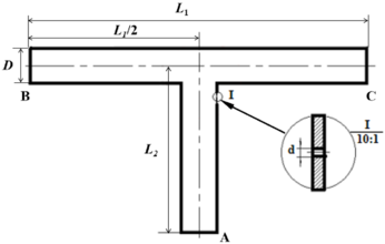
The geometric model of T-shaped tee pipe studied in this paper is shown in Figure 2, where mm; mm, mm. In the model, the continuous phase is set to natural gas, and the discrete phase is set to sand, with a density of 2650 kg/m3. The model in Figure 2 is used to analyze the erosion and wear of the pipeline by gas-solid two-phase flow.
The flow field characteristics of erosion leakage are studied by taking the flow direction of the fluid as B end inflow and A and C end outflow as examples. The analysis shows that the right side of the upper end of the branch pipe (position I in Figure 2) is a part prone to erosion and wear, and long-term wear will form perforations and cause leakage. The leakage flow field was simulated numerically based on the pipeline leakage model, and the effects of pipeline pressure, the area of the leakage orifice and the shape of the leakage orifice on the leakage rate were studied.
|
| Figure 2. Geometric model of T-type three-way pipeline |
The Multizone method in ANSYS Meshing module is used to divide the meshes at the intersection of main pipe and branch pipe and the straight pipe part. This method combines the advantages of structured and unstructured grids, that is, different grids are selected for different regions. Specifically, the geometric model is divided into blocks first and then divided, and the geometric model is automatically decomposed into mapping region and free region, and then the region is automatically judged and the pure hexahedral mesh is generated. For the regions that do not meet the conditions, a better unstructured mesh is adopted.
This paper is a study of pipe erosion by gas-solid two-phase flow, so two factors of continuous phase and discrete phase should be considered at the same time. Therefore, boundary conditions should be set according to continuous phase and discrete phase, and the interpolation mode of governing equation and the setting of solving parameters should also be considered. (1) The calculation model of continuous phase boundary condition setting is Standard RNG model, the fluid domain is natural gas, the operating pressure is the default value, the inlet type is Velocity-Inlet, the flow direction is perpendicular to the boundary, the coordinate system is absolute coordinate system, and the total temperature is 298.15 K. The exit type was Outflow, and wall boundary condition was Wall. (2) The calculation model of discrete phase boundary conditions was DPM model, the pipe wall type was reflected, the physical model was Erosion model, and the solid particles were assumed to be uniformly spherical. After the continuous phase was solved, the discrete phase was added. The type was selected as sand and its density was set to 2650 kg/m3.
4. Analysis of influencing factors
4.1 Main factors affecting erosion and wear
When the impact conditions of the tiny particles are different, the erosion and wear effect caused by the impact of the material surface is also different. The gas-solid two-phase flow moves in the pipeline. The discrete phase of the solid particles will be affected by the continuous phase gas. The velocity and flow direction of the gas will affect the movement of the solid particles. According to the kinetic energy theorem, the larger the velocity of a particle, the greater the impulse it has. Therefore, when the flow direction and velocity of the gas change, the movement of the particles will be affected, which in turn will affect the erosion and wear effect of the pipeline.
From Eq.(8) of the erosion rate, it can be concluded that the factors affecting the erosion wear efficiency are the mass flow rate and particle diameter.
In this paper, the impact of fluid velocity, particle mass flow rate and particle diameter are mainly analyzed when studying the erosion wear of three-way pipeline.
4.2 Influencing factors of the flow field characteristics at the leak hole
When the hole leaks, the pressure in the pipe can be regarded as constant pressure. It is assumed that the fluid does not exchange energy in the process of flowing in the pipe. In this ideal state, Bernoulli equation and continuity equation are used to study the model in Figure 1.
Based on Bernoulli equation and continuity equation, the analysis of Sections 1 and 3, 1 and 4 can be carried out to obtain Eqs.(11):
|
|
(11) |
where is the amount of resistance loss along the way from Section 1 to Section 3, is the amount of resistance loss along the way from Section 1 to Section 4, is the cross-sectional area at point 1, is the cross-sectional area at point 3, and is the cross-section at point 4 area.
According to Eq.(11), it can be known that the factors affecting the pipeline leakage flow field include the area of the leakage orifice, the pressure difference between inside and outside the leakage orifice (i.e., the pressure in the pipe), etc. And when the shape of the leakage hole is different, the characteristics of the pipeline leakage flow field will also change. When studying the factors that affect the leakage flow field characteristics of the small hole of the pipeline, three factors are selected under the normal temperature state: the pressure in the pipe, the area of the leakage orifice, and the geometry of the leakage orifice.
5. Simulation results and discussion
5.1 Erosion wear simulation analysis of tee pipes
5.1.1 Influence of Gas Velocity on three-way Pipeline
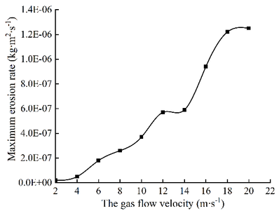
The flow direction is B-end, A-end in and C-end out, only the gas velocity is changed, and the remaining conditions are fixed, and the erosion wear of T-shaped tee is numerically simulated. Select ten groups of different flow rates, such as 2 m/s, 4 m/s, 6 m/s, 8 m/s, 10 m/s, 12 m/s, 14 m/s, 16 m/s, 18 m/s, 20 m/s, etc., and select four erosion wear cloud images at different flow rates, as shown in Figure 3. The trend that the maximum erosion wear rate varies with the air flow velocity, as shown in Figure 4.

|
| Figure 3. Cloud diagram of erosion rate of tee tube under different flow velocity |
|
| Figure 4. Curves of maximum erosion rate under different fluid velocity |
As can be seen from Figure 3, the position of erosion wear on the wall of T-shaped tee pipe is not affected by air velocity, and its position is basically the same. The maximum erosion rate occurs near the outlet of the main wall facing the branch pipe. It can be seen from Figure 4 that when other conditions remain unchanged, the velocity of medium increases and the erosion rate increases gradually, but the increase of erosion rate is nonlinear. When the velocity is between 1-14 m/s, the maximum erosion wear rate increases slowly; when the velocity is between 14-18 m/s, the maximum erosion wear rate increases greatly; when the velocity is greater than 18 m/s, the maximum erosion rate remains stable and the increase is small.
Because when the velocity is low, the flow rate is slow, and the ability of gas to carry solid particles is weak, so the erosion rate is small with the increase of gas velocity, the ability of gas to carry solid particles increases, and the impact of particles on the wall of the pipe becomes greater. This is because with the increase of gas velocity, the kinetic energy of particles also increases, and the impact energy of high-speed particles colliding with the wall also increases. However, when the flow rate reaches 18 m/s, due to the decrease of the followability of small solid particles, the impact force of particles on the pipe wall is not enhanced, so the relative increase of the erosion rate is not large.
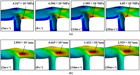
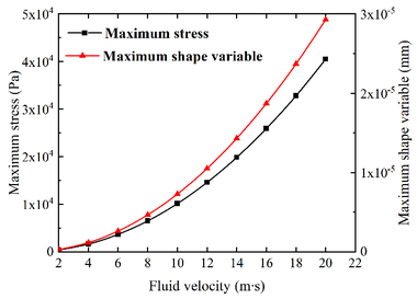
The pressure produced by the airflow at different speeds is introduced into the inner wall of the T-shaped tee, and then through the fluid-solid coupling treatment, the stress cloud diagram and deformation cloud diagram of the T-shaped tee at different air velocities are obtained. The stress nephograms and deformation nephograms of the selected flow rates of 2 m/s, 8 m/s, 14 m/s and 20 m/s are shown in Figure 5. When the velocity of the gas is changed, the stress and deformation displacement of the tee also change. Because the greater the gas velocity, the greater the kinetic energy, the impact force of the gas on the three-way pipe wall increases, and the stress and deformation of the three-way pipe in-crease significantly, and the change trend is the same and increases exponentially. The relationship between stress and deformation and gas velocity is shown in Figure 6.
|
| Figure 5. Stress and deformation nephogram under different fluid velocity. (a) Stress nephogram at different flow rates. (b) Deformation cloud images at different flow rates |
|
| Figure 6. Variation trend curve of pipeline stress and shape variables under different gas flow rates |
5.1.2 Effect of mass flow on erosion wear of three-way pipeline
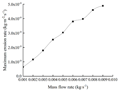
The flow direction of the fluid is B end, A end into C end out, and the mass flow is respectively 0.001 kg/s, 0.002 kg/s, 0.003 kg/s, 0.004 kg /s, 0.005 kg /s, 0.006 kg /s, 0.007 kg /s, 0.008 kg/s and 0.009 kg/s. The numerical simulation of erosion wear of T-tee pipe is carried out. Choose four erosion and wear cloud diagrams under different particle mass flow rates, as shown in Figure 7. After analysis, the curves of the maximum erosion rate changing with mass flow rate are shown in Figure 8.

|
| Figure 7. Erosion cloud diagram under different particle mass flow rates |
|
| Figure 8. Curves of maximum erosion rate under different mass flow rates |
It can be seen from Figures 7 and 8 that as the mass flow rate of particles in-creases, the maximum erosion rate continues to increase, but the erosion and wear parts on the T-shaped tee tube are basically the same. The main reason is that due to the increase of particle flow, the number of particles colliding with the pipe wall in a single time period is more than the former, and the erosion and wear rate is correspondingly in-creased.
5.1.3. Influence of particle diameter on the erosion and wear of tee
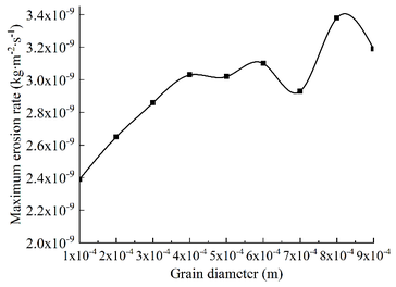
B end and A end go in and C end out, and the particle size is taken as follows: 0.0001 m, 0.0002 m, 0.0003 m, 0.0004 m, 0.0005 m, 0.0006 m, 0.0007 m, 0.0008 m and 0.0009 m. Other conditions remain unchanged, and the numerical simulation of erosion wear of T-shaped tee is carried out. Four erosion wear cloud images with different particle diameters were selected, as shown in Figure 9. In addition, the relationship curve between particle diameter and maximum erosion rate can be obtained, as shown in Figure 10.

|
| Figure 9. Erosion cloud images under different particle diameters |
|
| Figure 10. The relationship between particle diameter and maximum erosion rate |
It can be seen from Figures 9 and 10 that as the particle size increases, the erosion and wear areas and positions on the wall of the T-shaped tee tube are basically the same. The larger the particle diameter, the more obvious the erosion and abrasion effect formed on the pipe wall surface, and the greater the erosion rate, but the degree of increase gradually decreases. Because the weight of particles with larger diameters is larger than that of particles with smaller diameters. Under the same conditions, the erosion kinetic energy of the larger particle size is greater, and the impact force in the concentrated area of the offset erosion wear is stronger, so the erosion wear rate increases. However, because the mass and flow rate of the particles remain unchanged, increasing the particle diameter is equivalent to increasing the weight of the particle, and the number of particles will decrease. The number of collisions between sand particles and the wall per unit time will decrease. The mutual superposition causes the increase of the maximum erosion wear rate to gradually weaken with the increase of the particle size.
By analyzing the erosion wear of T-shaped pipe, when the flow direction of the fluid does not change, the erosion wear position of the pipe will not change when other influencing factors are changed. Therefore, with the accumulation of erosion wear will cause pipeline leakage. In order to better study the erosion leakage of pipeline, it is necessary to carry out the simulation analysis of pipeline leakage and carry out the corresponding experimental verification. During the erosion simulation and experiment of the leakage, the flow rate of the fluid is selected to enter at B end and flow out at A end and C end for re-search and analysis.
5.2 Simulation analysis of three-way pipeline leakage
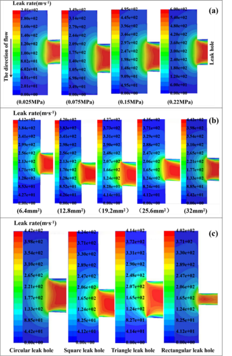
When the influence of the pressure in the pipeline on the leakage characteristics is studied, the initial pressure in the pipeline is set as 0.025 MPa, 0.075 MPa, 0.15 MPa and 0.22 MPa respectively. When studying the influence of the size of the leakage orifice area on the leakage characteristics, the circular leakage orifice is used for analysis. The area of the leakage orifice is 6.4 mm2, 12.8 mm2, 19.2 mm2, 25.6 mm2 and 32 mm2 respectively. The leakage hole is not necessarily round, so when studying the influence of the shape of the leakage hole on the leakage characteristics, under the condition that the area of the leakage hole is equal, the shapes of the leakage hole are respectively round, square, equilateral triangle, and rectangle. The cloud diagram of leakage rate under different influencing factors was obtained by simulation in Fluent, as shown in Figure 11.
| Figure 11. Cloud map of gas leakage velocity of leakage hole under different influencing factors. (a) Leakage rates at different pressures in the pipeline. (b) Leakage rate with different orifice area. (c) Leakage rate when the shape of the leakage orifice is different |
The contours of the gas leakage fluid are convex arcs. As can be seen from the color in the cloud image, leakage velocity increases gradually from the outside to the inside along the isoline, and the gas leakage rate reaches the maximum at the leakage hole. When the gas enters the leak hole, due to the impact of the fluid, the streamline curves at the corner, generating vortex movement. According to the vortex sound theory, the sound source is generated at the leakage hole, which provides a basis for the subsequent location of the pipeline leakage point.
As can be seen from Figure 11(a), with the increase of pressure, the leakage amount of pipeline hole leakage gradually increases. This is because when leakage occurs, the pressure difference will be generated at both ends of the inlet and outlet of the leak hole. As can be seen from Figure 11(b), with the increase of the area of the leakage orifice, the leakage amount of the pipeline is gradually increasing.
According to Figure 11(c), when the area of the leakage orifice is equal, the gas velocity of the circular leakage orifice is 442 m/s, the gas velocity of the square leakage orifice is 424 m/s, the gas velocity of the equilateral triangle leakage orifice is 414 m/s, and the gas velocity of the rectangular leakage orifice is 402 m/s. The reason is that rectangle has the largest wet perimeter length, square and triangle have the second, and circle has the smallest. When the gas is leaked through the leakage orifice, the greater the wet circumference length of the leakage orifice is, the greater the energy loss of the air flow will be, thus the smaller the speed will be. The wet circumference length of the rectangle is the largest, so the energy loss is greater. Therefore, the gas leakage rate of the rectangular leakage orifice is the slowest in the leakage orifice of these several shapes.
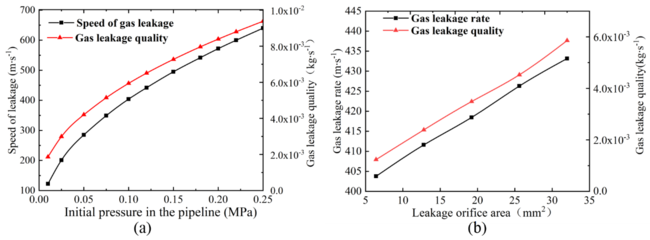
According to the simulation values, the relation diagrams of different pressures and leakage rates and quantities and the relation diagrams of different leakage hole areas and leakage rates and quantities can be obtained, as shown in Figures 12 (a) and (b). As can be seen from the graph, with the increase of the pressure and the area of the leakage hole, the leakage rate and quantity are gradually increasing. However, with the increase of the pressure and the area of the leakage hole, the slope of the curve of the leakage rate and quantity is gradually decreasing, indicating that the increase rate is gradually decreasing.
6. Experimental verification of gas leakage mass flow rate
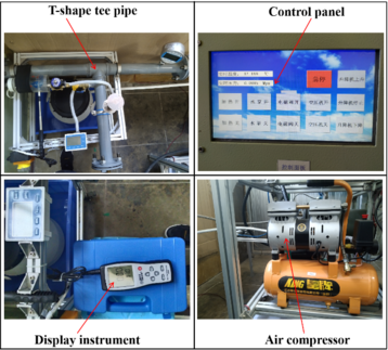
Build a T-shaped tee pipeline leakage experimental device to verify the numerical simulation, observe the gas pipeline keyhole leakage, simulate the leakage process under different pipe pressure and leakage orifice area, by comparing the experimental results with the simulation data to verify the correctness of the CFD numerical simulation results. Build a small hole leakage experiment platform (Figure 13).
|
| Figure 13. Experimental platform |
The experimental platform consists of air compressors, solenoid valves, valves, three-way pipelines, gas pipelines, control panels, wind speed measurement devices and corresponding data acquisition devices. Air is the experimental medium, and the opening and closing of the solenoid valve is used to control the valve to simulate the leakage of small holes in different areas. Adjust the input pressure value of the air compressor to simulate the effect of different pressure on the leakage of the small hole.
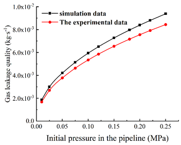
Use the control panel to precisely control each system of the device, and control and adjust the air compressor in real time according to the pressure gauge data. In the experiment, the initial pressure in the tube was taken as 0.01, 0.025, 0.05, 0.075, 0.1, 0.12, 0.15, 0.18, 0.2, 0.22, 0.25 MPa etc. When the value of the pressure gauge reaches a steady state, open the electromagnetic valve for test. The air volume measured by the measuring instrument is used to approximately represent the amount of gas leakage in the case of key-hole leakage in the pipeline. The leakage data measured in the experiment are shown in Table 1. The simulation results are compared with the laboratory data, and the comparative analysis results are shown in Figure 14.
| Pressure in the pipe/MPa | 0.025 | 0.5 | 0.075 | 0.1 | 0.15 | 0.18 | 0.22 | 0.25 |
| Leakage/kg·s-1 | 0.0030 | 0.0038 | 0.0046 | 0.0053 | 0.0065 | 0.0072 | 0.0079 | 0.0084 |
|
| Figure 14. Comparison of simulation results and experimental results |
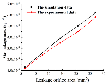
When the initial pressure is constant, the areas of the adjusted leakage orifice are 6.4, 12.8, 19.2, 25.6, 32.0 mm², etc. After the value of the pressure gauge is stable, perform the experiment. The leakage air volume values under different leakage orifice were obtained, as shown in Table 2. The simulation results are compared with the data obtained in the laboratory, and the comparative analysis results are shown in Figure 15.
|
| Figure 15. Comparison of simulation results and experimental results |
| Leakage orifice area /mm² | 6.4 | 12.8 | 19.2 | 25.6 | 32.0 |
| Gas leakage mass flow rate /kg·s-1 | 0.0012 | 0.0024 | 0.0035 | 0.0045 | 0.0058 |
The experimental and simulation results are compared and analyzed. The experimental value is always smaller than the simulation result. Although there is a certain difference between the two, the trend of the obtained value is approximately the same. As can be seen from the line chart, when the area of the leakage orifice is small and the pressure in the pipe is low, the error between the experimental value and the simulation value is relatively small and the numerical value is similar. As the area of the leakage orifice in-creases or the pressure in the pipeline increases, the error value between the simulation results and the experimental results increases and there is a big difference between the results.
The reasons are as follows: (1) The internal pressure set by CFD simulation analysis is constant pressure, which is not affected by external conditions, but during the experiment, the internal pressure is not absolute constant pressure. (2) In the CFD simulation analysis, the boundary conditions are set to ideal conditions, and the ideal state cannot be achieved in the actual test. (3) In the CFD simulation analysis, there is no energy exchange with the external environment in the process of gas leakage, but there is energy loss in the actual leakage, and the external environment and operation errors will increase the experimental error. (4) When the area of the leakage orifice is larger and the pressure in the pipe is higher, the air flow in the leak hole is more disordered, which is more different from the boundary conditions in the ideal state.
7. Conclusions
(1) Different influence factors have different degrees of erosion wear on pipelines, but the erosion wear position always appears at the intersection of the main pipe and the branch pipe of the tee pipe. And the stress - strain position of the pipeline and the serious erosion wear position basically coincide.
(2) When the airflow velocity, particle mass flow, and particle diameter increase, the maxi-mum erosion rate of the pipeline gradually increases, but with the gradual increase of various variables, the increase in the maximum erosion rate gradually decreases.
(3) When a small hole leakage occurs in a pipeline, the greater the initial pressure, the greater the pipeline leakage rate, and the larger the leakage orifice area, the greater the leakage rate. The leakage rate of different leakage void areas is also different. Under the same conditions, the leakage rate of circular, square, triangular, and rectangular leakage holes is arranged in decreasing order.
Acknowledgments
The author sincerely thanks the authors for their support for this paper. Once again, I would like to thank the scientific research project supported by the Shanxi Scholarship Council of China (2020-110) and the Special project of scientific and technological cooperation and exchange in Shanxi Province (202104041101001), the Fundamental Research Program of Shanxi Province (20210302123038) and the National Natural Science Foundation of China (52174147). Moreover, the author sincerely thanks Professor Junsheng Zhao of North University of China for his critical discussion and reading in the process of manuscript preparation.
References
[1] Martins F., Felgueiras C., Smitkova M., Caetano N. Analysis of fossil fuel energy consumption and environmental impacts in European countries. Energies, 12(6):964, 2019.
[2] Cesur R., Tekin E., Ulker A. Can natural gas save lives? Evidence from the deployment of a fuel delivery system in a developing country. Journal of Health Economics, 59:91-108, 2018.
[3] Guo Y.B., Meng X.L., Wang D.G., Meng T., Liu S.H., He R.Y. Comprehensive risk evaluation of long-distance oil and gas transportation pipelines using a fuzzy petri net model. Journal of Natural Gas Science and Engineering, 33:18-29, 2016.
[4] Akhmadeev A.G., Vinh P.T., Tam L.D. Implementation of adaptive gathering systems as the method to optimize oil transportation at offshore field (Russian). Oil Industry Journal, 2019(02):78-81, 2019.
[5] Zhou X.Y., Zhang H.R., Xin S.C., Yan Y.M., Long Y., Yuan M., Liang Y.T. Future scenario of China’s downstream oil supply chain: Low carbon-oriented optimization for the design of planned multi-product pipelines. Journal of Cleaner Production, 244:118866, 2020.
[6] Yang X.T., Qiu K.B., Zhang Y., Huang Y.J., Fan W.T., Pan Y.W., Xu G.W., Xian C.G. Analyzing unexpected sanding issues in the high-pressure/high-temperature, tight-sandstone keshen gas reservoir, western China. SPE Drilling & Completion, 33(03):192-208, 2018.
[7] Ding J.P., Cheng Y.F., Yan C.L., Song B.J., Sun H., Teng F. Experimental study of sand control in a natural gas hydrate reservoir in the South China sea. International Journal of Hydrogen Energy, 44(42):23639-23648, 2019.
[8] Qiu S.Z., Wang G.R., Wang L.Z., Fang X. A downhole hydrocyclone for the recovery of natural gas hydrates and desanding: The CFD simulation of the flow field and separation performance. Energies, 12(17):3257, 2019.
[9] Li D.G., Chen L., Miao Q., Liu G., Ren S.Y., Wang, Z.Q. Simplified layer model for solid particle clusters in product oil pipelines. Energies, 12(24):4809, 2019.
[10] Okonkwo P.C., Shakoor R.A., Zagho M.M., Mohamed A.M.A. Erosion behaviour of API X100 pipeline steel at various impact angles and particle speeds. Metals, 6(10):232, 2016.
[11] Wang C., Farhat Z., Jarjoura G., Hassan M.K., Abdullah A.M. Indentation and erosion behavior of electroless Ni-P coating on pipeline steel. Wear, 376-377:1630-1639, Part B, 2017.
[12] Coker E.H., Peursem D.V. The erosion of horizontal sand slurry pipelines resulting from inter-particle collision. Wear, 400-401:74-81, 2018.
[13] Yan H.W., Yang X., Hou X.R., Wang L., Li P.C. Research on the performance of a new external occlusion device for pressure vessel leakage. Strojniski Vestnik-Journal of Mechanical Engineering, 66(11):668-676, 2020.
[14] Yang H.N., Chen J.H., Chiu H.J., Kao T.J., Tsai H.Y., Chen J.R. Confined vapor explosion in Kaohsiung City - A detailed analysis of the tragedy in the harbor city. Journal of Loss Prevention in the Process Industries, 41:107-120, 2016.
[15] Shabarchin O., Tesfamariam S. Risk assessment of oil and gas pipelines with consideration of induced seismicity and internal corrosion. Journal of Loss Prevention in the Process Industries, 47:85-94, 2017.
[16] Badida P., Balasubramaniam Y., Jayaprakash J. Risk evaluation of oil and natural gas pipelines due to natural hazards using fuzzy fault tree analysis. Journal of Natural Gas Science and Engineering, 66:284-292, 2019.
[17] Shabarchin O., Tesfamariam S. Internal corrosion hazard assessment of oil & gas pipelines using bayesian belief network model. Journal of Loss Prevention in the Process Industries, 40:479-495, 2016.
[18] Zhang J., Yi H., Huang Z., Du J.D. Erosion mechanism and sensitivity parameter analysis of natural gas curved pipeline. Journal of Pressure Vessel Technology, 141(3):034502, 2019.
[19] Duan H.F., Pan B., Wang M.L., Chen L, Zheng F.F., Zhang Y. State-of-the-art review on the transient flow modeling and utilization for urban water supply system (UWSS) management. Journal of Water Supply: Research and Technology-Aqua, 69(8):858-893, 2020.
[20] Zeng Z., Luo R. Numerical analysis on pipeline leakage characteristics for incompressible flow. Journal of Applied Fluid Mechanics, 12(2):485-494, 2019.
[21] Deng Y.J., Hou H., Fang L.C., Yuan Q., Yu B., Liang Y.T. Numerical simulation on the dispersion of natural gas releases from a buried pipeline. Heat Transfer Engineering, 39(7-8):687-699, 2018.
[22] Zhang J.X., Kang J., Fan J.C., Gao J.C. Study on erosion wear of fracturing pipeline under the action of multiphase flow in oil & gas industry. Journal of Natural Gas Science and Engineering, 32:334-346, 2016.
[23] Zhao W.M., Wang C., Zhang T.M., Yang M., Han B., Neville A. Effects of laser surface melting on erosion–corrosion of X65 steel in liquid–solid jetimpingement conditions. Wear, 362-363:39-52, 2016.
[24] Ou G.F., Bie K., Zheng Z.J., Shu GP., Wang C., Cheng B. Numerical simulation on the erosion wear of a multiphase flow pipeline. The International Journal of Advanced Manufacturing Technology, 96:1705–1713, 2018.
[25] Wang K., Li X.F., Wang Y.S., He R.Y. Numerical investigation of the erosion behavior in elbows of petroleum pipelines. Powder Technology, 314:490-499, 2016.
[26] Kang R., Liu H.X. A mechanistic model of predicting solid particle erosion on the symmetry plane of elbows for annular flow. Journal of Energy Resources Technology, 141(3):032907, 2019.
[27] Xu J.Y., Lian Z.H., Hu J., Luo M. Prediction of the maximum erosion rate of gas–solid two-phase flow pipelines. Energies, 11(10):2773, 2018.
[28] Deng Y.J., Hou H., Fang L.C., Yuan Q., Yu B., Liang Y.T. Numerical simulation on the dispersion of natural gas releases from a buried pipeline. Heat Transfer Engineering, 39(7-8):687-699, 2018.
[29] Jiang M.R., Yu J.X., Li Z.G., Zhong W.J., Wu Z.H., Yu Y. Laboratory investigation into the oil diffusion from submarine pipeline under water flow. Acta Oceanologica Sinica, 37:96-103, 2018.
[30] Zhang Y.X., Zhu J.L., Peng Y.M., Pan J., Li Y.X. Experimental research of flow rate and diffusion behavior of nature gas leakage underwater. Journal of Loss Prevention in the Process Industries, 65:104119, 2020.
[31] Mu Z., Zhang H.G. Numerical investigation on impacts of leakage sizes and pressures of fluid conveying pipes on aerodynamic behaviors. Journal of Vibroengineering, 19:5434-5447, 2017.
[32] Ebrahimi-Moghadam A., Farzaneh-Gord M., Deymi-Dashtebayaz M. Correlations for estimating natural gas leakage from above-ground and buried urban distribution pipelines. Journal of Natural Gas Science and Engineering, 34:185-196, 2016.
[33] Zhang Y.X., Zhu J.L., Teng L., Song C.Y., Li Y.X. Experimental research of LNG accidental underwater release and combustion behavior. Journal of Loss Prevention in the Process Industries, 64:104036, 2020.
[34] Dong Y., Wang H. A simulation study of natural gas pipeline leakage and diffusion in the atmosphere. Agro Food Industry Hi Tech., 28(1):3078-3081, 2017.
[35] Guo Y.B., Liu C.C., Wang D.G., He R.Y. Numerical study and safety spacing of buried parallel gas pipelines: A study based on TNT equivalent method. International Journal of Pressure Vessels and Piping, 168:246-257, 2018.
[36] Yuan F., Zeng Y., Luo R., Khoo B.C. Numerical and experimental study on the generation and propagation of negative wave in high-pressure gas pipeline leakage. Journal of Loss Prevention in the Process Industries, 65:104129, 2020.
[37] Mocnik U., Blagojevic B., Muhic S. Numerical analysis with experimental validation of single-phase fluid flow in a dimple pattern heat exchanger channel. Strojniski Vestnik-Journal of Mechanical Engineering, 66:544-553, 2020.
[38] Vieira R.E., Parsi M., Zahedi P., McLaury B.S., Shirazi S.A. Sand erosion measurements under multiphase annular flow conditions in a horizontal-horizontal elbow. Powder Technology, 320:625-636, 2017.Document information
Published on 20/05/22
Accepted on 06/05/22
Submitted on 04/08/21
Volume 38, Issue 2, 2022
DOI: 10.23967/j.rimni.2022.05.001
Licence: CC BY-NC-SA license
Share this document
Keywords
claim authorship
Are you one of the authors of this document?
