ABSTRACT
HPR1000 is an advanced nuclear power plant (NPP) with the significant feature of an active and passive safety design philosophy, developed by the China National Nuclear Corporation. On one hand, it is an evolutionary design based on proven technology of the existing pressurized water reactor NPP; on the other hand, it incorporates advanced design features including a 177-fuel-assembly core loaded with CF3 fuel assemblies, active and passive safety systems, comprehensive severe accident prevention and mitigation measures, enhanced protection against external events, and improved emergency response capability. Extensive verification experiments and tests have been performed for critical innovative improvements on passive systems, the reactor core, and the main equipment. The design of HPR1000 fulfills the international utility requirements for advanced light water reactors and the latest nuclear safety requirements, and addresses the safety issues relevant to the Fukushima accident. Along with its outstanding safety and economy, HPR1000 provides an excellent and practicable solution for both domestic and international nuclear power markets.
Keywords
HPR1000 ; Active and passive safety ; Advanced nuclear power reactor
1. Introduction
The use of nuclear energy for electricity generation began in the late 1950s and went through several phases over the subsequent half century [ 1 ,2 ]. Today, nuclear energy contributes 11% of the worlds electricity, with over 435 power reactors in 31 countries [ 3 ,4 ]. The designs of nuclear power plants (NPPs) are categorized by “generation.” After the prototype reactors of Generation-I and the commercial reactors of Generation-II, Generation-III light water reactors (LWRs) incorporate state-of-the-art improvements in the areas of fuel technology, thermal efficiency, and safety systems [ 5 ,6 ]. The most-widely-accepted criteria for Generation-III LWRs are contained in two documents: the Advanced Light Water Reactor Utility Requirements Document (URD) [ 7 ] issued by the US Electric Power Research Institute (EPRI), and the European Utility Requirements for LWR Nuclear Power Plants (EUR) [ 8 ] issued by a cooperative organization of European utilities. URD and EUR provide comprehensive requirements for Generation-III NPPs (or advanced NPPs), including requirements for safety design, performance design, and economic competitiveness. The first batch of Generation-III NPPs, such as AP1000 and European pressurized reactor (EPR), has been deployed since the beginning of the 21st century and will shortly be connected to the grid† .
The Fukushima Daiichi NPP accident that occurred on March 11, 2011 drew worldwide attention onto the safety of NPPs. The International Atomic Energy Agency (IAEA), governments, and nuclear safety authorities all issued special reports on the lessons learned from the Fukushima accident (e.g., Refs. [ 9 , 10 , 11 and 12 ]). These reports focused on areas such as protection against external events, the robustness of emergency power and ultimate heat sinks, the safety of the spent fuel pool, the emergency responses for multiple-unit accidents, and the inhabitability and availability of emergency facilities [ 13 ]. Safety inspections, or stress tests, and necessary improvements were made for current NPPs based on the Fukushima feedback (e.g., Refs. [ 14 , 15 and 16 ]). In addition, safety requirements for new NPPs were also considered and discussed, as reflected in documents such as Safety of New NPP Designs [ 17 ] drafted by the Western European Nuclear Regulators Association (WENRA), Safety of Nuclear Power Plants: Design (No. SSR-2/1, Rev.1) [ 18 ] drafted by the IAEA, and Safety Requirements for New NPPs during 12th Five-Year Plan drafted by the China National Nuclear Safety Administration (NNSA). The improved safety requirements for new NPPs in the above documents generally cover the following aspects: a revised and strengthened defense-in-depth approach, response capability for beyond-design-basis accidents (BDBAs) including multiple failures, the practical elimination of large radioactivity release to mitigate off-site emergency, and protection against internal and external hazards. In addition, concepts such as residual risk and a plant autonomy period were brought into discussion in the international nuclear power industry.
The technology of advanced NPPs has been mainstreamed and nuclear safety standards for new NPPs in the post-Fukushima era will be stricter. With this situation as a background, the China National Nuclear Corporation (CNNC) developed the evolutionary advanced pressurized water reactor (PWR) HPR1000. The design makes full use of proven technology from the design, construction, and operation experience of the large PWR fleet in China, and introduces a number of advanced design features to meet the latest safety requirements and address the feedback from the Fukushima accident.
The CNNC has been dedicated to developing advanced PWRs for the past two decades, with an R&D program going through three phases, which are respectively represented by three successively developed models known as CNP1000, CP1000, and HPR1000. The development of CNP1000 occurred in 1999, and CP1000 has incorporated 22 major improvements based on CNP1000 since 2007. The concept of HPR1000 was proposed as the final solution for the Generation-III PWR, with a key technology research program launched in January 2010. After the Fukushima accident, the program gathered pace with the complementary research prompted by the Fukushima feedback.
In April 2013, the basic design of HPR1000 was reviewed by an expert group organized by the China Nuclear Energy Association (CNEA). The first deployment of HPR1000 is at the units 5 and 6 of Fuqing NPP, located in Fujian Province. Construction started on May 7, 2015 after the preliminary safety analysis report (PSAR) was reviewed and a construction license was granted by the NNSA.
2. Design philosophy
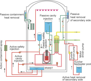
The fundamental safety functions to be ensured for nuclear power reactors are: control of the reactivity, removal of heat from the core and the spent fuel, and confinement of radioactive materials and control of operational discharges, as well as limitation of accidental releases. In order to achieve these safety functions for HPR1000, a defense-in-depth concept is performed throughout all safety-related activities to ensure that they are subject to overlapping provisions. Structures, systems, and components important to safety will be capable of withstanding identified initiating events with sufficient robustness; this is ensured by design criteria such as redundancy, diversity, and independence. Active and passive safety design is the most remarkable innovation for HPR1000 and is also a typical example of fulfilling the diversity criteria. The design does not only inherit mature and reliable active technologies, but also introduces passive systems as the backup for the active systems in case of a loss of alternate current (AC) power. Both active and passive features are employed to guarantee the safety functions of emergency core cooling, residual heat removal, in-vessel retention (IVR) of the molten core, and containment heat removal (Fig. 1 ). It is worth pointing out that the application of the passive systems does not provide an excuse for reducing the design requirements of the active systems. The availability of the active system must first be ensured, with the passive system as a backup provision.
|
|
|
Fig. 1. Active and passive systems of HPR1000. Red line−active systems; green line−passive systems; IRWST−in-containment refueling water storage tank. |
Due to the inherent safety features of NPPs, an initial deviation will cause no significant safety-related effect or bring the plant toward a safe condition. Here are a few typical instances: The reactor core is designed with negative reactivity coefficient feedbacks; the control rods are inserted into the reactor by gravity in case of a power cut-off; and natural circulation can be established in the reactor coolant system (RCS) as long as the integrity of the RCS is maintained and heat is removed by the secondary side of steam generators (SGs).
The target of practically eliminating large radioactivity release has drawn extensive discussion after the Fukushima accident. In order to control large release frequency (LRF) to below 10−7 per reactor-year, the design of HPR1000 emphasizes the integrity of the containment by adopting comprehensive severe accident prevention and mitigation measures against possible severe accident sequences identified by probabilistic methods and deterministic methods.
In order to further eliminate the residual risk, the design includes appropriate measures and adequate margins to protect the plant from beyond-design-basis external events such as earthquakes, flooding, and large commercial aircraft crashes. The emergency response capability is enhanced by providing mobile pumps and mobile diesel generators. The passive systems are able to operate for 72 h with a sufficient inventory of storage water and dedicated batteries, which significantly extends the plant autonomy period. As HPR1000 is a new model available after the Fukushima accident, its designers have learned from the accident and taken provisions to ensure the plants survival under a similar scenario.
The operational performance and economic goals of HPR1000 are in line with the requirements in URD and EUR, such as plant availability, design lifetime, and refueling cycle. Most of the plants equipment is proven and can be manufactured in China, providing more economic benefits and convenient equipment supply chains. The application of advanced features, such as leak-before-break (LBB) technology and an integrated reactor pressure vessel head structure, also reduce the cost and time required for both construction and maintenance.
The development of HPR1000 is based on self-reliant innovations, resulting in the possession of an independent intellectual property right. For example, the core is designed to load with 177 advanced fuel assemblies of CF3−a remarkable accomplishment, developed through years of CNNC research programs. The CNNC also developed innovative design software in nuclear design, thermo-hydraulic design and accident analysis, equipment and system design, and so on.
3. Technical features
Table 1 presents the general parameters of HPR1000, and this section briefly introduces its major technical features: the reactor core and fuel, RCS, engineering safety features, severe accident prevention and mitigation measures, and buildings and structures.
| Parameter | Value |
|---|---|
| Reactor thermal output | 3050 MWth |
| Power plant output, gross | ~1170 MWe |
| Power plant output, net | ~1090 MWe |
| Power plant efficiency, net | ~36% |
| Mode of operation | Baseload and load follow |
| Plant design life | 60 years |
| Plant availability target | ≥90% |
| Refueling cycle | 18 months |
| Safety shutdown earthquake (SSE) | 0.3 g (g, gravitation constant) |
| Core damage frequency (CDF) | <10−6 per reactor-year |
| Large release frequency (LRF) | <10−7 per reactor-year |
| Occupational radiation exposure | <0.6 person-Sv per reactor-year |
| Operator non-intervention period | 0.5 h |
| Plant autonomy period | 72 h |
3.1. Reactor core and fuel
The HPR1000 reactor core generates 3050 MWth of thermal power with an average linear power density of 173.8 W·cm−1 . The reactor core is loaded with 177 fuel assemblies, ensuring sufficient thermal margin while increasing output power. The core design permits a refueling cycle of 18 months by low-leakage loading patterns, with the flexibility of extending the refueling cycle. The CF3 fuel assembly is composed of 264 fuel rods arranged within a 17 × 17 supporting structure. The fuel rods contain UO2 pellets or Gd2 O3 -UO2 pellets. Combined with an innovative advanced zircaloy cladding material and the designs of the grid, nozzle, and guide tube, CF3 has an excellent performance and is applicable for a long refueling cycle.
Three independent means exist for core reactivity and power distribution control: burnable absorber of gadolinium (Gd2 O3 ) poisons, rod cluster control assemblies (RCCAs), and soluble boron absorber. The RCCA is comprised of 24 control rods fastened to a spider connector. The absorber material used in the control rod is Ag-In-Cd alloy or stainless steel. HPR1000 is designed with a thermal margin greater than 15% to improve safety and operational performance.
3.2. Reactor coolant system (RCS)
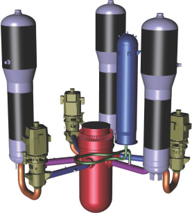
The RCS of HPR1000 is a mature three-loop design, which has gathered abundant operating experience around the world. Three loops connect in parallel to the reactor pressure vessel (RPV), each containing an SG and a reactor coolant pump (Fig. 2 ). An electrically heated pressurizer is connected to one of the reactor coolant loops. The sizes of the RPV, SGs, and pressurizer have been increased in order to accommodate larger power and provide greater tolerance for transients, reducing the potential of an unplanned reactor trip. The increased volumes of the SG secondary side also contribute to the grace time to mitigate steam generator tube rupture (SGTR) accident prior to flooding the secondary sides of the SG, and extend the time to dryout for the accident of total loss of feedwater.
|
|
|
Fig. 2. The reactor coolant system (RCS) of three loops. |
The design lifetime of the RPV is extended to 60 years by controlling the content of noxious elements in the material, reducing the initial reference temperature for nil ductility transition (RTNDT) of both the base metal and the welding material, eliminating the weld in the core shell, and providing a large water gap. The RPV is made of low-alloy steel, with the internal surface covered by stainless steel cladding for corrosion resistance. The major parts of the RPV are machined from single-piece forgings to reduce the number of welds. The use of advanced in-core instrumentation cancels the penetration through the lower head of the RPV.
The ZH-65 type SG is used for HPR1000, which is a vertical, inverted U-tube SG with natural circulation in the secondary side and an integral moisture separation device. The tubes are made of Inconel 690 alloy with excellent corrosion resistance, and supported by tube support plate (TSP), in which the holes are arranged in trefoil geometry. The parts in contact with the reactor coolant are either made of corrosion resistant alloys, or are clad with austenitic stainless steel or Inconel alloy.
The pressurizer has a total free volume of 51 m3 , to limit pressure variations during load transients and maintain RCS pressure within design limits. Overpressure protection is provided by three series of pilot-operated safety valves. Dedicated valves are designed for depressurizing the RCS upon the occurrence of severe accident. The RCS inventory is discharged through the valves to the relief tank.
The reactor coolant pump in each loop is a vertical, single-stage, shaft-sealed centrifugal pump, driven by an air-cooled, three-phase induction motor. The pump is installed with a standstill seal that is capable of maintaining leak-tightness of the pump shaft without requiring an active seal water injection system in case of pump trip.
The reactor coolant piping is integrally forged and designed according to the LBB concept. It eliminates the need to design the RCS components, piping, and supports used to accommodate the dynamic effects of large or double-ended ruptures.
3.3. Engineering safety features
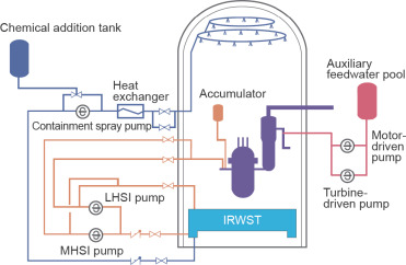
The engineering safety features are adopted to mitigate design-basis accidents (DBAs), and include a safety injection system, auxiliary feedwater system, and containment spray system (Fig. 3 ). The engineering safety features are comprised of redundant trains to fulfill single failure criteria. Independence is ensured by arranging each train in a physically separate building and supplying power by each of the emergency diesel generators.
|
|
|
Fig. 3. Engineering safety features. MHSI−middle head safety injection; LHSI−low head safety injection. |
The safety injection system consists of two active subsystems−the middle head safety injection (MHSI) subsystem and low head safety injection (LHSI) subsystem−and one passive subsystem−the accumulator injection subsystem. An in-containment refueling water storage tank (IRWST) is adopted as the water source of the injections, which provides protection against external events and makes it unnecessary to switch water sources during long-term injection phase, as compared with other NPP designs placing the refueling water tank outside the containment. The MHSI and LHSI pumps suck water from the IRWST after a loss-of-coolant accident (LOCA), and inject the borated water to the RCS for emergency core cooling in order to prevent core damage. The improvements in the configurations compared to existing NPPs include: ① The safety injection pumps are not shared with other systems in order to improve the equipment reliability and independence; ② the injection head is lowered to reduce the risk of SGTR, and ③ the boron injection tank and boron recirculation loop are cancelled to achieve system simplification.
The auxiliary feedwater system supplies emergency feedwater to the secondary side of the SG to remove core decay heat in the case of a loss of normal feedwater. The feedwater is provided from two auxiliary feedwater pools with 2 × 50% motor-driven pumps (motors can be driven by the emergency diesel generators) and with 2 × 50% turbine-driven pumps (turbines are driven by steam produced in the SGs). The diversity of the pumps improves the robustness of the system.
The containment spray system is used to maintain the integrity of the containment by limiting containment pressure and temperature within the design limits, by spraying and cooling the steam released into the containment during LOCAs or main steam line break (MSLB) accidents. The spray water is taken from the IRWST by a containment spray pump, with chemical additive to reduce airborne fission products (especially iodine) and limit the corrosion of structural material. The LHSI pump can be used as a backup for the containment spray pump to ensure the reliability of long-term spray.
3.4. Severe accident prevention and mitigation measures
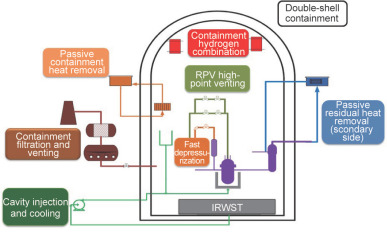
Comprehensive prevention and mitigation measures have been incorporated in the HPR1000 design against possible threats of severe accidents (Fig. 4 ), including high-pressure molten corium ejection, hydrogen detonation, basement melt-through, and long-term containment overpressure. The design also takes into account appropriate measures for specific BDBAs that are considered to be weak points of existing NPPs, such as station blackout (SBO).
|
|
|
Fig. 4. Beyond-design-basis accident (BDBA)/severe accident prevention and mitigation measures. |
The fast depressurization system of the RCS is used to depressurize the RCS rapidly during severe accidents in order to prevent the high-pressure molten corium ejection, which would cause direct containment heating. The system consists of two redundant parallel discharge lines connected to a nozzle on the pressurizer dome. Each line is installed with a gate valve and a globe valve in series.
The RPV high-point venting system is designed to remove non-condensable gases from the RPV head during accident conditions, so as to avoid adverse impact to the heat transfer of the reactor core caused by the non-condensable gases.
The cavity injection and cooling system (CIS) is used to cool the external surface of the RPV lower head by injecting water into the space between the RPV wall and the insulation layer, so as to maintain its integrity and realize the IVR of melt core debris. The CIS consists of an active subsystem and a passive subsystem. The active subsystem includes two parallel injection lines, each taking up water from the IRWST through a pump or from the fire water as a backup supply. The passive subsystem depends on a high-point tank located in the containment. In the case of a severe accident and the failure of the active subsystem, the isolation valves can be opened and the water in the tank will flow down under gravity to cool the lower head of the RPV.
The passive residual heat removal system of secondary side (PRS) is put into action in the event of an SBO and the failure of the turbine-driven auxiliary feedwater pumps, in order to provide feedwater to the secondary side of the SG in a passive way. The PRS consists of three trains connected to the three SGs, respectively. Natural circulation will be established in the closed loop between the secondary side of an SG and the heat exchanger submerged in the heat exchange tank on the upper part of the outer containment. The tank inventory can sustain the operation of the PRS for 72 h.
The containment hydrogen combination system is intended to decrease hydrogen concentration within the containment atmosphere to safe limits, in order to prevent hydrogen inflammation during DBAs or hydrogen detonation during severe accidents. The system is comprised of 33 passive autocatalytic recombiners installed inside the containment, which will be triggered automatically when the hydrogen concentration reaches the threshold.
The passive containment heat removal system (PCS) is designed to remove the heat in the containment, in order to ensure that the containment pressure and temperature will not exceed the design limits during BDBAs. The heat of the high-temperature mixture of steam and gas inside the containment will be removed by water (or water-steam) flowing in the tubes of heat exchangers installed at a high position on the internal surface of the containment, to the heat exchange tank outside the containment. The temperature difference between the atmosphere of the containment and the water in the heat exchange tank, and the elevation difference between the tank and the heat exchangers, are the driving forces enabling natural circulation to remove the containment heat. The water in heat exchange tank is heated and evaporated after the saturated temperature is reached, and the heat finally dissipates to the environment. The tank inventory fulfils the requirement of a 72-hour passive heat removal from the containment after severe accidents.
The containment filtration and venting system is an option to prevent the pressure of the containment from exceeding its bearing capability by proactive and planned venting. The filtration equipment in the venting line is used to reduce the release of radioactivity to environment as much as possible.
To prevent the events of anticipated transient without scram (ATWS), the emergency boron injection system is designed to provide rapid boration to the RCS to bring the reactor core to sub-critical state. If the normal boration system is not available, the emergency boron injection system is actuated manually to inject sufficient borated water to the RCS.
As mentioned earlier, the introduction of the passive systems is not an excuse to reduce the availability requirement for the active systems. HPR1000 still provides diverse and reliable power sources to ensure the safety of the plant under most circumstances. Under normal conditions, two independent off-site electric power supplies are used as the main power and the auxiliary power, respectively. In the case of a failure of off-site power, two diesel generators (equipped for each reactor) and one additional diesel generator (equipped for all the reactors within a plant) will be put into action as on-site emergency power. During SBO accidents, two SBO diesel generators can be relied on to bring the plant into a safe shutdown state. Even when all of the above power sources are lost, mobile diesel generators can be used for temporary power. In addition to the AC power supplies, HPR1000 has battery banks of different voltages to supply direct current (DC) power, including two independent 72-hour battery banks dedicated to the valves, instrumentation, and control load related to passive systems.
3.5. Buildings and structures
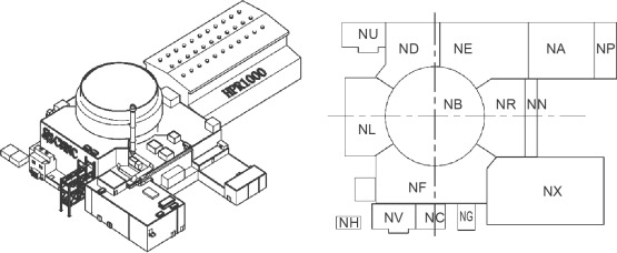
The general arrangement of HPR1000 is based on the single-unit layout, which can be divided into a nuclear island (NI), a conventional island (CI) and the balance of plant (BOP). The reactor building is located in the center of the NI, surrounded by the fuel building, the electrical building and two safeguard buildings. Other buildings are located on the periphery, such as the nuclear auxiliary building, access building, and so forth (Fig. 5 ).
|
|
|
Fig. 5. Nuclear island (NI) general layout. NB−reactor building; NF−fuel building; ND/NE−electrical building; NL−safeguard building A; NR−safeguard building B; NX−nuclear auxiliary building; NN−connection building; NU−emergency diesel generator building A; NV−emergency diesel generator building B; NA−access building; NC−emergency compressor house; NG−reactor building gantry; NP−fire protection pump station for NI; NH−SBO diesel generator building. |
Each of the redundant trains of engineering safety features is arranged in a different safeguard building, and the two safeguard buildings are placed on opposite sides of the reactor building to achieve complete physical separation. This setup minimizes the potential of common cause failures that are induced by external events. The two emergency diesel generator buildings are also physically separated, for the same reason.
The NI buildings are designed with a seismic input of peak ground acceleration of 0.3g (g, gravitation constant) for both horizontal and vertical directions. Seismic capacity is improved by an integral foundation raft built to support the reactor building, fuel building, electrical building, and safeguard buildings. A seismic margin assessment is also carried out to evaluate the plants resistance to a beyond-design-basis earthquake.
Protection against a large commercial aircraft crash is achieved by concrete shielding shells for the reactor building, fuel building, and electrical building, and by complete physical separation for the safeguard buildings. The structures, systems, and components that are important to safety are arranged so as to decrease the consequences of fires and explosions caused by external and internal events. All external natural events including earthquake, flooding, wind, tornado, tsunami, and site-related external human-caused events have been considered in the NI design. The possibilities of internal hazards such as internal flooding, missiles, pipe whipping, jetting, or fluid release have also been studied, and necessary provisions are incorporated in the NI design.
The plant arrangement separates the radioactive and non-radioactive equipment and provides separate pathways to these areas for personnel access. Moreover, this arrangement improves the convenience and efficiency of inspection, maintenance, and component replacement, with the purpose of minimizing radiation exposure.
The HPR1000 reactor containment is a double-wall structure located on a common raft. The inner containment is a pre-stressed reinforced concrete structure (including a cylindrical wall and a hemisphere dome) with a leak-tight steel liner, which is designed to withstand accident conditions (e.g., LOCAs) inside the containment and retain radioactive fission products. A sufficient margin is provided due to the large free volume (~87 000 m3 ) of the inner containment. For the leak-tightness requirement for the inner containment, the leak rate is less than 0.3% of the gas contained in the free volume per 24 h under DBAs. The outer containment is a reinforced concrete structure (including a cylindrical wall and a shallow spherical dome) that is designed to withstand external events, such as aircraft crashes, external explosions, and missiles, in order to protect the inner containment and the internal structures and equipment. The outer containment also serves as part of the water tank structure for passive cooling systems. The three heat exchange tanks are located at the same elevation on the outside surface and form a ring structure that is supported by the outer containment. The annular space between the two containment walls is maintained with a slightly negative pressure by a ventilation system, in order to collect possible leakage from the inner containment and filter it before discharging it to environment.
4. Experimental verification
As an evolutionary design of advanced PWR, HPR1000 is based on the proven technologies. The new advanced features have been successfully evaluated and verified by experiments to ensure that they enhance safety and operational performance. The experimental activities carried out over several years by the CNNC include the following critical tests related to the elaborations of passive systems, reactor core and main equipment: CIS verification test, PRS verification test, PCS verification test, reactor hydraulic integral test, reactor bypass flow tests, control rod driven line (CRDL) seismic test, reactor lower plenum mixing test, flow-induced vibration tests, and SG design verification tests.
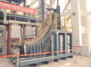
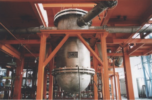
In the CIS verification test, the critical heat flux (CHF) of boiling on the RPV external surface for both the active and passive flow subsystems was measured to demonstrate the cooling capability of the CIS. The test section was half a slice of the hemispheric lower head of the RPV with an appropriate scaling ratio (Fig. 6 ). Twelve heater blocks were installed that each covered a 7.5° angular area. During the experiment, the heating power was increased gradually until boiling crisis occurred. The temperatures of the external surface of the test section were monitored continuously by thermocouples, and the boiling crisis was recognized by a sudden rise of the thermocouple signal. The test provided the bounding heat removal capacity (i.e., CHF) as a function of angular position, for both active and passive flow subsystems. The external cooling capability characterized by the CHF was therefore obtained and the effectiveness of the CIS for IVR was proved.
|
|
|
Fig. 6. Cavity injection and cooling system (CIS) test facility. |
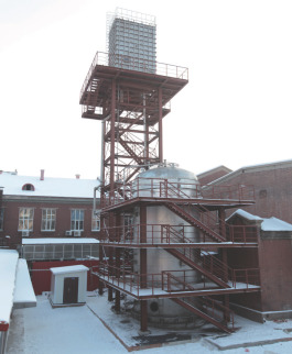
The PRS validation test was carried out to validate the heat removal capacity and design parameters of the PRS, and to test the natural circulation stability and the long-term (72 h) operating capability. The PRS test facility, called ESPRIT (Fig. 7 ), had full pressure and height, and the 1/62.5 volume of the prototype. The circulation loop of ESPRIT was comprised of a steam-water circulation loop (including a simulated SG, heat exchanger, and make-up tank), a cooling pool outside the containment and the heat removal system, a steam discharging system, and other auxiliary systems. The water in the cooling pool was heated by the heat exchanger, resulting in natural circulation in the pool, and finally, heat was dissipated to the environment by evaporation. The stable operational capability of the PRS was tested under conditions of different pressure and power. Moreover, the transient performance of the PRS was studied in an SBO accident scenario. The test proved the capability of the PRS to remove the decay heat after an SBO accident for 72 h, regardless of the availability of the turbine-driven auxiliary feedwater pump.
|
|
|
Fig. 7. Passive residual heat removal system of secondary side (PRS) test facility. |
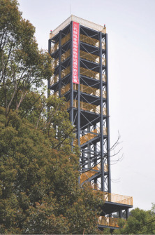
In order to support the PCS design and verify the performance of the system and of key equipment, extensive experimental studies were performed on a single-tube test facility and a comprehensive performance test facility, respectively. In the single-tube test, heat transfer mechanism in a single tube was investigated in order to provide an accurate and reliable basis for the design of the heat exchanger. The comprehensive performance test was accomplished on the full-pressure and full-height facility (Fig. 8 ) to verify the heat removal capability and operational performance of the PCS under different accidental conditions, containment atmospheres, and water levels in the heat exchange tank. The performance of key equipment was also tested. Conclusions drawn from the test included: ① The heat removal capability of the PCS can be ensured, regardless of stages (early or long term) of an accident; ② the heat removal power of the PCS decreases from start-up to normal operations, and the pressure and temperature fluctuations are too small to threaten system safety; and ③ the performance of the developed internal heat exchanger, separator, and steam discharge device meet the design requirements.
|
|
|
Fig. 8. Passive containment heat removal system (PCS) comprehensive performance test facility. |
The objective of the reactor hydraulic integral test was to obtain the flow distribution at the inlet of the reactor core and the resistance factor of the reactor parts, in order to validate the reactor thermal-hydraulic design. The diameter of the test facility was scaled to be one fourth of the prototypic value (Fig. 9 ), and the simulant fuel assembly had the same hydraulic characteristics and axial and radial flow resistance as the prototype. The test demonstrated the following: ① The flow distribution in the core is fairly uniform, with the normalized flow distribution factors in the range of 0.95 to 1.07; ② the flow in the central area is larger than in the outer area, which is consistent with the core power distribution of the low-leakage fuel management strategy, and benefits the heat removal of the fuel assemblies; and ③ the pressure drops measured for the reactor parts provide insights for the design of the reactor and of the reactor coolant pumps.
|
|
|
Fig. 9. Reactor hydraulic integral test facility. |
The reactor bypass flow tests includes the testing for the control rod guide tube bypass flow, the RPV upper head bypass flow, the bypass flow between the core baffle and barrel, and the outlet nozzle leakage flow test, with the purpose of studying the relations between bypass flows and the geometry, arrangement, or hydraulic characteristics of different internals of the RPV. The test models were designed for each of the above tests with a rational scale ratio to the prototype. The tests showed that the total bypass flow fraction measured is less than the design limit of 6.5%, which is used for the reactor thermal-hydraulic design.
The CRDL is the channel for lifting, inserting, and dropping of the RCCA, and its seismic capability is important to reactor safety. The test facility included the CRDL, a multiple point shock device, and the supporting bracket. In the seismic test, the CRDL performance, falling rod function, and structure integrity during and after an earthquake were investigated. The test proved that the CRDL meets the design requirement of resisting an input seismic load of 0.3g.
The reactor lower plenum mixing test was performed to obtain the lower plenum mixing factors under various conditions, which are used to determine the ratio of the boron water to the cold water injected during accidents. The test facility consisted of a reactor model, three-loop system, and measurement system. The reactor model was the same as that used in the reactor hydraulic integral test. Two of the loops can be injected with potassium chloride (KCl) solution. The test provided the average mixing factor of the lower plenum and the average value of the maximum mixing factors in the 120° area for each of the loops injected with KCl solution.
The flow-induced vibration tests were intended to obtain the natural vibration characteristics and flow-induced vibration response of the reactor vessel internals (RVIs), in order to verify the structural design of the RVI. The tests included a natural vibration characteristics test in air and still water, and a flow-induced vibration response test. The test model, with a scale ratio of 1:5, was adopted based on the fluid-structure interaction similarity principle, and the test conditions covered almost all predictable conditions. The test showed that flow-induced vibration of the RVI is small, stable, and random. As the stress caused by flow-induced vibration is much lower than the fatigue stress limit, it is expected that high-cycle fatigue damage will not occur during the lifetime. In the durability test where the RVI were subject to a continuous 50-hour operation with the rated flow, no loosing or falling-off was discovered in the parts and their connections. The function of the hold down spring remained, and no abrasions or scratches appeared on the core barrel flange.
The SG design verification tests can be divided into the TSP hydraulic test, the moisture separation device test, and the flow-induced vibration test of the SG heat transfer tube bundle. The purpose of the TSP hydraulic test was to verify the TSP hydraulic characteristics by measuring the pressure drop when fluid flowed through the TSP at different steam pressures, temperatures, and mass flow rates. The moisture separation device of the ZH-65 type SG consists of a primary separator and a secondary dryer. The test investigated the draining capacity of the dryer, and the flow resistance and water-steam separation capacity of the separator and the dryer under hot conditions. Moreover, the dynamic characteristics of the tube under impact were measured, and the flow-induced vibration response of the tube bundle of the SG was tested with a simulated flow under full power operating conditions.
5. Conclusions
As a Generation-III PWR design developed by the CNNC, HPR1000 fulfills the international utility requirements for advanced LWRs, and the increasingly stringent nuclear regulations and safety standards. It has also taken into account the feedback from the Fukushima accident. A number of advanced design features have been incorporated into the design, including a 177-fuel-assembly core loaded with CF3 fuel assemblies, an active and passive safety design philosophy, comprehensive severe accident prevention and mitigation measures, enhanced protection against external events, and improved emergency response capability. Large-scale test facilities were conceived, on which tests were performed to demonstrate that the new design features are capable of achieving design targets and functions, without any adverse impact on plant safety. The safety issues which have drawn extensive attentions and discussions after the Fukushima accident, such as practically eliminating the large radioactivity release, reducing the residual risk, and extending the plant autonomy period, have also been addressed with appropriate improvements.
Compared to most existing PWR NPPs in China, the HPR1000 plant has achieved a vast improvement or even a breakthrough in safety goals, with the two important probabilistic safety indicators CDF and LRF reduced by almost two orders of magnitude. HPR1000 satisfies the safety criteria for new NPPs set by the Chinese government after the Fukushima accident. In comparison with other Generation-III NPPs around the world, HPR1000 generally provides equivalent safety and performance; however, it includes additional substantial innovations in the diversity of safety features, which significantly improve the robustness of necessary safety functions under all circumstances. In addition, the economic competitiveness, constructability, operability, and maintainability of HPR1000 can be ensured because it comprehensively utilizes both proven technology and equipment, and the mature equipment supply chain in China.
Its excellent safety and performance design, and its economic competitiveness, make HPR1000 a perfect choice for new NPPs in both domestic and international markets. Notably, after the design were reviewed and approved by the respective nuclear safety authorities, the domestic and international demonstration projects of HPR1000 started construction in May and August of 2015, respectively. The future deployments of HPR1000 will not only contribute to the Chinese mid- and long-term nuclear power development plans, but also meet the clean energy needs of the international market.
Compliance with ethics guidelines
Ji Xing, Daiyong Song, and Yuxiang Wu declare that they have no conflict of interest or financial conflicts to disclose.
Nomenclature
AC- alternate current
ATWS- anticipated transient without scram
BDBA- beyond-design-basis accident
BOP- balance of plant
CDF- core damage frequency
CHF- critical heat flux
CI- conventional island
CIS- cavity injection and cooling system
CNEA- China Nuclear Energy Association
CNNC- China National Nuclear Corporation
CRDL- control rod driven line
DBA- design-basis accident
DC- direct current
EPRI- Electric Power Research Institute
EUR- European Utility Requirements for LWR Nuclear Power Plants
IAEA- International Atomic Energy Agency
IRWST- in-containment refueling water storage tank
IVR- in-vessel retention
LBB- leak-before-break
LHSI- low head safety injection
LOCA- loss-of-coolant accident
LRF- large release frequency
LWR- light water reactor
MHSI- middle head safety injection
MSLB- main steam line break
NI- nuclear island
NNSA- National Nuclear Safety Administration
NPP- nuclear power plant
PCS- passive containment heat removal system
PRS- passive residual heat removal system of secondary side
PSAR- preliminary safety analysis report
PWR- pressurized water reactor
RCCA- rod cluster control assembly
RCS- reactor coolant system
RPV- reactor pressure vessel
RVI- reactor vessel internal
SBO- station blackout
SG- steam generator
SGTR- steam generator tube rupture
SSE- safety shutdown earthquake
TSP- tube support plate
URD- Advanced Light Water Reactor Utility Requirement Document
WENRA- Western European Nuclear Regulators Association
References
- 1 International Atomic Energy Agency [Internet]. Vienna: 50 years of nuclear energy. [cited 2015 Aug 13]; Available from: https://www.iaea.org/About/Policy/GC/GC48/Documents/gc48inf-4_ftn3.pdf
- 2 OECD Nuclear Energy Agency; Nuclear energy today (2nd ed.), Nuclear Energy Agency of the OECD, Paris (2013)
- 3 World Nuclear Association [Internet]. London: nuclear power in the world today. 2016 Jan [cited 2015 Aug 13]; Available from: http://www.world-nuclear.org/info/Current-and-Future-Generation/Nuclear-Power-in-the-World-Today/
- 4 International Atomic Energy Agency; Nuclear power reactors in the world (2015 edition), IAEA, Vienna (2015)
- 5 SM Goldberg, R Rosner; Nuclear reactors: generation to generation, American Academy of Arts and Sciences, Cambridge (2011)
- 6 RP Zhang, X Zhang, LQ Zhang; Technical evolution of leading nuclear power reactor types in the world; China Nucl Power, 2 (1) (2009), pp. 85–89 2(2):184–9; 2(3):276–81; 2(4):371–9. Chinese.
- 7 Electric Power Research Institute; Advanced light water reactor utility requirement document, EPRI, Palo Alto, CA (1990)
- 8 EUR organization. European utility requirements for LWR nuclear power plants. 2001.
- 9 International Atomic Energy Agency; IAEA international fact finding expert mission of the Fukushima Dai-ichi NPP accident following the Great East Japan Earthquake and Tsunami, IAEA, Vienna (2011)
- 10 Nuclear Emergency Response Headquarters, Government of Japan. Report of Japanese government to IAEA ministerial conference on nuclear safety–the accident at TEPCOs Fukushima nuclear power stations. 2011.
- 11 C Miller, A Cubbage, D Dorman, J Grobe, G Holahan, N Sanfilippo, US Nuclear Regulatory Commission; Recommendations for enhancing reactor safety in the 21st century: the near-term task force review of insights form the Fukushima Dai-ichi accident, Progressive Management, New York (2011)
- 12 HM Chief Inspector of Nuclear Installations. Japanese earthquake and tsunami: implications for the UK Nuclear Industry. 2011.
- 13 YX Wu, DY Song, GH Zhao; Post-Fukushima tendency of nuclear power codes and standards; Nucl Sci Eng, 33 (3) (2013), pp. 329–336 Chinese.
- 14 Autorité de Sûreté nucléaire. Complementary safety assessment of the French nuclear power plants (European “stress tests”) –report by the French Nuclear Safety Authority. 2011.
- 15 European Commission. Communication from the commission to the council and the European parliament–on the interim report on the comprehensive risk and safety assessments (“stress tests”) of nuclear power plants in the European Union. 2011.
- 16 China National Nuclear Safety Administration. General technical requirements for post-Fukushima improvement actions of NPP (tentative). 2012. Chinese.
- 17 WENRA Reactor Harmonization Working Group. Report–safety of new NPP designs. 2013.
- 18 International Atomic Energy Agency; Safety of nuclear power plants: design. IAEA Safety Standards Series No.: SSR-2/1 (Rev. 1), IAEA, Vienna (2016) Forthcoming
Notes
†. The concept of Generation-III+ NPPs was also mentioned in some cases (e.g., Ref. [ 5 ]); however, these will not be differentiated from Generation-III in this article because this terms definition is thought to be ambiguous.
Document information
Published on 06/04/17
Licence: Other
Share this document
claim authorship
Are you one of the authors of this document?
