Abstract
High-frequency vibration can result in failure of the working blades. So suppressing vibration failure of blades becomes more and more important. Damping performance of viscoelastic block on blades is researched based on principle of finite element method, contact theory of elastic body and the solving equations of natural frequency. Modal and harmonic response is analyzed to obtain natural frequency, vibration displacement and stress distribution, in which different finite element models of blade are established. Effects of different adding position and thickness of viscoelastic block on damping performance are analyzed. Elastic modulus and loss factor of viscoelastic material is also changed to study their influence on damping performance. The results show that viscoelastic block applied to blades has excellent performance in reducing blade vibration. When viscoelastic block is added to mortise side, the damping performance of blade is the best. In addition, thickness of viscoelastic block and parameters of viscoelastic material have a significant effect on vibration reduction of blade.
Key words: Viscoelastic damping material, blades, vibration reduction, modal analysis, harmonic response
1. Introduction
Blades of aircraft compressor work at high temperature and high pressure, which bear centrifugal and aerodynamic force as well as corrosion, oxidation, etc. Because the working environment is very harsh, so failure of compressor blades occurs from time to time [1]. Especially, damage of the working blades due to high-speed vibration has been one type of major failure for aircraft engine [2]. In the past decades, available studies have shown that viscoelastic damping material (VDM) have an excellent effect on reducing vibration and noise. Due to its favorable properties, VDM is widely utilized in mechanical structures of navigation, vehicle transport and aerospace industries, etc. [3]. It is not only low in weight and cost, highly reliable and easily implemented, but also has a considerable ability to control vibration and noise when it is applied to lightweight and flexible structures [4]. Here, the damping performance of VDM applied to the blades is studied according to actual engineering requirements of blades.
Mechanical properties of viscoelastic material can be adjusted so as to have the required elastic modulus and loss factor at a specific temperature and frequency range. Viscoelastic damping structures mainly include free layer damping (FLD) and the constrained layer damping (CLD) [5]. Both of these structures are used to achieve a large amount of dissipative vibration energy by restraining shear deformation of viscoelastic layer, which can suppress vibration and noise effectively [6]. For viscoelastic damping material, many scholars have conducted in-depth research. Fan [7] researched the viscoelastic damping material used to reduce noise and vibration in the train, in which the damping effects of three types of damping material are studied.Yang [8]used ABAQUS software to estimate the damping property of hybrid sandwich panels. A set of modal tests were carried out to investigate vibration and damping characteristics of the hybrid sandwich panels with or without viscoelastic layers. Robinson and Kosmatka [9] studied the embedding viscoelastic damping materials in composite structures by low-cost Vacuum Assisted Resin Transfer Molding (VARTM). They confirmed that damping and stiffness is very sensitive to perforation spacing and size. However, they did not discuss parameters effect on damping performance. Zhou [10] summarized the research methods and theoretical calculation models to study static and dynamic vibration characteristics of the VDM formed structures. In addition, flexural vibration characteristic of a periodical stiffened-thin-plate filled with VDM were also researched based on a simplified-super-element-method (SSEM). Martinez and Elejabarrieta [11] presented a new inverse method to study dynamic characterization of high damping and strong frequency-dependent viscoelastic materials combing with vibration test data measured by vibration tests with resonance. Trindade [12] proposed a geometrical optimization method for passive damping treatment and applied to composite beams. Finite element models of sandwich and multilayer beams were also built. Wang and Chen [13] analyzed the damping and vibrational properties of symmetrical and asymmetric viscoelastic composite structures. Montemurro et al [14] proposed a two-level procedure of hybrid elastomer structures to maximize the loss factor of the structure. But factors affecting the damping and vibration properties were not discussed further.
At the same time, many scholars have simulated and analyzed vibration reduction performance of viscoelastic damping materials. Tan and Yu [15] proposed a finite element model of viscoelastic fine stick combined with dynamic testing methods. Zhou and Liu [16] proposed a dynamic modeling scheme of vibration damping element with VDM based on equivalent algorithm of non-viscous damping and polycondensation technique of structural dynamics model. However, parameters of VDM that effect the damping performance are not researched. Nowadays, viscoelastic materials have been applied to blades root for suppressing vibration. However,the corresponding research is not enough. Effects of different adding position and thicknesses as well as material parameters on damping properties of VDM need to be researched further.
2. Constitutive relationship of viscoelastic material
2.1 Prony series form
Properties of viscoelastic material are affected by frequency and temperature, which cannot use normal quasi-static creep and relaxation modulus to describe. Classical Hooke law also cannot be applied to viscoelastic material. New constitutive relations need to be sought. Scholars have put forward many constitutive models of viscoelastic material. Integral and derivative constitutive relations are widely used currently [17].According to the study of viscoelastic constitutive relationship [18], stress function and constitutive relation of isotropic viscoelastic materials can be written as following integral form under theory of small deformation
|
|
(1) |
where is Cauchy stress, is shear relaxation modulus, is bulk relaxation modulus, is strain partial fraction of shear deformation, is strain volume fraction of volume deformation. , and are current time, past time and element tensor respectively, in which unit of time and is second . In order to describe parameter representation of viscoelastic integral modulus functions and , Prony series form is used here.
Basic form of viscoelastic properties can be expressed by Prony series as [19]
|
|
(2) |
|
|
(3) |
where is shear modulus, is final shear modulus, is bulk modulus, is final bulk modulus. and are relaxation time of Prony series component. The relative modulus is defined as
|
|
(4) |
|
|
(5) |
where and are transient moduli of viscoelastic material. Their definitions are expressed as following
|
|
(6) |
|
|
(7) |
For viscoelastic problem, Poisson ratio of viscoelastic body is usually a function of time. But sometimes it can be approximated as a constant, which is based on the elastic constant relation. So G(t) and K(t) can be expressed as
|
|
(8) |
where is relaxation modulus determined by experimental data. The corresponding coefficients of are the same and Poisson's ratio is constant. In ANSYS software, orders of Prony series and may not be same. Relaxation time and are also not same. So in and , , , . Similar to and , transient relaxation modulus is defined as
|
|
(9) |
Combined with equation (8), and can be expressed as
|
|
(10) |
2.2 Parameters of viscoelastic damping material
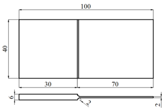
Material of blade plate is plain carbon structural steel Q235A. Its geometrical size is shown in Figure 1. Material of viscoelastic damping block is selected as ZN-33 rubber and its parameters are given in Table 1.
|
| (a) |

|
| (b) |
| Figure 1. Geometrical size and blade model |
| E/Pa | /(Kg/m) | Loss factor | ||
| Blade | 214 | 0.3 | 7800 | 0.06 |
| ZN-33 | 1 | 0.498 | 930 | 0.9683 |
Relaxation modulus of viscoelastic material is expressed by Prony series as reference [20].
|
|
(11) |
According to equation (8), expression of can be obtained.
|
|
(12) |
According to equation (8) and (10), relative modulus and can be available. The calculated values of parameters are given in Table 2.
| 9.69e6Pa | 2.36e5Pa | 0.0579 | 0.034 |
| 0.6649 | 30130.7 | 3013.07 | 301.307 |
2.3 Element selection and mesh division method
Solid186 element is adopted for blade structure and viscoelastic block. This element is a three-dimensional high-order solid element with 20 nodes and each node has three degrees of freedom to shift along , and directions. SOLID186 can be applied to analysis domain such as plasticity, superelasticity, creep, stress toughened, large deformation and large strain capacity. Hybrid model can also be used to simulate almost incompressible projectile materials and completely incompressible superelastic materials.
Blade models are divided into meshes after Solid186 element is selected. ANSYS software has three methods for mesh division, which are free mesh, mapping mesh and sweeping mesh. For a three-dimensional model that has already been created, it can be used either manually or fully automated to divide the mesh with VSWEEP command if its topology in one direction is always consistent. Compared with mapping mesh, both of their generated meshes are hexahedral. But for models with complex shape, they can all be dealt with a series of simple segmentation so that regular hexahedral elements are automatically generated. But sweep mesh is smaller in calculation amount, easier to be divided and higher in flexibility. Here, blade models are mainly generated by stretching and relative commands. In order to facilitate parameters’ modification and calculation in later chapters, volume sweep mesh is chosen.
3. Modal and harmonic response analysis of blades
3.1 Blade modeling and mesh division
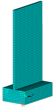
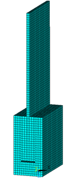
Effect of viscoelastic material on blade vibration and its damping performance is mainly researched. A simplified model of blade is adopted to draw a direct conclusion. The results can also be applied to actual aero-engine blades. According to the discussion in Chapter 2, Solid186 element is adopted for straight mortise blade and volume sweep method is selected to divide mesh. Finite element model after mesh division is shown in Figure 2. Element size is set to 1.5mm. In Figure 2(a), there are 5778 elements in blade and 6075 elements in mortise. In Figure 2(b), there are 4428 elements in blade and 2187 elements in mortise.
|
|
| (a) Common groove blade | (b) Dovetail groove blade |
| Figure 2. Finite element models of blades | |
For blade without viscoelastic block shown in Figure 2(b), there is a contact between blade and mortise side. Surface contact pairs are needed to make blade and mortise connect better. For blade that viscoelastic damping block is added to mortise sides shown in Figure 4(a), viscoelastic block is in contact with mortise sides. In order to connect two parts of different materials, volumes glue command in ANSYS software is required. Force will pass through blades for the combined structure that viscoelastic block has been added. Two surface contact pairs are established. For blades that viscoelastic damping block is added between blade bottom and mortise shown in Figure 4(b), there is a contact between viscoelastic damping block and mortise, which should be coupled through degree of freedom of overlapping joint.
3.2 Modal and harmonic response analysis
In actual blade installation, the interaction between blade and mortise needs to be pre-stressed to simulate centrifugal load. However, suppression effect of viscoelastic block on blade vibration is mainly discussed, so pre-stress has not been applied in order to simplify analysis. The fixed constraint is selected as boundary condition and blades are constrained on mortise bottom. Block Lanczos is used as modal extraction method. Modal analysis is carried out after defining boundary conditions. In case of undamped free vibration, the following dynamic equation is satisfied.
|
|
(13) |
Since free vibration of any elastic body can be decomposed into a series of simple harmonic vibration, solution of simple harmonic vibration for equation (13) is expressed as
|
|
(14) |
Taking equation (14) into (13) can get
|
|
(15) |
Because of free vibration, amplitude of each point in the structure is not zero, so the determinant value in above bracket must be equal to zero.
|
|
(16) |
Analysis shows that calculation of natural frequency comes down to an eigenvalue problem. Eigenvalues can be obtained by solving equation (17). The corresponding eigenvectors are . is natural circular frequency of i order, where i ranges from 1 to number of degrees of freedom. So natural frequency is . In order to represent dynamic response of the structure, many orders’ data are needed. Here, suppression effect of viscoelastic block on blade vibration is mainly discussed, in which high order’s data have little effect. So, only ten orders’ data will be extracted. Modal analysis of blades is solved by Block Lanczos method and natural frequency from 1 to 10 orders is obtained for blades with and without viscoelastic block. And viscoelastic block is added on mortise sides. Natural frequency of blades is given in Table 3.
| Order | 1 | 2 | 3 | 4 | 5 | 6 | 7 | 8 | 9 | 10 | |
| No block is added | 348.53 | 1326.9 | 2145.9 | 4365.2 | 4402.8 | 5780.8 | 7375.1 | 7997.2 | 8526.0 | 10400 | |
| Block is added | 344.49 | 1316.2 | 2119.6 | 2703.8 | 4323.0 | 5798.0 | 7390.1 | 8369.3 | 8417.0 | 10216 | |
After natural frequency is obtained by modal analysis, harmonic response is carried out. There are three methods to solve harmonic response in ANSYS software such as complete method, reduction method and mode superposition method. Based on previous analysis of harmonic response, modal superposition method should be used. At the top of blade, a sine load which amplitude is 0.5g is applied and nodes at the tip are selected to draw frequency-displacement curves.
4. Results and discussion
4.1 Effect of viscoelastic block parameters on blade vibration reduction
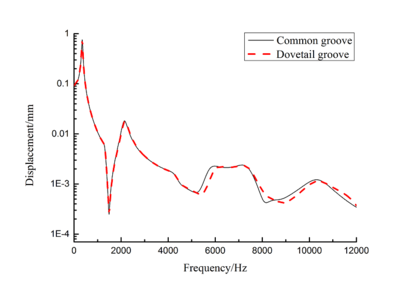
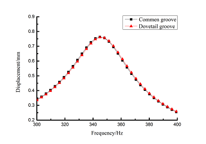
Free layer damping is the damping layer by adding damping material block to a blade surface directly. But blade structure used in this paper is a sandwich structure when mortise is added to blades. According to [21], this kind of damping treatment is the constrained layer damping. As for the constrained layer damping, loss factor and attenuation of frequency response amplitude is main criterion to evaluate the damping performance [21]. So, loss factor and frequency-displacement diagram of blade are mainly researched in the following study.In order to facilitate research, a more direct blade model should be established at first. Here, models of common groove blade and dovetail groove blade are established. Finite element model of common groove blade is shown in Figure 2(a) and that of dovetail groove blade is shown in Figure 2(b). Vibration displacement data of blade tip is extracted by harmonic response analysis and the frequency-displacement curves in 0-12000Hz ranges are drawn by Origin software as shown in Figure 3. Due to the vast amplitude difference across frequency range, logarithmic scale is used on vertical axis. It can be seen that vibration curves of above two blades are very close, so the shape of mortise has little effect on vibration response. Because dovetail groove is closer to actual shape of blade than common groove, so it is selected to carry out the following study.
| (a) Frequency-displacement curves from 1 to 10 orders |
| (b) First order frequency-displacement |
| Figure 3. Frequency-displacement curves of blades with different shape of mortises |
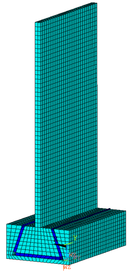
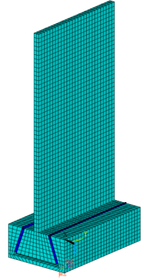
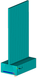
According to previous analysis, influence of different adding position and thickness of viscoelastic block on blade damping will be studied. Firstly, model of dovetail groove blade is established. Viscoelastic damping blocks were added to mortise side, bottom as well as both side and bottom of mortise, respectively. Thus four different models of blade were established including no viscoelastic damping block. Finite element models of blades with different adding position of viscoelastic block are shown in Figure 4. In Figure 4(a), there are 4698 elements in blade, 1782 elements in mortise and 432 elements in viscoelastic block. In Figure 4(b), there are 4428 elements in blades, 2268 elements in mortise and 270 elements in viscoelastic block. In Figure 4(c), there are 4428 elements in blades, 1809 elements in mortise and 945 elements in viscoelastic block.
|
|
|
| (a) Mortise side | (b) Mortise bottom | (c) Both side and bottom of mortise |
| Figure 4. Finite element models of blades with different adding position of viscoelastic block | ||
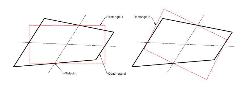
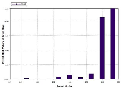
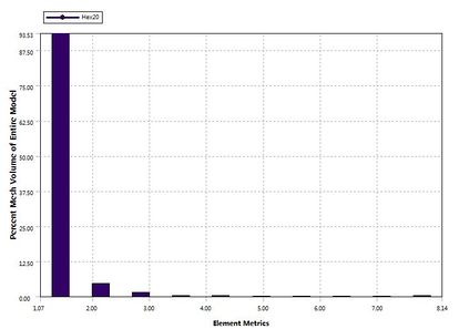
In order to ensure accuracy of calculation results, element quality needs to be checked before calculation. Because mesh change of blade is more complex when viscoelastic block is added to both side and bottom of mortise. So, mesh quality of blade is checked. There are many mesh metrics used to check such as element quality, aspect ratio, Jacobian ratio, warping factor and so on. All of them can be extracted by ANSYS. Here, only the element quality and aspect ratio are represented. Element quality is a mesh metric based on the ratio of the volume to the edge length for a given element. It ranges from 0 to 1 and number 1 is the best. Aspect ratio for quadrilaterals shown in Figure 5 is the maximum ratio of the longest side to the shortest side of two rectangles, in which are built through connecting four side midpoints of quadrilateral of element mesh. At the same time, the other mesh metrics also have been checked and show that the element quality in this paper is good.
| Figure 5. Aspect ratio for quadrilaterals |
The charts of mesh quality and aspect ratio are shown in Figure 6. It can be seen that element quality values exceeding 90 percent elements is higher than 0.85. And aspect ratio of 93 percent elements is lower than 1.5. The mesh quality is good and calculation results will be accurate.
| (a) Element quality |
| (b) Aspect ratio |
| Figure 6. Charts of element quality and aspect ratio |
Then modal analysis is used to obtain natural frequency from 1 to 10 orders of the four blades. Natural frequency is given in Table 4.
| Adding position | 1st order | 2nd order | 3rd order | 4th order | 5th order | 6th order | 7th order | 8th order | 9th order | 10th order | |
| No block is added | 348.53 | 1326.9 | 2145.9 | 4365.2 | 4402.8 | 5780.8 | 7375.1 | 7997.2 | 8526.0 | 10400 | |
| Mortise Side | 344.49 | 1316.2 | 2119.6 | 2703.8 | 4323.0 | 5798.0 | 7390.1 | 8369.3 | 8417.0 | 10216 | |
| Mortise Bottom | 347.14 | 1322.7 | 2153.6 | 4353.5 | 4796.3 | 5974.5 | 7404.0 | 8525.7 | 10346 | 11840 | |
| Both the side and bottom | 346.77 | 1320.2 | 2148.1 | 4341.2 | 4905.4 | 5944.0 | 7401.0 | 8481.8 | 10329 | 11690 | |
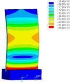
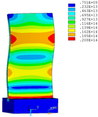
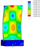
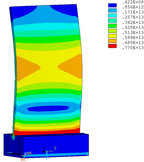
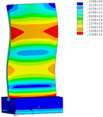
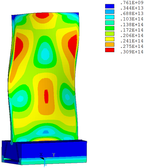
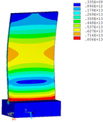
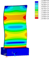
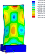
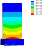
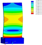
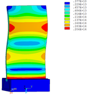
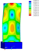
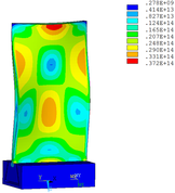
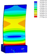
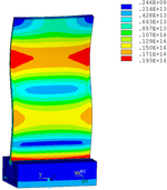
Distribution diagrams of Von Mises stress for natural frequency in 1st, 3rd, 6th and 10th orders are shown in Table 5. It is equivalent stress. It can be seen that the maximum stress is mainly located in the blade root. The maximum stress of blade with viscoelastic block added to blade side is the smallest in the same condition and decreases about 30% compared with that without viscoelastic block in 1st order.
| Order | 1 | 3 | 6 | 10 |
| No block is added | 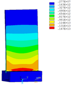
|
|
|
|
| Side of mortise | 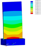
|
|
|
|
| Bottom of mortise | 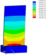
|
|
|
|
| Both side
and bottom |
|
|
|
|
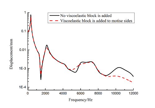
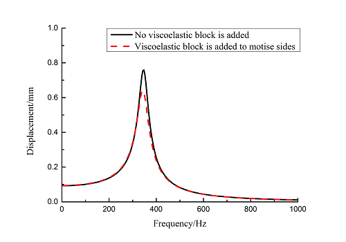
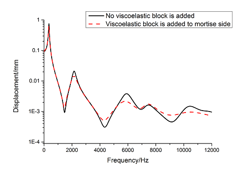
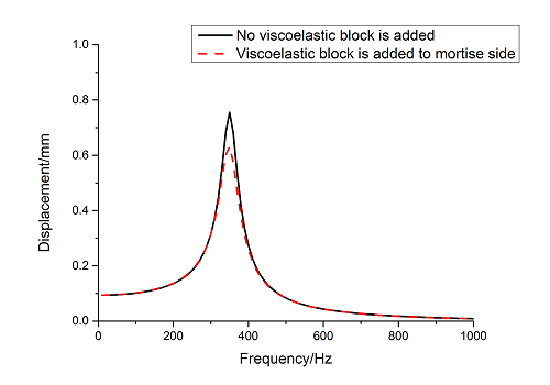
Frequency-displacement curves of blade with viscoelastic block added to mortise sides are obtained in 0~12000 Hz ranges by harmonic response analysis as shown in Figure 7. It can be seen that the maximum displacement of blade decreases about 15.6% when viscoelastic block is added. The larger vibration displacements are obtained by extracting nodes data of the 1st, 3rd, 6th and10th orders at the tip of blades.
| Figure 7. Frequency-displacement curves from 1 to 10 orders of blades with and without viscoelastic block added to mortise sides |
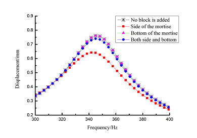
Frequency-displacement curves of above orders are shown in Table 6 for different adding position of viscoelastic blocks. It can be seen that when viscoelastic block is added to mortise side, the maximum displacement of each order is smaller than that of other blades .
| Order | Frequency-displacement curves |
| 1 | |
| 3 | 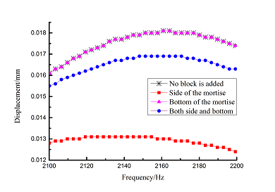
|
| 6 | 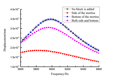
|
| 10 | 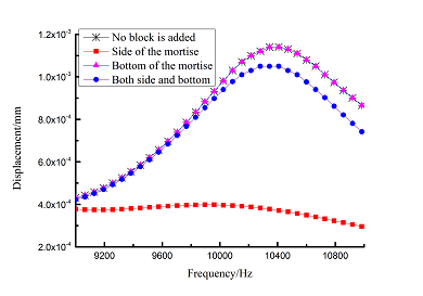
|
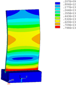
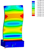
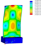
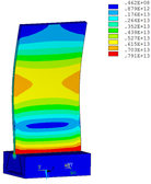
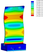
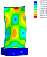
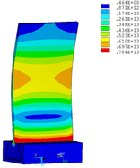
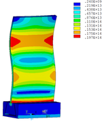
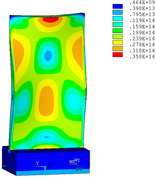
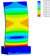
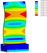
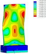
Then influence of different thickness of viscoelastic block on blade vibration reduction is analyzed. Thickness of viscoelastic blocks is chosen as 0.2mm, 0.4mm, 0.6mm, 0.8mm and 1.0mm, respectively. Modal and harmonious response analysis is carried out. Natural frequency and loss factor of blades from 1 to 10 orders are obtained. Natural frequency is given in Table 7. Von Mises stress distribution of blades is shown in Table 8 for natural frequency of 1st, 3rd, 6th and 10th orders.
| Thickness/mm | 1st order | 2nd order | 3rd order | 4th order | 5th order | 6th order | 7th order | 8th order | 9th order | 10th order | |||||||||||
| No block is added | 347.14 | 1322.7 | 2153.6 | 4353.5 | 4797.4 | 5974.5 | 7404.0 | 8525.7 | 10346 | 11840 | |||||||||||
| 0.2 | 346.50 | 1320.4 | 2145.8 | 3962.5 | 4343.0 | 5939.1 | 7400.8 | 8493.0 | 10332 | 11710 | |||||||||||
| 0.4 | 346.03 | 1319.0 | 2139.3 | 3504.2 | 4336.7 | 5906.1 | 7398.3 | 8471.1 | 10322 | 11516 | |||||||||||
| 0.6 | 345.49 | 1317.8 | 2132.5 | 3182.9 | 4331.3 | 5871.4 | 7395.7 | 8451.6 | 10224 | 10307 | |||||||||||
| 0.8 | 344.99 | 1317.0 | 2126.1 | 2923.6 | 4327.0 | 5836.0 | 7393.0 | 8434.4 | 9208.8 | 10282 | |||||||||||
| 1.0 | 344.49 | 1316.2 | 2119.6 | 2703.8 | 4323.0 | 5798.0 | 7390.1 | 8369.3 | 8417.0 | 10216 |
| Order | 1 | 3 | 6 | 10 |
| 0.2 | 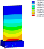
|
|
|
|
| 0.4 | 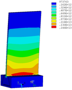
|
|
|
|
| 0.6 | 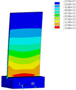
|
|
|
|
| 0.8 | 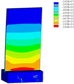
|
|
|
|
| 1.0 | 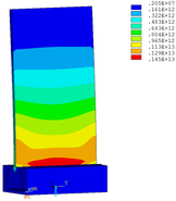
|
|
|
|
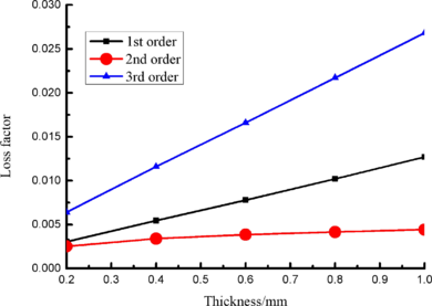
Change rule of loss factor is shown in Figure 8 for the first three orders. Frequency-displacement curves of each order are shown in Table 9. It can be seen that the larger thickness of viscoelastic block, more effective suppressing vibration of blades will be.
|
| Figure 8. Influence of viscoelastic block thickness on loss factor of Blades |
| Order | Frequency-displacement curves |
| 1 | 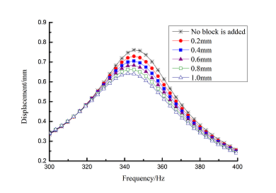
|
| 3 | 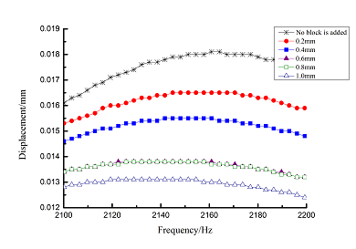
|
| 6 | 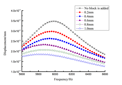
|
| 10 | 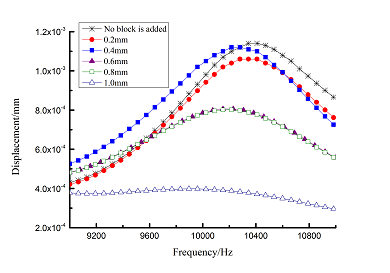
|
4.2 Parameters effect of viscoelastic damping material on blade vibration reduction
Loss factor of blade is the main parameter to evaluate the effect of damping performance of viscoelastic material. The modeling method of strain energy can be used to obtain loss factor of blade and assess the effect on suppressing vibration when different parameters of VDM are changed. As for constrained layer damping, loss factor of blade with damping material is related to thickness of damping layer, elastic modulus and loss factor of VDM. Because thickness has been discussed above, so here loss factor and elastic modulus will be researched how to effect on damping performance
Elastic modulus of material was chosen as 0.5 GPa, 0.75 GPa, 1.0 GPa, 1.25GPa, 1.5 GPa, 1.75GPa and 2.0 GPa, respectively. Modal and harmonic response analysis is carried out and loss factor of blade from 1to10 orders is obtained. Change rule of loss factor is shown in Figure 9 for the first three orders. Loss factor in 1st order increases about 205.8% when elastic modulus is 0.5GPa compared with that when elastic modulus is 2.0GPa. It can be seen that the smaller elastic modulus, the larger loss factor of blade will be.
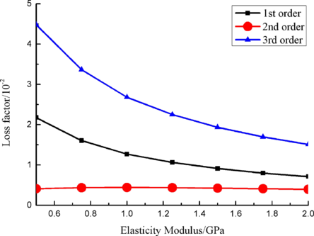
|
| Figure 9. Influence of elastic modulus of VDM on loss factor of blades |
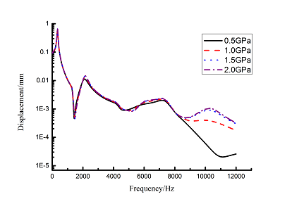
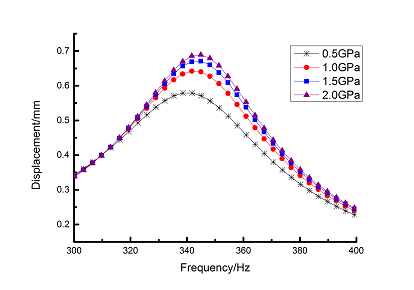
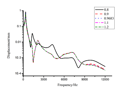
Frequency-displacement curves in 0-12000Hz ranges with different elastic moduli are obtained by harmonic response analysis as shown in Figure 10(a). It can be seen that the maximum displacement happens in the 1st order of blade. Displacement data in the first order of natural frequency are extracted and Origin curves are shown in Figure 10(b). Comparing with the blade that elastic modulus is 2.0 GPa, the maximum displacement in the 1st order decreases about 16% when elastic modulus is 0.5 GPa.
| (a) From 1 to 10 orders | |
| (b) The first order | |
| Figure 10. Frequency-displacement curves of blade with different elastic modulus of VDM | |
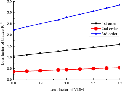
Loss factor of viscoelastic material is chosen as 0.8, 0.85, 0.9, 0.9683, 1.0, 1.05, 1.1, 1.15 and 1.2, respectively. Modal and harmonic response analysis is carried out. The loss factor from 1 to 10 orders of blade is obtained by modal analysis. Change rule of loss factor is shown in Figure 11 for first three orders. It can be seen that the larger loss factor of viscoelastic material, the larger loss factor of blade in each order.
| Figure 11. Loss factor of blade with different loss factor of VDM |
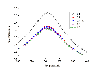
Frequency-displacement curves in 1-12000Hz ranges are obtained by the harmonic response analysis as shown in Figure 12(a). It can be seen that displacement reduction is obvious in low frequency ranges. Harmonic response data of the maximum displacement for first order natural frequency are extracted and Origin curves are shown in Figure 12(b). It can be seen that displacement reduction is obvious and about 22% when loss factor of viscoelastic material increases from 0.8 to 0.9.
| (a) From 1 to 10 orders | |
| (b) The first order | |
| Figure 12. Frequency-displacement curves of blade with different loss factor of VDM | |
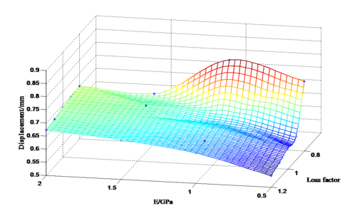
Influence of single material parameter on blade vibration reduction is discussed above. It shows that parameters of viscoelastic damping material play an important role in damping performance. It is necessary to make a reasonable choice of material parameters for damping performance of VDM. Changing the elastic modulus and loss factor at the same time, harmonic response data of different elastic modulus and loss factors are extracted. The maximum vibration displacement under different parameters is obtained as given in Table 10.
These data were used to draw the MATLAB scatter diagram as shown in Figure 13. It can be seen that vibration displacement is the minimum when loss factor is chosen as 1.2 and elastic modulus is 0.5GPa. Its amplitude decreases 34.6% comparing with that when loss factor is chosen as 0.8 and elastic modulus is chosen as 1.0GPa.
| Loss factor
E/GPa |
0.8 | 0.9 | 0.9683 | 1.1 | 1.2 |
| 0.5 | 0.766080 | 0.590879 | 0.579677 | 0.559249 | 0.544685 |
| 1.0 | 0.832404 | 0.649887 | 0.642378 | 0.626752 | 0.615797 |
| 1.5 | 0.687478 | 0.677986 | 0.671654 | 0.659775 | 0.651034 |
| 2.0 | 0.702372 | 0.694605 | 0.689400 | 0.679582 | 0.672312 |
| Figure 13. Three-dimensional scatter diagram of the maximum displacement of blades |
Additionally, centrifugal force may have some effect on the damping performance of viscoelastic material. Here, angular velocity of 600rad/s is applied to Y axis of dovetail groove blade shown in Figure 2(b) with and without viscoelastic block. Then model analysis with pre-stressed and harmonic response analysis is analyzed. When centrifugal force is not considered, the displacement in 0~12000 Hz frequency ranges is shown in Figure 7 and the maximum displacement is shown in Figure 14. When centrifugal force is considered, the displacement in 0~12000 Hz frequency ranges is shown in Figure 15(a) and the maximum displacement is shown in Figure 15(b).
| Figure 14. The maximum displacement of blades with and without viscoelastic block added to mortise sides when centrifugal force is considered |
| (a) Frequency-displacement curves from 1 to 10 orders of blades with and without viscoelastic block added to mortise sides | |
| (b) The maximum displacement of blades with and without viscoelastic block added to mortise sides | |
| Figure 15. Frequency-displacement curves when centrifugal force is considered | |
It can be seen that the maximum displacement of blade with viscoelastic block decreases by 18.6% compared with that without viscoelastic block when centrifugal force is not considered. The viscoelastic material also has effect on suppressing vibration of blade when centrifugal force is considered. But the maximum displacement of blade with viscoelastic block only decreases by 16.3% compared with that without viscoelastic block. Based on above analysis, viscoelastic material will reduce the damping performance when centrifugal force is considered. But the decrease magnitude is so small under angular velocity of 600rad/s.
5. Conclusions
Against the background to suppress vibration response of aircraft blades by adding viscoelastic damping block, effects of the adding position and thickness, viscoelastic damping material parameters as well as mortise shape on damping performance have been researched. Through above analysis, the following conclusions can be drawn.
1. When mortise shape is different, vibration displacement of both common groove and dovetail groove blades is almost same. So, mortise shape has little influence on blade vibration, which is not a major consideration when it is designed to reduce blade vibration.
2. Viscoelastic damping block can be used to reduce blade vibration. However, the damping effects are different under different adding position of viscoelastic block. When viscoelastic block is added to mortise side, vibration reduction effect is the best and not obvious when adding to mortise bottom. When thickness of viscoelastic block is changed, the damping effect is changed correspondingly.
3. Parameters of viscoelastic damping material have great influence on the vibration of blade. When elastic modulus and loss factor of material is changed, vibration effect of blade is changed correspondingly. The smaller elastic modulus, the smaller vibration displacement and the better vibration reduction effect will be. The larger loss factor, the smaller vibration displacement and the better vibration reduction effect will be.
4. Performance of viscoelastic material on reducing blade vibration should assess the effects of various factors comprehensively. Change of elastic modulus and loss factor at the same time is more effective to improve the damping performance of blade than only change of single parameter.
Acknowledgements
This study is supported by the National Natural Science Foundation (No: 51475369).
References
[1] Huang Y.X., Chen G.X. The structure crack detection of aero-engine compressor based on modal analysis. Science & Technology Information, (23):83-84, 2011 (in Chinese).
[2] Zhang W., Feng Z.Q., Guo X.Y. Nonlinear vibration of aero-engine compressor blades. Science China Physics, Mechanics & Astronomy, (4):345-362, 2013.
[3] Zhao Y.F. Properties and applications of ZN series viscoelastic damping materials. Aerospace Materials & Technology, (31):19-23, 2001.
[4] Williams M.L. Structural analysis of viscoelastic materials. AIAA Journal, 2(5):785-808, 2012.
[5] Zhang F., Guo M., Xu K. et al. Multilayered damping composites with damping layer/constraining layer prepared by a novel method. Composites Science & Technology, 101(101):167-172, 2014.
[6] Shokrieh M.M., Najafi A. Damping characterization and viscoelastic behavior of laminated polymer matrix composites using a modified classical lamination theory. Experimental Mechanics, 47(6):831-839, 2007.
[7] Fan R.P. Experimental study of viscoelastic damping materials for vibration and noise control within railway vehicles. Journal of Mechanical Strength, 32(2):188-195, 2010 (in Chinese).
[8] Yang J.S. Vibration and damping characteristics of hybrid carbon fiber composite pyramidal truss sandwich panels with viscoelastic layers. Composite Structures, (106):570-580, 2013.
[9] Robinson M.J., Kosmatka J.B. Embedding viscoelastic damping materials in low-cost VARTM composite structures. Proceedings of SPIE-The International Society for Optical Engineering, 5760:349-360, 2005.
[10] Zhou X.Q. Simplified-super-element-method for analyzing free flexural vibration characteristics of periodically stiffened-thin-plate filled with viscoelastic damping material. Thin-Walled Structures, (94):234-252, 2015.
[11] Martinez M.A., Elejabarrieta M.J. Dynamic characterization of high damping viscoelastic materials from vibration test data. Journal of Sound & Vibration, 330(16):3930-3943, 2011.
[12] Trindade M.A. Optimization of passive constrained layer damping treatments applied to composite beams. Latin American Journal of Solids & Structures, 4(1):19-38, 2007.
[13] Wang H.J., Chen L.W. Vibration and damping analysis of a three-layered composite annular plate with a viscoelastic mid-layer. Composite Structures, 58(4):563-570, 2002.
[14] Montemurro M., Vincenti A., Yao K., et al. A two-level procedure for the global optimization of the damping behavior of composite laminated plates with elastomer patches. Journal of Vibration & Control, 21(9):1778-1800, 2014.
[15] Tan D.H., Yu H. Viscoelastic Materials Used for Vibration and Noise Control. Marine Electric & Electronic Engineering, (2):63-66, 2015.
[16] Zhou S.C., Liu J.H. Dynamic modeling and engineering application of viscoelastic damping elements. Journal of Astronautics, (4):1346-1350, 2009.
[17] Lu C.H., Bai H.B. Study on constitutive model of viscoelastic material. Polymer Materials Science & Engineering, 23(6):28-31+35, 2007.
[18] Gamonpilas C., McCuiston R. A non-linear viscoelastic material constitutive model for polyurea. Polymer, 53(17):3655-3658, 2012.
[19] Park S.W., Schapery R.A. Methods of interconversion between linear viscoelastic material functions. Part I—a numerical method based on Prony series. International Journal of Solids & Structures, 36(11):1653-1675, 1999.
[20] Zhang H.L., Zhou J.P. Viscoelastic stochastic finite element simulation of solid propellant grain with random Poisson’s ratio. Journal of Propulsion Technology, 22(3):245-249, 2001.
[21] Xiao S.Y., Wang H., Ruan Z.Q. Test Assessment Method of Damping Property of Viscoelastic Damping Materials. Chinese Journal of Ship Research, 9(4):84-87, 2014.
Document information
Published on 08/02/19
Accepted on 16/09/18
Submitted on 21/01/18
Volume 35, Issue 1, 2019
DOI: 10.23967/j.rimni.2018.09.002
Licence: CC BY-NC-SA license
Share this document
Keywords
claim authorship
Are you one of the authors of this document?
