Summary
Sun Valley, the landmark building of World Expo in Shanghai, which has free surface with single-layer reticulated shell structure, is a typical complex structure. CAD/CAM integrated information system to design is used for the complex structure; however, it is a very rigorous process to be used widely. The relevant technology of the Sun Valley is not open to the public at present, so we try to use BIM technology to model the Sun Valley, including architecture modelling and structure analysis. By analysis of the Sun Valley structure using this method, it is proved that the problems in modelling may be solved by writing some script codes in Rhino software and the stability of the model can also be analyzed. The new approach is viable and effective in combination with different softwares such as Rhino, Revit, and Midas in solution of the complex shaped surfaces’ structure for modelling and calculation.
Keywords
Sun Valley ; BIM technology ; Bar angle ; Stability analysis ; Write plug-ins
Introduction of Project
The Expo Axis and its boulevard is one of the five buildings which remain after the end of the world expo to form the centre of a new urban district of Shanghai. And Sun Valley is the core of the axis. The exterior of Sun Valley is made up of the free curved cylindrical lattice shell structures, which make the building look vivid. Sun Valley integral structure has 10,348 units of nodes interconnected and more than 31,000 root bars connected together with each other. The top diameter of the structure is 97 m; the bottom diameter is 20 m. It has a great number of components with different types of nodes. The angle of the keel is determined by the normal direction of its facet and each keel is not on the same facet. Meanwhile, the structure should achieve the seamless construction; the deviation for each node unit should be less than 0.5 mm, and the deviation angle should be less than 0.25°. The integral structure is precise and artistic.
Sun Valley has a complex and particular structure, with the traditional modelling and structural analysis software such as Auto CAD and PKPM being difficult to establish a precise model of the structure. At the same time because of the number of the Sun Valley component, if completely artificial detail is used, not only will there be huge workload but also the efficiency of drawing process will be low (Jia-chun, 2011 ).
BIM is a 3D-based framework designed to integrate and digitize complete building information so as to express all the building components and their relationships. The goal of BIM has existed for at least 30 years and various standards have been published. Existing literature provide individual aspects of BIM, such as the need for data exchange standards, the future potential and inter-organizational usage of BIM. Usage of BIM technology can turn pure geometry performance to full information model integration; from completing the project individually to completing it collectively; from discrete step-by-step design to whole-process integral design based on the same model. Using this design idea, it can be more efficient to solve the problem and change the problem for single use by targeting the limitations of software development.
Rhinoceros (typically abbreviated Rhino, or Rhino3D) is a commercial 3D computer graphics and computer-aided design (CAD) application software. Rhinoceros geometry is based on the NURBS mathematical model, which focuses on producing mathematically precise representation of curves and freeform surfaces in computer graphics. By using Rhino, a high precision surface can be established. Then Rhino is used to build the Sun Valley BIM model, combining the BIM model with Midas structure operation function. Therefore, Sun Valley, which is a complex structure and based on BIM technology, can achieve stability analysis. After verifying the feasibility, this method, based on the technology of the BIM, may be applied to do the stability analysis of other complex structures.
Analysis on structure of bar angle
The structural analysis with Sun Valley, firstly the model of Sun Valley BIM, needs to be built through the method of Rhino, then via BIM model to generate a DXF file. In the end, the centreline data, which is located by structural unit DFX file, are imported to the Midas calculation software to process the stability analysis which is positioned as centreline data. Because the cross-section is non-circular tube structure, the imported model through DXF file does not include information about unit cross-sectional direction angle. In this situation, sectional direction parallel to the surface direction cannot be guaranteed. Sun Valleys infrastructure keel is a rectangular unit. In the implementation process, when the model established in Rhino import, DXF files import to the Midas GEN through the directions of the corner, which have all changed into the normal direction of the X –Y plane rather than the double-curved surface normal direction of Sun Valleys structure.
In this case, the designer who is to ensure the reliability of structural calculations often applies the amplification factor of safety to ignore the impact of cross-section corner. This approach is inaccurate and uneconomical, even will be a security risk sometimes (Jia and Cai-qin, 2008 ).
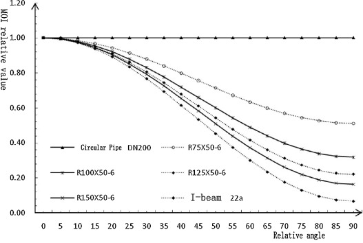
The same section in different cross-sectionals exists as a major difference between the angles (when the angle between the load direction and the vertical direction of angle strong axis is 90°, perpendicular is recorded as 0°) and corresponding flexural behaviour (moment of inertia). It is assumed that inertia moment of the strong axis data is 1. The fact that rectangular tubes are more sensitive to the sectional corner can be seen from Picture 2-1 . When angle of the cross-section is 40°, the relative inertia moment will reduce 80–60% of the original data. With a high aspect ratio selected, inertia moment will reduce faster. Obviously, it is necessary to enter the exact angle during the period of sectional structure modelling.
Solutions of bar angle problems
With what is known from Midas GEN software, the local default directions of the two-axis and three-axis are determined by the relationship with the partial 1-axis and integral Z -axis; local 1–2 plane which is perpendicular to the XY plane parallel to the Z axis; local 3-axis which is a horizontal axis is in the XY plane.
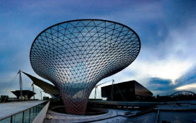
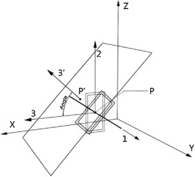
When the default orientation angle of the lever is determined in theory, the direction of the cross-section of the rod disposed strong axis (local 2-axis) on the surface of the actual project needs to be found. For the space bar member unit, modelling rod unit relative to the surface is an approximation of the approach at the time of calculation; the lever unit will be calculated by approaching a straight line. According to calculations experience, the midpoint of the rod is often used to the position of the surface of the nearest point of the surface normal direction, as the local 3-axis direction of the rod member target (some projects use a 2-axis). So we will make software defaults to the local 3-axis direction and target local 3-axis direction in the plane of the cross-section of the projection angle can be adjusted so that it is corrected to the right degree, geometric calculations indicate the method, sees corner computing schematic cross section of Picture 1-1 (Min et al., 2010 ).
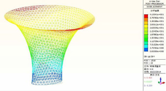
Picture 1-1.
Design sketch of Sun Valley.
Picture 2-1.
Diagram of section angle and bending performance.
As shown in Picture 3-1 , P point is the midpoint of the rod unit. P ′ point is to the nearest point on the surface corresponding to 3′-axis direction of the local axis 3-axis target (surface normal); the “angle” shown in the figure is demand angle ( Wei et al., 2014 ).
Picture 3-1.
Cross-section angle calculation principle.
Therefore, secondary development is used as the method in Rhino to solve this problem, the specific operation process: First, use “Rhino.Mid Point” to get the coordinates of the midpoint of the rod means; Get the rod axis direction (local 1 axis) by “Rhino. Curve Evaluate”; use “Rhino.Surface Closest Point” to get the nearest point on the surface of the axis corresponding to the midpoint. Then, use “Rhino Surface Normal” position to obtain the corresponding point in the direction of the surface normal; use “Rhino. Vector Cross Product” to determine the vector cross product direction lever unit; use “Rhino. Plane From Frame” to determine computing the angle of the projection screen needs; and finally use the “Rhino.Angle” to calculate the angle values. Completion of the above steps, and after the angle was calculated, usage of the “Rhino. Object Name” function put the angle data stored as one of the parameters of the lever, and then used the MGT to command stream output format lever unit corresponding text and finally complete the calculation model export (Hong et al., 2010 ).
Analysis of stability
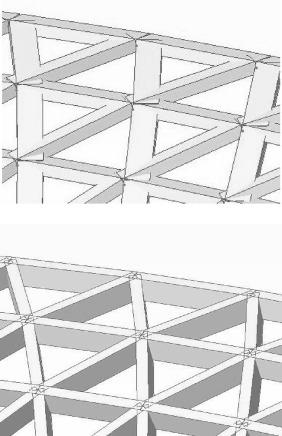
To further verify the impact of the lever angle stability on the overall structure, the Sun Valley model stability in two different angles of the lever is analyzed. Sun Valley is mainly loaded by keel weight, curtain weight, wind loads and seismic loads. The overall model and the actual structure at a 2:1 specification modelling are used in the operations. The specifications for keel member are 210 mm × 100 mm × 3 mm and the material is steel. Selection of steel is Q390, bulk density is 78 kN/m3 , and elastic modulus is 207 GPa. Specification of the curtain drawn is an equilateral triangle with 1000 mm of side length and 3 mm of thickness (Hong et al., 2010 ). In the calculation, the total weight of the walls is distributed to each node with the force of 0.1428 kN, and the direction is Z downwards. Wind load is divided into X and Y direction load. Because Sun Valley has profiled surface, wind load needs to be reduced according to the wind projection surface and we need to put equivalent load to the keel node. The basic wind pressure is 0.35 kN/m2 . Structure shape coefficient of wind load needs to be calculated according to the model shape. Model shown below, for example, calculated that the node X direction of the wind load is 0.46 kN and Y direction of the wind load is 0.49 kN. According to “Steel seismic norms”, seismic loads are chosen as Shanghai region fortification intensity 7°; the basic seismic acceleration is 0.10 g ( Picture 4-1 and Picture 4-2 ).
Picture 4-1.
Two kinds of forms which of the adjustment in Midas GEN before and last.
Picture 4-2.
Displacement nephogram of the adjustment.
According to Midas gen calculation results, the most adverse conditions were selected. Then, 10 nodes were singled out and operation analysis was done.
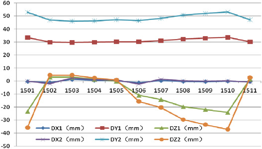
Midas gen calculations show that the most unfavourable conditions for the load “1.20D + 1.4Y direction of the wind load” working conditions. In Fig. 4-3 , in the most adverse conditions, the error in the Y direction was very obvious, when the lever angle was not adjusted, and the displacement distance was 20 mm shorter than when the lever section was adjusted, leading to large errors (Fig. 4-4 ).
|
|
|
Figure 4-3. The node displacement contrast analysis diagram. |
|
|
|
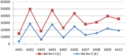
Figure 4-4. Axial force contrast analysis diagram. |
The results found that the error by simply increasing load and changing lever to reduce the cross-sectional form would not be reduced. On the contrary, increasing the load and changing the lever-section would change the whole structures forces condition.
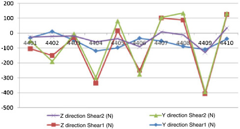
Similarly, comparing axial force with shear in ten members in the same position, as shown in Figure 4-5 and Figure 4-6 , there is large error in the shaft shear force of the rod member. Meanwhile the error in shear, which results in torque direction lever changes, has a greater impact on the structures forces condition.
|
|
|
Figure 4-5. Shear contrast analysis diagram. |
|
|
|
Figure 4-6. Stress analysis diagram. |
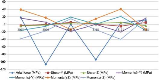
After adjusting the angle of rub member, the results of the calculation of the reaction force to the maximum member forces node 116 as the centre of six rods stability analysis. The results show that, because the number 3046 lever is in the lower part of the larger part of the model surface curvature, therefore, it is a greater stress rod. Other most unfavourable positions of the lever member number are as follows: 3045, 3046, 3047, 3115, 3121, and 3128 of structures.
This six bars stress node side is shown in Fig. 4-6 . 3–4 mm thick, rectangular steel pipe allows stress at 100 °C is 206 Mpa; structural stability ultimate load factor up to 1.6. Due to the fact that Sun Valley is a single layer lattice shell cantilevered structure, according to the allowable deflection “spatial grid structure technology point of order”, a single-layer lattice shell structure is a cantilevered structure with cantilevered span of 200, corresponding to the present model of 20,000 mm/200 = 100 mm. Under “1.2D + 1.4Y direction of the wind load,” the most unfavourable load case, the maximum displacement of the structure is 41.2 mm, less than 100 mm, which can meet the regulatory requirements (Hajjar, 2002 and Yang et al., 2009 ).
Conclusion
By comparing two different situations in which the analysis of structures force includes two angles of the lever, it is obvious that if the corners’ problem is not resolved, using default angle, directly from finite element analysis software, processing the analysis of integral structures force will lead to imprecision. And this deviation is difficult to control by changing the other parameters. Thus, in the structure analysis and calculation, especially for complex structure, its angular direction of the rod is an important parameter affecting the performance of the overall structure. In the process of modelling and computational analysis, the angular direction needs strict control.
BIM design is a new technology with innovative design logic. It is an efficient way to combine the decentralized works together through three-dimensional model of BIM. With such incredible interoperability, it makes architectural design, structural design, construction design, and project budget form an integral part. In each step, the work-required data can be extracted based on BIM model, thereby greatly improving the work efficiency and saving operating costs.
Free curved cylindrical reticulated shell of Sun Valley posts high requirements to surface modelling, because traditional software cannot establish a high-precision free-form surface for such complex structures. However, some new types of BIM-based modelling software, building a high accuracy model for complex structure, can be a good solution to this problem. From the analysis above, it is clear that after solving the problem of the corner, analysis of structures force can reflect the actual situation of force.
In summary, so far, there is a lot of structural calculation software which cannot get accuracy requirements for abnormality structure. Via software such as Rhino, Revit, it is feasible to establish BIM models to solve complex structure modelling problems. Therefore, after conducting calculation analysis by means of structural calculation software, it will be a very advanced and efficient method to adjust the model by the further development approach.
Conflict of interest
The author declares that there is no conflict of interest.
References
- Hajjar, 2002 J.F. Hajjar; Composite steel and concrete structural systems for seismic engineering; J. Constr. Steel Res., 58 (2002), pp. 703–723
- Hong et al., 2010 W.K. Hong, S.I. Kim, S.C. Park, J.M. Kim, S.G. Lee, K.J. Yoon, S.K. Kim; Composite beam composed of steel and pre-cast concrete (modularized hybrid system, MHS). Part IV. Application for multi-residential housing; Struct. Des. Tall Spec. Build., 19 (2010), pp. 707–727
- Jia and Cai-qin, 2008 Z. Jia, C. Cai-qin; MIDAS GEN in the application of special structure; The Twentieth High-Rise Building Structure Academic Conference Papers (2008)
- Jia-chun, 2011 C. Jia-chun; The research of overall stability analysis of Sun Valley of Expo Axis; J. Inf. Technol. Civil Eng. Archit. (2011)
- Min et al., 2010 C. Min, X. Dong, Z. Yang, S. Liang; Experimental research and finite element analysis on joints of Sun Valley steel structure for the Expo Axis project; J. Build. Struct. (2010)
- Wei et al., 2014 T. Wei, D. Shi-lin, G. Gang; Net shell structure considering bar instability process of the overall stability analysis; J. Build. Struct. (2014)
- Yang et al., 2009 H. Yang, Z. Chang, Z. Yang, Q. Zhang; Steel structure CAD/CAM integrated information system of Sun Valley of Expo Axis; Constr. Technol. (2009)
Document information
Published on 05/10/16
Licence: Other
Share this document
Keywords
claim authorship
Are you one of the authors of this document?
