Abstract
Recent achievements in the proactive turbine control, based on the upwind speed measurements, are described in a unified framework (as an extension of the tutorial [1]), that in turn represents a systematic view of the control activity carried out within the Swedish Wind Power Technology Center (SWPTC). A new turbine control problem statement with constraints on blade loads is reviewed. This problem statement allows the design of a new class of simultaneous speed and pitch control strategies based on the preview measurements and look-ahead calculations. A generation of a piecewise constant desired pitch angle profile which is calculated using the turbine load prediction is reviewed in this article as one of the most promising approaches. This in turn allows the reduction of the pitch actuation and the design of the collective pitch control strategy with the maximum possible actuation rate. Two turbine speed control strategies based on one-mass and two-mass models of the drivetrain are also described in this article. The strategies are compared to the existing drivetrain controller. Moreover, postprocessing technique that can be used for estimation of the turbine parameters with improved performance is also discussed. Postprocessing-based estimation of the turbine inertia moment is given as an example. All the results are illustrated by simulations with a wind speed record from the Hönö turbine, located outside of Gothenburg, Sweden.
Introduction
Proactive turbine control
The stochastic nature of the wind motivates the development of preview-based control strategies for both maximization of the turbine power and mitigation of the turbine loads. Preview information, for example, provided by a LIDAR-based measurement system (see Fig. 1 for details) can be used in different ways which in turn result in different performance of the turbine control system.
|
|
|
Figure 1. Preview measurements at a distance in front of the turbine. A laser beam (which serves as a reference beam) is focused toward a point which is located at a certain distance in front of the turbine, and a beam (which is a measurement beam) reflected back from dust particles, water droplets, and so on is detected. Wind movements advect the particles so that the measurement beam is slightly changed compared with the reference beam. This change is proportional to the wind speed and gives an opportunity for accurate wind speed measurements. This picture is reproduced from Stotsky and Egardt [4].
|
The achievements reported recently by the authors in[2-4] in the field of preview-based turbine control are described and summarized in this article in a unified framework. Look-ahead calculations, constraints on blade loads, robust drivetrain controllers, improvements of the pitch transients, as well as postprocessing techniques for estimation of the turbine parameters are the key elements of a new proactive control concept, described in this article in a tutorial fashion.
Model predictive control (MPC) is one of the most suitable proactive techniques based on the upwind speed measurements, see recent papers[5-7], and references therein. An MPC can successfully cope with rapid transients of the wind speed detected at a distance in front of the turbine. However, the resulting computational burden of MPC might be quite heavy, diminishing its advantages compared to simple and easy-to-implement control schemes.
The second method to use the preview information results in feedforward part of the control system (see recent papers [1], [3], [8, 9] and references therein) which is based on inversion of turbine model and utilized to proactively control the turbine as an alternative control method to MPC. This feedforward part is based on preprocessing of the wind speed signal and generation of a high-quality wind speed derivative signal, as well as on the prediction of future turbine loads and pitch angle [3].
Turbine control is typically divided into operating regions, where wind speed is the below- or above-rated speed. Collective pitch control is usually used for limitation of the turbine power when the wind speed is above rated and the generator torque control signal is saturated. Introduction of the bounds on the blade loads provide a unified description for both regions (below- and above-rated speed) [2].
Two drivetrain control strategies are described in this article. The first one is based on a simplified/one-mass drivetrain model [3]. The second one is based on a two-mass model which is suitable for control of drivetrains with significant flexibility of the drive shaft [2]. A comparative analysis is performed for two drivetrain controllers which are based on one-mass model [1][3].
Robust proactive control
Deviations between the wind speed measured at a distance in front of the turbine and the wind speed that arrives to the turbine site as well as inaccurate measurements of the wind speed at the turbine site necessitate the development of robust (with respect to the wind speed measurement errors) proactive control systems.
Proactive control is usually based on the expected wind speed, that is, the speed that is measured at a distance in front of the turbine and expected to arrive to the turbine site after some time. A classical frozen turbulence assumption which is used for the calculation of the expected wind speed might introduce additional significant inaccuracies in the preview information [10][11].
Deviations between the expected and actual wind speeds at the turbine site might be accounted in the feedforward part of the speed controller, where only the derivative of the upwind speed signal is used. Therefore the control system is robust with respect to the constant or slowly varying deviations between those two speeds [3]. Besides, a constant error in the derivative of the expected wind speed can be well compensated by the integral term of the feedback turbine speed controller that gives additional robustness to the system.
Unfortunately, the errors in the wind speed measurements delivered by the cup anemometer at the turbine site cannot be compensated in the speed control system and usually result in power reduction. However, those errors might be accounted in the pitch control loop. To this end, the concept of bounding of the blade loads, described above is used. The strategy includes the following three steps [4]: (1) load prediction/calculation is performed using the preview wind speed measurements in the first step; (2) the desired pitch angle profile is calculated in the second step with a specified upper bound on the flapwise bending moment; and (3) the majorization (overbounding) of the desired pitch angle profile with piecewise constant function is performed in the third step.
The desired piecewise constant pitch angle profile, which is known in advance, in turn allows: (1) a reduction of the blade pitch actuation, (2) a design of control system with high performance tracking capabilities, (3) a compensation of the errors in the upwind/wind speed measurements, as well as inaccuracies due to the frozen turbulence assumption.
Improving transients in the blade pitch control system
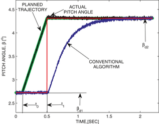
The performance of the blade pitch control system has a direct impact on the turbine mechanical loads. The constraint on the pitch actuation rate is the most significant limitation in the blade pitch actuation. The desired blade pitch angle profile calculated in preprocessing is a piecewise constant function of time with available values in preview allows accounting for rate limitation and improves the performance of regulation. The transient between two constant desired values of the blade pitch angle is described as a linear function of time with the maximal blade pitch rate. Availability of the preview information in combination with spline planning allows the proactive transient of the blade pitch angle with the highest possible rate [4].
Postprocessing perspective
Turbine parameters such as inertia, drivetrain damping factor and others might change with the turbine operating conditions. The inertia moment, for example, might change up to 15% with turbine icing in cold climate. Inertia moment can be estimated using turbine model and the generator speed measurements. Noise in the measurements of the generator speed is the main obstacle for real-time estimation of the inertia moment. Postprocessing method (as an alternative method to real-time estimation) can be used as a free tool for high-performance parameter estimation. Postprocessing implies that the turbine signals are saved in buffer and processed/cleaned using signal processing methods. “Future values” of the signals are available in postprocessing that can be used for essential improvements in the quality of signals. That in turn guarantees high-performance estimation of the turbine parameters, such as inertia moment and others.
The article is organized as follows. The turbine model is described in section ‘Turbine model’. Look-ahead calculations described in section ‘Look-Ahead calculations’ are the basis for the turbine speed and pitch control strategies described in section ‘Turbine speed control strategies’ and section ‘Blade pitch control strategies’, respectively. The article ends with the description of postprocessing algorithms for turbine parameter estimation in section ‘Postprocessing perspective: estimation of the inertia moment’ and brief conclusions in section ‘Conclusion’.
Turbine Model
The description of the turbine model begins with an aerodynamical part, and drivetrain and pitch actuator models. A steady-state model for the blade operational loads is proposed [2][3]. The model is completed by the wind speed measurements made at a distance in front of the Hönö turbine.
Aerodynamic model
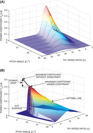
The wind turbine converts energy from the wind to the rotor shaft that rotates at a speed . The power of the wind depends on the wind speed V, the air density ρ, and the swept area , where R is the rotor radius. From the available power in the swept area, the power on the rotor is given based on the power coefficient (see Fig. 2A) which in turn depends on the pitch angle of the blades β and the tip-speed ratio :
|
|
(1) |
|
|
|
Figure 2. Power coefficients. This picture is reproduced from Stotsky and Egardt [2]. (A) Power coefficient as a function of the pitch angle of the blades β and the tip-speed ratio λ. (B) Power coefficient under constraint on the flapwise bending moment. The cut surface that represents the upper bound on the flapwise bending moment restricts the turbine power coefficient. The line that defines a maximum coefficient at each value of the pitch angle is plotted with the black plus signs and is referred as an optimal line.
|
The aerodynamic torque applied to the rotor is given as:
|
|
(2) |
Control-oriented modeling of the drivetrain
A drivetrain model consists of a low-speed shaft rotating with a speed and a high-speed shaft rotating with a speed , having inertias and , respectively. The shafts are interconnected by the gear with ratio N. A torsion stiffness together with a torsion damping result in a torsion angle α that describes the twist of the flexible shaft. This leads to the following drivetrain model:
|
|
(3) |
|
|
(4) |
|
|
(5) |
Models (3)-(5) can be reduced via multiplication of both sides of (4) by N and subsequent summation with (3), when assuming that the torsion rate is equal to zero [3][12]:
|
|
(6) |
where is a lumped rotational inertia of the system. A nomenclature and the parameters of the turbine model described above are presented in [2].
The turbine model (6) can be seen as the control-oriented and simplified model, which is suitable and recommended for the control design, whereas models (3)-(5) can be used for detailed simulations of the turbine response or for control design for drivetrain with essential flexibility of the drive shaft.
Pitch actuator model
The pitch actuator is modeled as a first-order lag with rate and range constraints:
|
|
(7) |
|
|
(8) |
where is the actuator control input, τ is a time constant, is a communication delay, and and are positive constants which define the range and rate constraints, respectively.
The steady-state blade operational loads
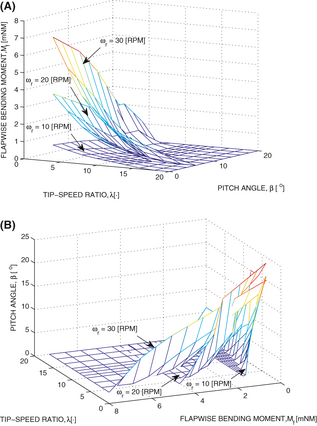
A mean value model of the flapwise and edgewise blade root bending moments can be presented in the form of look-up tables (the surfaces in three dimensional space) with the tip-speed ratio and blade pitch angle as input variables. Notice that the wind turbulence introduces fluctuations around the mean values of blade loads. The surfaces that describe the flapwise blade bending moment as a function of the tip-speed ratio and blade pitch angle for different turbine speeds are shown in Figure 3A. Each of those surfaces can be inverted so that the tip-speed ratio and flapwise bending moment are the input variables and the blade pitch angle is the output variable. Those inverse surfaces are plotted in Figure 3B and can be used for the determination of the desired pitch angle in the flapwise bending moment regulation.
|
|
|
Figure 3. Flapwise Bending Moment Modeling and Control. The picture is reproduced from Stotsky and Egardt [4]. (A) The flapwise bending moment as a function of tip-speed ratio and pitch angle. (B) Pitch angle as a function of the flapwise bending moment and tip-speed ratio.
|
Wind speed measurements in simulation model
The wind speed measurements can be used directly in the turbine simulations that allows modeling of realistic sample rates, noises and, other factors. Wind speed measurements with the sample rate of 1 Hz [3] are used in the turbine simulations in this article.
Problem statements
First, the control aims are divided in two parts with respect to control variables. The desired turbine speed is selected to optimize the turbine output, and desired blade pitch angle is chosen to satisfy the constraints on the flapwise and edgewise bending moments.
Second, the desired generator torque and pitch actuator input should be chosen in order to track the desired turbine speed , and blade pitch angle as follows:
|
|
(9) |
|
|
(10) |
The pitch control loop is assigned to satisfy the following constraints on the flapwise and edgewise blade bending moments:
|
|
(11) |
|
|
(12) |
and the speed control loop is designed for optimization of the turbine power.
The desired turbine speed can be chosen in two ways. The first one corresponds to the tip-speed ratio at the maximum power coefficient without constraints (11) and (12), and the tip-speed ratio of the second one corresponds to the maximum power coefficient with constraints (see Fig. 2B, [2]). These two approaches result in approximately the same desired turbine speed profile for slight constraints on the flapwise bending moment, but the latter requires a significant computational effort.
Look-Ahead Calculations
Preprocessing of the wind speed signal
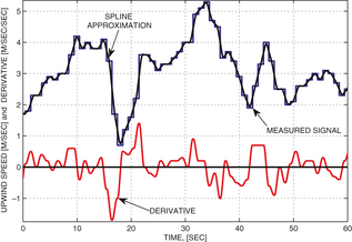
The wind speed signal measured at a distance in front of the turbine with a relatively low sampling rate (compared to other signals of the system) should be processed properly to achieve the desired high performance regulation. Preprocessing of the wind speed signal includes estimation of the derivative of the signal for further inclusion in the control system. Spline interpolation method can be used for estimation of the derivatives of noisy signals in preprocessing [3]. The measured upwind speed signal is approximated via a polynomial of a certain order as a function of time, and the derivatives are calculated analytically. Application of the spline interpolation method with a second order spline is illustrated in Figure 4, where a high-performance derivative signal is created from the upwind speed signal with a low sample rate.
|
|
|
Figure 4. Numerical differentiation of the upwind speed signal via spline interpolation method. The wind speed signal is measured with the frequency of 1 Hz and plotted with a blue line, where the constant offset of 5 [m/sec] is subtracted at each step. The second order polynomial (plotted with a black line) as a function of time is fitted to the measured signal in the least-squares sense in a window which is moving in time. The derivative (plotted with a red line) is calculated in the middle of this window. This picture is reproduced from Stotsky and Egardt [3].
|
Look-Ahead calculation of the blade loads: generation of the desired piecewise constant blade pitch angle profile
The future/predicted blade loads can be modeled using upwind speed measurements and static maps shown in Figure 3A. The desired pitch angle profile is calculated using the surfaces which are inverse to the flapwise bending moment surfaces. Those inverse surfaces are shown in Figure 3B with the desired flapwise bending moment and upwind speed as input variables. The desired pitch angle profile, calculated via the inverse surfaces, guarantees that the flapwise bending moment will not exceed the desired upper bound [2].
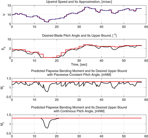
The time chart of look-ahead calculations is shown in Figure 5. All the calculations are driven by the upwind speed which is plotted in the first subplot with a blue line together with its spline approximation plotted with a red line. The desired pitch angle profile, which is calculated using the approach described above, is plotted with a black line in the second subplot. This profile guarantees that the flapwise bending moment does not exceed a prespecified upper bound as it is shown in the fourth subplot, where the bending moment is plotted with a black line and its upper bound is plotted with a red line.
|
|
|
Figure 5. The time chart of look-ahead calculations. The upwind speed is shown in the first subplot with a blue line together with its spline approximation plotted with a red line. The desired pitch angle profile and its upper bound are plotted with black and red lines, respectively, in the second subplot. The flapwise bending moment is plotted in the third and fourth subplots with a black line for continuous and piecewise constant pitch angle profiles, respectively. The desired flapwise bending moment is plotted with a red line. This picture is reproduced from Stotsky and Egardt [4].
|
Finally, Figure 3A shows that larger pitch angles imply lower flapwise bending moment at a fixed turbine speed. Therefore, overbounding of the desired pitch angle profile with a piecewise constant function of time guarantees that the flapwise bending moment does not exceed a prespecified upper bound. An upper bound of the desired pitch angle is plotted with a red line in the second subplot of Figure 5. The corresponding flapwise bending moment is plotted with a black line in the third subplot, and its upper bound is plotted with a red line.
The look-ahead calculations result in the desired piecewise constant blade pitch angle profile with available values in preview (future values) that allows the design of a new robust turbine load control system with improved performance, see section ‘Rapid proactive control of the blade pitch angle’.
Turbine Speed Control Strategies
Turbine speed control based on simplified model
The robust control strategy that uses the calculated ahead derivative of the wind speed signal and based on model (6) can be written as follows [3]:
|
|
(13) |
where the desired turbine speed ( is the tip-speed ratio at the maximum power coefficient) is driven by the wind speed V measured at the turbine site, and the derivative of the desired turbine speed depends on the upwind speed derivative , cleaned from the noise in the preprocessing (see section ‘Preprocessing of the wind speed signal’) and shifted according to the preview time, using frozen turbulence assumption. The turbine speed is calculated via generator speed , and the feedback gains and in (13) are positive.
Notice that the derivative of the desired turbine speed plays the role of the preview part in the control action (13) and significantly improves the performance of the regulation.
This strategy, when combining (6) with (13), results in the following closed-loop system:
|
|
(14) |
|
|
(15) |
where . This model represents a stable dynamics and the turbine speed converges to the desired speed with the guaranteed performance [3].
The Lyapunov function candidate , which has the following derivative along the solutions of (14) and (15) can be used for the proof of the system stability. Moreover, a constant offset due to the mismatch between the upwind and actual wind speed derivatives can be successfully compensated via the integral part of this controller.
Comparison and relation to the existing controller
Controller (13) can be compared to the following feedforward controller described in [1]:
|
|
(16) |
where is the maximum power coefficient achievable by the turbine, and is the tip-speed ratio at this maximum power coefficient.
The aerodynamic torque can be written as follows:
|
|
(17) |
Combination of (6) and (16), (17) results in the following closed-loop dynamics [1]:
|
|
Representation of two ratios and with a common denominator and subsequent Taylor series expansion of the power coefficient around the operating point gives the error model similar to (15) with and .
The closed-loop system with controller (16) shows a robust performance, but a relatively slow convergence. The convergence rate of the feedforward controller can be improved via introduction of feedback and preview loops [13][14]. Besides the controller (16) is not globally stable, compared to the algorithm (13) which is globally stable.
Driveline control based on integral backstepping
The drivetrain with a long low-speed shaft can be better described by two inertias interconnected by a spring and damper which model the twist of the flexible shaft. This drivetrain can be controlled via cascade control of the driveline torsion angle, estimated via the difference between the angles of rotation of low- and high-speed shafts. The rotational turbine and generator speeds are estimated via corresponding rotational angles. The control aim is to choose the generator torque so as to drive the rotor speed to the desired constant rotor speed .
Define the desired torsion angle , desired generator speed and generator torque as follows:
|
|
(18) |
|
|
(19) |
|
|
(20) |
where , and , are feedforward parts and , , , , , are positive gains.
The feedforward parts of the controller (18)-(20) are calculated when equating all the derivatives of the model equations (3)-(5) to zero:
|
|
(21) |
|
|
(22) |
|
|
(23) |
and resolving (21)-(23) with respect to the feedforward torsion angle , generator speed , and generator torque . Notice that the feedforward parts of the controllers (13) and (20) are the same and can be used as a simple feedforward driveline controller. The feedforward parts of (18)-(20) define the desired operating point, whereas the feedback parts minimize the deviations from this operating point. Simulation results show that this controller is a powerful tool for damping of the drivetrain oscillations [2].
Blade Pitch Control Strategies
Rapid proactive control of the blade pitch angle
The desired blade pitch angle profile, calculated using upwind speed measurements (see section ‘Look-Ahead calculation of the blade loads: generation of the desired piecewise constant blade pitch angle profile’), is a piecewise constant function of time with available values in preview (future values). This allows the design of a high-performance pitch regulation system with the highest possible transient rate, used in the algorithm as a parameter.
The transient between two constant desired values of the blade pitch angle is described as a linear function of time with the rate which corresponds to the maximum blade pitch rate . This linear function can be seen as a spline that describes the shortest feasible path between the two constant desired values. The desired trajectory in the transient between two constant values and , is defined as follows:
|
|
where the start time of transient together with the constant are calculated for the prescribed values of the rate limit and the stop time of transient , see Figure 6. Availability of the preview information in combination with the spline planning allows the advance start of the transient that occurs with the highest possible transient rate (used in algorithm as the parameter) at the prescribed stop time.
The transient control action for the blade pitch actuator, compensated for the delay time , is defined as follows [3]:
|
|
(24) |
which in combination with (7) results in the following exponentially stable closed-loop dynamics:
|
|
(25) |
Figure 6 shows the comparison of two responses of the blade pitch actuator with the control action (23) and the conventional control action for the piecewise constant without any preview information. The transient response of the system with algorithm (23) is essentially better than the response of the system with the conventional algorithm due to availability of the preview information, proactive planning, and control action.
|
|
|
Figure 6. The proactive transient between two desired pitch angles and , plotted with a red line. The transient response for the conventional algorithm is plotted with a blue line. The planned desired transient trajectory is plotted with a green line, with the transient start and stop times and , respectively. The response of the pitch actuator driven by control algorithm (23) is plotted with a black line. This picture is reproduced from Stotsky and Egardt [4].
|
Finally, the performance of the simultaneous speed and pitch control (13) and (23) is illustrated in Figure 7. The wind speed record is shown in the first subplot, the performances of the pitch and speed controls are shown in the second and third subplots, respectively, and finally the corresponding flapwise bending moment is shown in the fourth subplot.
|
|
|
Figure 7. The time chart of the wind speed (red line in the first subplot), the desired and actual pitch angles (red and black lines, respectively, in the second subplot), the desired and actual rotor speeds (red and black lines, respectively, in the third subplot), and the flapwise bending moment (black line in the fourth subplot) of the forward looking control strategy. This picture is reproduced from article [4].
|
Postprocessing Perspective: Estimation of the Inertia Moment
Postprocessing methods can be used as a powerful tool for the high performance estimation of the turbine parameters.
Indeed, inertia moment J can be estimated using measurements of the generator speed and turbine model (6), which can be written in the following form:
|
|
(26) |
where is the regressor and is unknown parameter.
As an example, the following prediction error-based estimator can be used:
|
|
(27) |
|
|
(28) |
|
|
(29) |
where θ is an estimate of , and ψ and ɛ are two auxiliary filters for estimation of the prediction error. Evaluation of the variable , where yields the following:
|
|
(30) |
and hence due to a proper choice of the initial values. Therefore, the variable can be used instead of the prediction error , and estimator (28) be written as follows:
|
|
(31) |
The regressor φ is bounded away from zero in the turbine transient operation. This in turn implies that ψ is also bounded away from zero, which guarantees the convergence of the estimated inertia to the true inertia moment.
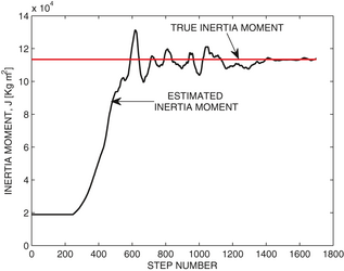
The high-gain estimator, described above, is sensitive to the generator speed measurement noise and its application in real time gives a noisy estimate of the inertia moment. High-quality estimation is achieved in the case of postprocessing only, after cleaning of the noisy generator speed measurements.
The performance of postprocessing estimation of the inertia moment is illustrated in Figure 8. Estimated inertia moment is used in the control strategies for improvement of the performance of the turbine speed regulation, and in monitoring functions for detection of the ice on the blades in cold climate.
|
|
|
Figure 8. Postprocessing estimation of the inertia moment. The estimated inertia moment is plotted with a black line and true inertia is plotted with a red line. This picture is reproduced from Stotsky and Egardt [4].
|
Conclusion
A significant cost reduction of the LIDAR systems is expected in the next coming years, which implies a potential availability of the wind speed preview information. This in turn opens new challenges in the field of turbine control, since the preview information might be used differently. This overview describes one of the ways to use this information for proactive turbine control. The problem is far from being solved, and the approach is sensitive to: (1) the wind speed measurement errors; (2) inaccuracies due to the frozen turbulence assumption; (3) uncertainties in load model; and (4) other factors. Despite these drawbacks, the approach remains promising. The benefits related to the inclusion of the preview information in the individual pitch control and yaw control should be further studied.
Acknowledgments
This study was supported by the Swedish Wind Power Technology Center (SWPTC). The authors are grateful to Magnus Ellsen for providing wind speed measurements from the Hönö wind turbine.
Conflicts of Interest
None declared.
References
- Pao, L., and K. Johnson. 2009. A tutorial on the dynamics and control of wind turbines and wind farms. Proc. of American Control Conference, 10–12 June, St. Louis, MO, USA, 2076–2089.
- Stotsky, A., and B. Egardt. 2012. Proactive control of wind turbine with blade load constraints. Proc. IMechE Part I: J. Syt. Control Eng.226: August 985–993.
- Stotsky, A., and B. Egardt. 2012. Model based control of wind turbines: look-ahead approach. Proc. IMechE Part I: Journal of Sytems and Control Engineering226:1029–1038.
- Stotsky, A., and B. Egardt. 2013. Robust proactive control of wind turbines with reduced blade pitch actuation, Proc. of the 5-th Symposium on System Structure and Control, Part of 2013 IFAC Joint Conference SSSC, Grenoble, France, 4–6 February, 2013, pp. 690–695.
- Biegel, B., M. Juelsgaard, M. Kraning, S. Boyd, and J. Stoustrup, 2011. Wind turbine pitch optimization, IEEE International Conference on Control Applications (CCA), Part of 2011 IEEE Multi-Conference on Systems and Control, Denver, CO, USA. 28–30 September, 2011, pp.1327–1334.
- Soltani, M., R. Wisniewski, P. Brath, and S. Boyd. 2011. Load reduction of wind turbines using receding horizon control, IEEE Conference on Control Applications (CCA), Part of 2011 IEEE Multi-Conference on Systems and Control, Denver, CO, USA. 28–30 September, 2011, pp. 852–857.
- Mirzaei, M., N. Poulsen, and H. Niemann. 2012. Robust model predictive control of a wind turbine, Proc. of American Control Conference, Fairmont Queen Elizabeth, Montreal, Canada, 27 June-29 June, 2012, pp. 4393–4398.
- Wang, N., K. Johnson, and A. Wright. 2012. FX-RLS-based feedforward control for LIDAR-enabled wind turbine load mitigation. IEEE Trans. Control Syst. Technol.20:1212–1222.
- Laks, J., L. Pao, A. Wright, N. Kelley, and B. Jonkman. 2011The use of preview wind measurements for blade pitch control. Mechatronics21:668–681.
- Simleyz, E., L. Pao, N. Kelley, B. Jonkman, and R. Frehlich. 2012. LIDAR wind speed measurements of evolving wind fields, The 50-th AIAA Aerospace Sciences Meeting including the New Horizons Forum and Aerospace Exposition, 9–12 January, Nashville, Tennessee, USA, AIAA 2012-0656, pp. 1–19.
- Bossanyi, E.2012. Un-Freezing the turbulence: improved wind field modelling for investigating Lidar-Assisted wind turbine control, Proc. of EWEA 2012, Copenhagen, Denmark, 16–19 April, 2012.
- Boukhezzar, B., and H. Siguerdidjane. 2005. Nonlinear control of variable speed wind turbines without wind speed measurement, Proceedings of the 44-th IEEE Conference on Decision and Control, and the European Control Conference, Seville, Spain, 12–15 December, 2005, pp. 3456–3461.
- Schlipf, D., S. Kapp, J. Anger, et. al. 2011. Prospects of optimization of energy production by LIDAR Assisted control of wind turbines, Proceedings of the EWEA Annual event, Brussels, Belgium, 14–17 March, 2011.
- Scholbrock, A.,P. Fleming, L. Fingersh, A. Wright, D. Schlipf, F. Haizmann, and F. Belen. 2013. Field testing LIDAR based feedforward controls on the NREL controls advanced research turbine, Preprint NREL/CP-5000-57339. January 2013.
Document information
Published on 01/06/17
Submitted on 01/06/17
Licence: Other
Share this document
Keywords
claim authorship
Are you one of the authors of this document?


