Abstract
This paper analyzes the partitioned and monolithic strategies to simulate tightly coupled hidroelastic problems. The seakeeping hydrodynamics solver used is based on a first-order linear time-domain FEM model with forward speed and double-body linearization. The structural dynamics solver is based on a full 3D time-domain FEM with corotational shell elements accounting for the geometric non-linearity. Both solvers are implemented under the same programming framework, which allows to implement the monolithic strategy, and to minimize the communication overheads of the partitioned strategy. Two case studies are used to test and compare the partitioned and monolithic coupling: a flexible catamaran in oblique waves, and a large floating reticulated structure made of fiber reinforced plastic. In both cases, the monolithic strategy is between three and four times faster than the partitioned strategy.
This project has been developed under the H2020 project FIBRESHIP aimed at developing the technology to design and build the structure of large-length vessels in fiber reinforced polymers.
This is a pre-print version of an article published in Marine Structures. The final version is available online at: https://doi.org/10.1016/j.marstruc.2021.103098
1. Introduction
Current rules and regulations cover adequately most of the aspects relevant to the structural ship design. However, several essential aspects are vaguely addressed, or rely upon a case-by-case approval process by the authorities. Among these aspects we can highlight different phenomena involving the hydroelastic response, such as springing, whipping and racking, resulting in dynamically induced hull stresses.
The above mentioned dynamic phenomena can increase significantly the hull stresses. Therefore, in some critical cases, the quasi-static approach to hydroelasticity used by the current rules and regulations can largely underestimate the actual design loads. Hence, in some cases, it is required to study the coupled hydroelastic response of the structure [1] by carrying out experimental tests at model scale and/or running computer analysis.
There are two different methods for hydroelastic model testing. The first one and least popular, due to its complexity and cost [2], is to build a model using some elastic material trying to scale down the elastic behavior of the ship [3,4]. In this method, the evaluation of the vibration modes cannot be estimated properly in fully elastic models due to larger internal damping [5]. The second one (and the most popular) is to build a segmented model connected by a flexible beam with similar global elastic properties [2,6,7,8,9,10,11]. The number of segments depend on the number of displacement modes to model. The pros and cons of both methodologies were analyzed and compared in [5], where the advantages of the second option are highlighted.
Anyhow, a major drawback of both testing techniques is than only global hydroelastic effects can be modelled and measured. The only alternative to analyze more local effects is the use of numerical simulations.
The numerical simulation of hydroelasticity involve the coupling between the hydrodynamics and the structural dynamics. The most common approach is to solve the hydrodynamics with 3D potential flow using the boundary element method (BEM), and the structural dynamics with the 1D beam model using the finite element method (FEM) [10,11,12,13,14,18]. Several works have extended the fluid dynamics model, by solving the Navier Stokes equations instead of the potential flow equations [15,16,17]. From the structural point of view, just a few authors have used more sophisticated approaches such as the 1D-3D FEM hybrid method [12,18] or directly coupling a fully 3D FEM [19]. Most of the works only consider the linear response, while the most common approach for modeling the structure is based on the superposition of modes [1,9,16,19], regardless the dimension of the model (1D beam or 3D).
In order to be able to simulate transient or non-linear responses, it is necessary to work in the time-domain [1]. In the context of potential flow solvers, Cummins [20] proposed the use of the impulse response function to transfer the results from the frequency-domain to the time-domain, and different authors have followed this approach [9, 10, 11, 18]. It requires to perform the structural modal analysis, and to solve the wave radiation problem for the corresponding displacement modes. A main drawback of this approximation is that it cannot accurately capture the local stresses -essential to predict failure- which mainly depend on local strains [21]. In order to overcome this drawback, it is necessary to solve in the time-domain the full 3D coupled hydroelastic problem.
Solving the full hydroelasticity problem in the time-domain is much less common in the literature due to its complexity and computational cost. In [22] a partitioned strategy was implemented to analyze the interaction between the free surface and the seals of a surface effect ship. The hydrodynamic model was based on potential flow with forward speed, and the results were compared with experimental tests. A recent work [14] solved the global hydroelastic response of a S175 ship using a coupled BEM–FEM approach and compared the results against the equivalent rigid body problem.
Very flexible floating structures with natural frequencies close to the wave frequency range are rare yet. An example could be two rigid bodies connected by some flexible structure (as the first case study that will be presented in this work). A reason might be the lack of tools to assess their design with affordable computational times.
In this work, a full time-domain hydroelastic model using a FEM-FEM coupled approach is presented. On the one hand, the hydrodynamics model is based on a first-order linear potential flow and takes into account the forward speed effect using the double body linearization. The velocity potential is solved using the FEM along with the SUPG for the free surface boundary condition [23,24,25]. On the other hand, the structural dynamics is solved using a co-rotational shell FEM model that takes into account the geometric non-linearity.
From the numerical point of view, two strategies can be adopted in this work to solve strongly coupled hydroelastic problems in the time domain. The first one is the partitioned coupling, where to different solvers are tightly coupled via the exchange of coupling variables in an iterative process. The second one is the monolithic coupling, where both models are implemented in a single code, allowing to formulate and solve the equations governing the flow and the structure dynamics with a single solver.
The partitioned coupling, also referred as iterative coupling, is the most common approach for coupled problems because it leverages existing investment in legacy codes development and permits those codes to continue to evolve independently [21]. This approach allows choosing the most effective solution for each solver, and makes easier the code development. However it requires a robust coupling algorithm that respect conservation laws, and an iterative algorithm that ensure convergence (which is not trivial). This coupling can be computationally expensive due to the iteration process required within each time step and the communication overheads.
Monolithic coupling has the advantage that the coupling occurs at the governing system level, avoiding an iterative process between solvers, which is the tightest scheme available. Since there is a single data structure that embodies discretization of the coupled system of fluid and structure, there is no communication overheads. However, the coupled system contains very different types of field variables, leading to a numerically ill-conditioned system of equations [21].
Both coupling strategies have been implemented and the objective of this work is to compare them in terms of robustness and computational efficiency. The paper is organized as follows. In Section 2, we present the statement of the seakeeping model. It is based on a time-domain wave diffraction-radiation solver based on the finite element method (FEM). In Section 3, we present the structural model, which is based on geometrical non-linear shell finite elements. In section 4, the two coupling strategies implemented are presented. In section 5 two application examples are shown: the first one is a flexible catamaran in oblique waves; and the second one is the analysis of large floating structure. Finally in Section 5, we discuss the different results and arrive at some conclusions.
2. Seakeeping model
The seakeeping model used in this work is a first-order linear time-domain wave diffraction-radiation solver based on the finite element method (FEM). Non-linearities, such as wet surface intermittency, quadratic velocity term in pressure equation, non-linear wave effects, or drag forces, are not considered. The seakeeping model was developed in-house and integrated in the commercial package SeaFEM [26]. The governing equations, respect to a global frame of reference located at the mean water level with OXY representing the horizontal plane, and OZ the upward vertical direction, are given by:
|
|
|
(1) | ||
|
|
|
(2) | ||
|
|
|
(3) | ||
|
|
|
(4) | ||
|
|
|
|||
|
|
|
(5) |
Where is the velocity potential ( ), is the free surface elevation, is the fluid domain, is the free surface pressure, represents the still water level, is the horizontal gradient operator, is the wetted Surface of a floating body, is the sea bottom Surface, is a normal vector to a Surface at point P, is the velocity of point p, is the initial vertical position of point P, and is the vertical displacement of P.
The solution can be split into the incident and diffracted-radiated wave components:
|
|
|
(6) | ||
|
|
|
(7) |
where and are the velocity potential and wave elevation respectively for the incident wave field, and and are the velocity potential and free surface elevation respectively for the diffracted-radiated waves respectively. The incident wave field is described by the Airy wave analytical solution. Introducing the separation of variables into the governing equations, the wave diffraction-radiation problem is obtained in terms of and as independent variables.
The free surface pressure is in a region close to the body (near field), but beyond the near field, , where is a factor that grows with the distance to the body. This term is used to dissipate the diffracted-radiated waves [23, 25]. Moreover. Details on the wave diffraction-radiation governing equations can be found in [22, 23, 24].
In this work the numerical solution using FEM of the above system reported in [22, 23, 24] will be used. It requires to solve the following system of equations:
|
|
(8) |
Where is the Laplacian Matrix, and the right hand side is obtained summing up the vectors , , and . The right hand side are obtained from discretizing the boundary conditions using FEM as in [23,24,25]. The above system can be written clustering the nodes lying on the body surface as:
|
|
(9) |
where contains the velocities of a point lying on the structure boundary. In the case of having forward speed, the free surface boundary condition is integrated using the FEM SUPG scheme with the double body lineariazation, and the numerical details can be found in [22, 23]. For the zero forward speed, a fourth order compact Padé scheme is used for the free surface, and the numerical details can be found in [22, 24].
3. Structural model
The structural dynamic model used in this work is based on geometrical non-linear shell finite elements. The geometrical non-linear model is based on the corotational method developed by Felippa and Haguen in [27]. The core element used by the corotational shell model is a 3-node element with three translations and three rotations per node, which is obtained by the combination of a membrane element and a plate element. The membrane element is based in the optimal triangle element with drilling rotation developed by Felippa in [28], while the plate element is based in the classical DKT element first introduced in [29]. This element has shown better performance that the standard bilinear quadrilateral element generally used in marine applications [28].
The algorithm used for the time-integration is based in the approximately energy conserving scheme presented by Almeida and Awruch in [30]. The complete model has been developed in-house and integrated within the commercial package RamSeries [31]. The governing equations of the model are given by:
|
|
|
(10) | ||
|
|
|
(11) | ||
|
|
|
(12) |
where is the stress tensor, is the mass force vector, is the structural domain, is the structural displacement vector field, is the part of the structural external surface with prescribed displacements , is the part of the structural external surface with prescribed tractions The numerical solution of the above system requires the numerical solution of the following system of equations:
|
|
(13) |
where is the current time step, is the tangent stiffness Matrix, is the incremental displacement vector of the nodes located in the interior, is the incremental displacement of the nodes in contact with the fluid, and is the right hand side which is obtained from the discretization of the boundary conditions using FEM [27,28,29]. The system above can be written clustering the nodes lying on the body surface as:
|
|
(14) |
Where contains the fluid pressure acting on the boundary condition.
4. Coupling strategies
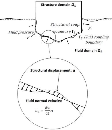
The purpose of this section is to present the two coupling strategies implemented to tightly couple the seakeeping hydrodynamics solver and the structural dynamics solver. The coupled problem is sketched in Figure 1.
As presented above, the seakeeping and structural problems will be discretized using the FEM. However, it is not required to use identical discretization for the common boundary where the interaction occurs will be discretized. Spatial linear interpolators have been used in this work to transfer the fluid pressure to the structure boundary and to transfer the structural displacements to the fluid boundary.
|
|
(15) | |
|
|
(16) |
Where , , and are the fluid pressure and structural displacements at the structural and fluid discretization over respectively, and and are the corresponding interpolation matrices.
|
| Figure 1: Fluid-Structure interaction concept. |
4.1 Partitioned coupling
As introduced above, in the partitioned coupling the different solvers are tightly coupled via the exchange of coupling variables in an iterative process. It has the advantage of solving the seakeeping and structural dynamics independently using the most efficient algorithms for each one. For instance, a deflated preconditioned iterative solver could be used for the seakeeping problem [24], while a direct solver could be used for the structural solver. The main drawbacks of the partitioned strategy are that it requires a robust iterative algorithm to guarantee the convergence of the solver within every time step and that the exchange of information between the two solvers might introduce large computational overheads.
The seakeeping and structural solvers used in this work have been developed under the same programming framework. The utilities of the OpenMP library [32] have been used to create two parallel threads to run each solver in parallel and exchange field variables between them at code level. This way, the communication overheads are minimized when compared with coupling two independent solvers.
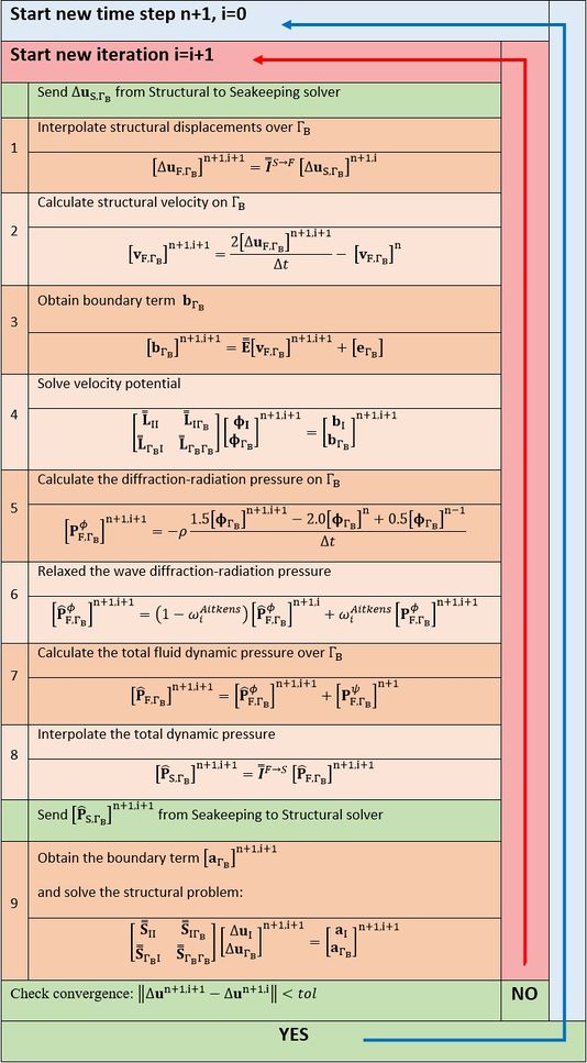
Figure 2 shows the iterative process implemented for the partitioned coupling. This process consist of 9 steps for every iteration. At first, it was observed that the direct exchange of fluid pressure and structural displacements had convergence issues. Hence, step 6 was introduced, using a constant relaxation factor for the pressure. While convergence can be achieved, it depends on the relaxation factor, which is not so obvious to estimate. Finally the Aitken´s method [22,33] was implemented and greatly improved the stability, and accelerated the convergence.
|
| Figure 2: Iterative scheme of partitioned coupling. |
4.2 Monolithic coupling
In the monolithic coupling, the fluid and structural governing equations are coupled through the common boundary condition. This leads to a coupled system of equations that contains the governing system of equations for the fluid and the structure, and a number of coupling equations that connect the independent variables through the shared boundary condition. As a result, the overall number of degrees of freedom is increased to take into account the effect of the fluid pressure on the structure, and the structural displacements on the fluid.
The procedure developed in this work to obtain the monolithic system of equations is presented below.
The fluid pressure can be decomposed as , where is the hydrostatic pressure, is the dynamic pressure induced by the incident wave field, and is the dynamic pressure induced by the diffracted and radiated waves. The only pressure component depending on the diffracted- radiated fluid velocity potential is and, therefore, is the responsible of the coupling. Hence, we can split the residual as and rewrite the equation (14) as:
|
|
(17) |
where n is the time step and i is the iteration step, contains the contribution of the hydrostatic and incident wave pressures. The subscript in indicates that the corresponding variable is evaluated with the variables in the structure side of the coupling boundary . Similarly, throughout this section, the subscripts and are used to indicate whether the corresponding variable is evaluated with the variables in the structure or fluid side of the coupling, respectively.
The diffraction-radiation component, , of the residual can be obtained as:
|
|
(18) |
The fluid pressure is obtained numerically from the velocity potential using Eq. (5), as:
|
|
(19) |
Using the interpolation matrix we obtain:
|
|
(20) |
Where and:
|
|
(21) |
Furthermore, the fluid body boundary condition term in eq. (9) comes from imposing that the fluid cannot penetrate the structure. That is to say, the displacement of a point lying on along the normal direction must match the one of the fluid particle at the same location. Hence, we can establish a relationship between the structural displacement and the fluid velocity at the boundary:
|
(22) |
where is the boundary velocity due to the structural displacement at point P. The boundary term can be expresses in matrix form as:
|
|
(23) |
Where is the vector containing the values of for those points , and is the assembled boundary condition matrix. The coupling term that relates the boundary velocity with the structural displacement can be expressed in matrix form as:
|
|
(24) |
Using the interpolation matrix we obtain:
|
|
(25) |
where . Assembling the equations above, the resulting global system of equations is:
|
(26) |
The monolithic coupling has the advantage of avoiding the iterative procedure required by the partitioned coupling, preventing iterative convergence issues. Instead, it requires to solve the system of equations given in Eq. (26) . Due to the very different field variables involved, this is an ill-conditioned system, requiring the use of a robust direct solver. In this work, we have used the shared-memory multiprocessing parallel direct sparse solver Intel-MKL’s PARDISO [34].
5. Application examples
5.1 Flexible catamaran in oblique waves
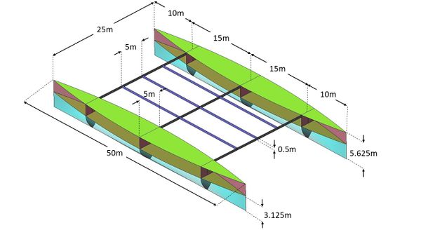
In this example, a flexible catamaran will be analyzed advancing in an oblique monochromatic wave. The catamaran consists of two Wigley hulls connected by flexible beams. Figure 3 shows the structural components as well as their layout and dimensions. Wave particulars are chosen to match the first torsional dry modal frequency. The main particulars of the ship, wave environment, and structural details are provided in Table 1.
| Waterline length | 50 m | |
| Distance between hulls | 25 m | |
| Draft | 3.125 m | |
| Wigley hull Breadth | 5 m | |
| Wigley hull Amidships section coefficient, Cm | 0.6667 | |
| Displacement [kg] | 698000 kg | |
| Steel density | 7844.67 kg/m3 | |
| Steel Young modulus | 210 GPa | |
| Steel plates thickness | Hulls | 0.04205 m |
| Decks | 0.04205 m | |
| Bulkheads | 0.04205 m | |
| Connecting Beams | 0.055 m | |
| Center of gravity | XG | 0 m |
| YG | 0 m | |
| ZG | 0.2195 m | |
| Radii of gyration | rxx | 12.45 m |
| ryy | 13.07 m | |
| rzz | 17.88 m | |
| Froude number | 0.215 | |
| Advancing velocity | 4.755 m/s | |
| Wave incident angle | 63.45 º | |
| Incident wave amplitudes | 0 m | |
| 0.01m | ||
| 0.1 m | ||
| 0.5 m | ||
| Incident wave period | 5.36 s | |
| Incident wave encountering period | 4.27 s | |
| Incident wave encountering frequency | 0.2342 Hz | |
| Water depth | 25 m | |
In this case study, a hydro-elastic analysis will be carried out using both, loose (one-way) and tight (two-ways) coupling formulations. For each formulation linear and non-linear geometry models for the structural analysis will be considered.
In order to carry out the loose coupling, first the seakeeping hydrodynamics simulation is carried out assuming the ship as a rigid body (uncoupled from the structural problem). Then, the dynamic pressure obtained will be used as a pressure load in the posteriori loosely coupled structural simulation.
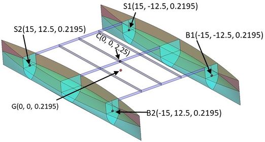
The global frame of reference is located at the center of the ship and on the mean water level. The ship is supposed to advance forward in the negative OX direction. But since the global frame of reference moves forward with the ship, the forward speed is modeled as a water current in the positive OX direction. For the rigid-body approximation, the center of gravity will be restricted to move in surge and sway, and rotate in yaw to avoid any drifting (modelling the effect of the propulsion and steering systems). In the structural simulations, the points B1 and S2 (see Figure 4) will be restricted to move in the forward OX direction, while points B2 and S1 will be restricted to move in the transversal OY direction. These restrictions are coherent with those used for the rigid body approximation.
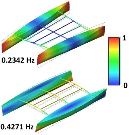
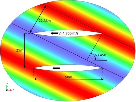
First of all, a structural modal analysis is carried out in dry. Figure 5 shows the main global structural modes with lower frequencies. It is observed that the first torsional mode happens at 0.2342 Hz. The incident wave length and direction, and the advancing velocity are adjusted to force this wave encountering frequency and to induce the torsional response. Figure 6 shows that the wave is selected to induce the torsion by a phase delay between the hulls pitch rotation. Then selecting an advancing velocity of 4.755 m/s the target wave encountering frequency is obtained.
Computational domain
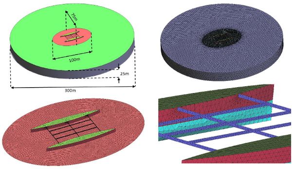
The computational domain consists of the near field and far field. The near field is an elliptical cylinder around the ship where mesh refinement is applied to solve accurately the wave diffraction-radiation problem. The far field goes from the near field to the edge of a circular cylinder of 300 meters in diameter. In this far field, diffracted and radiated waves are dissipated. Figure 7 shows the computational domain and mesh used. Table 2 reports the mesh sizes used in the near field free surface and the structural elements.
| Problem | Surface | Mesh type | Mesh size |
| Seakeeping | Free Surface | Unstructured | 1m |
| Wet Hulls | Unstructured | 1m | |
| Structural | Hulls | Unstructured | 1m |
| Bulkheads | Unstructured | 1m | |
| Decks | Unstructured | 1m | |
| Beams | Structured symmetric | 0.5mx0.166m |
| Structural
problem |
Number of nodes | 14306 |
| Number of degrees of freedom | 85836 | |
| Number of triangles | 28418 | |
| Seakeeping
problem |
Number of nodes | 43775 |
| Number of degrees of freedom | 43775 | |
| Number of tetrahedrons | 215056 | |
| Time step | 0.05s | |
| Number of time steps | 1000 | |
Dynamic analysis
In order to compare the dynamics of the ship considered as a rigid body or as an elastic structure, a number of dynamic parameters are defined based on the vertical displacement of five points. Figure 4 shows the location of those points, and Table 4 provides the definition of the dynamic parameters to be compared.
| Heave [m] | ||
| Pitch hull 1 [rad] | ||
| Pitch hull 2 [rad] | ||
| Pitch ship [rad] | ||
| Roll ship [rad] | ||
| Torsion [rad] | ||
| Transverse deflection [%] |
Dynamic analysis in the absence of incident waves
First the dynamic response of the ship in the absence of incident waves and with forward speed is analyzed. In this case, the ship is subject to the following structural loads: self weight, hydrostatic pressure, and dynamic pressure induced by the forward speed. Table 5 provides the results for different numerical approaches for the dynamic parameters.
| Coupling formulation | Structural model | [m] | [m] | [rad] | [rad] | [%] |
| Uncoupled | Rigid Body | |||||
| Loose | Linear | -0.047 | 0 | 0 | 0 | 1.271 |
| Non-Linear geometry | -0.047 | 0 | 0 | 0 | 1.028 | |
| Tight | Linear | -0.047 | 0 | 0 | 0 | 1.271 |
| Non-Linear geometry | -0.047 | 0 | 0 | 0 | 1.028 |
As expected, and are non-negligible values. It is known that the dynamic pressure of a ship advancing with forward speed induce a sinkage of the ship, which in this case is represented by . Moreover, at equilibrium, the hydrodynamic pressure and self-weight loads induce a transversal deflection represented by .
It is observed that this equilibrium deflection does not depend on the coupling strategy (tight or loose), since in equilibrium there are not hydrodynamic radiation loads. But it depends on the geometric model (linear or non-linear), showing a larger deflection for the linear one. This confirms the necessity of using a non-linear geometry model for sufficiently elastic structures like this catamaran.
If incident wave loads are considered, the larger the wave amplitudes, the larger the differences between the linear and non-linear geometry model will become. This is shown later in the dynamic analysis for different wave amplitudes.
Dynamic analysis with incident wave amplitude: Aw =0.5m
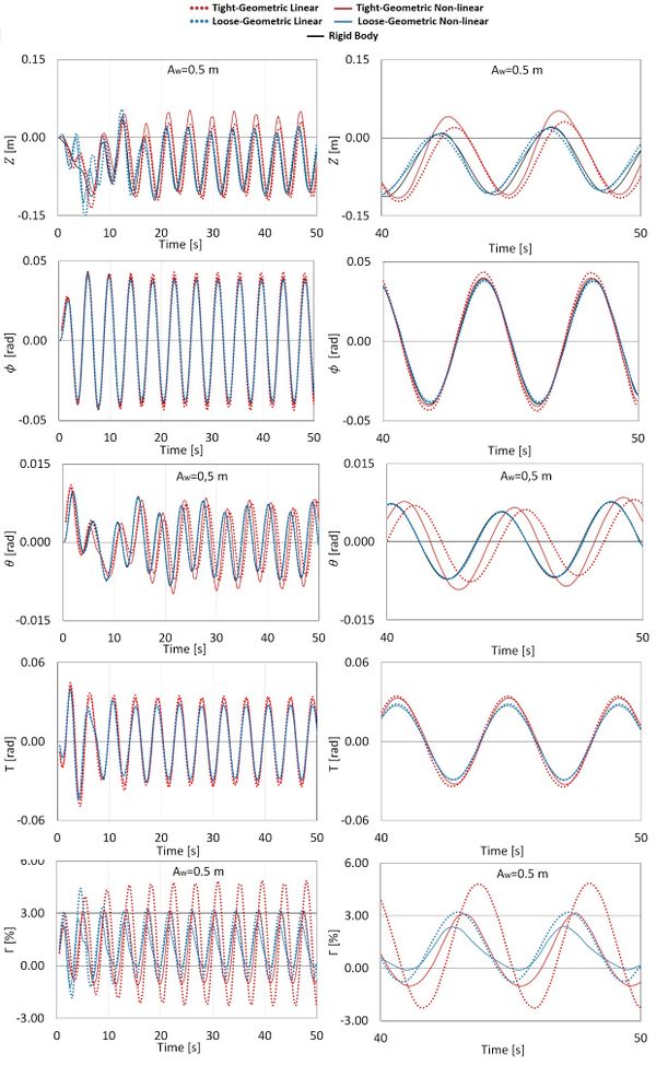
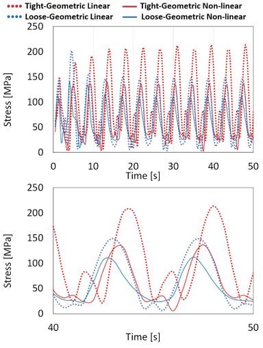
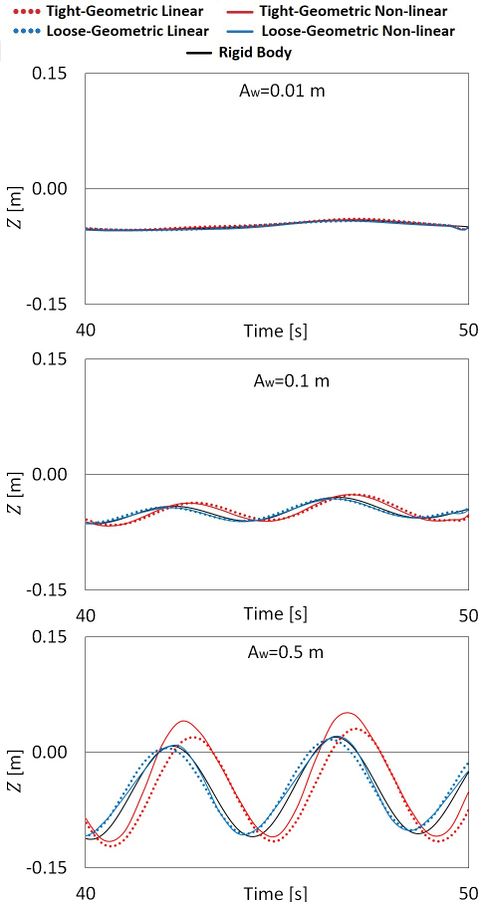
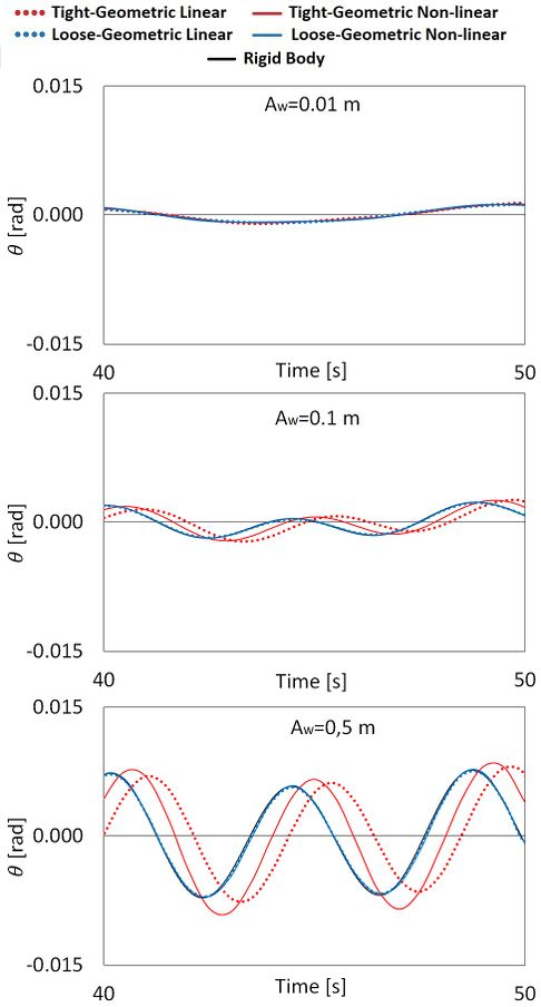
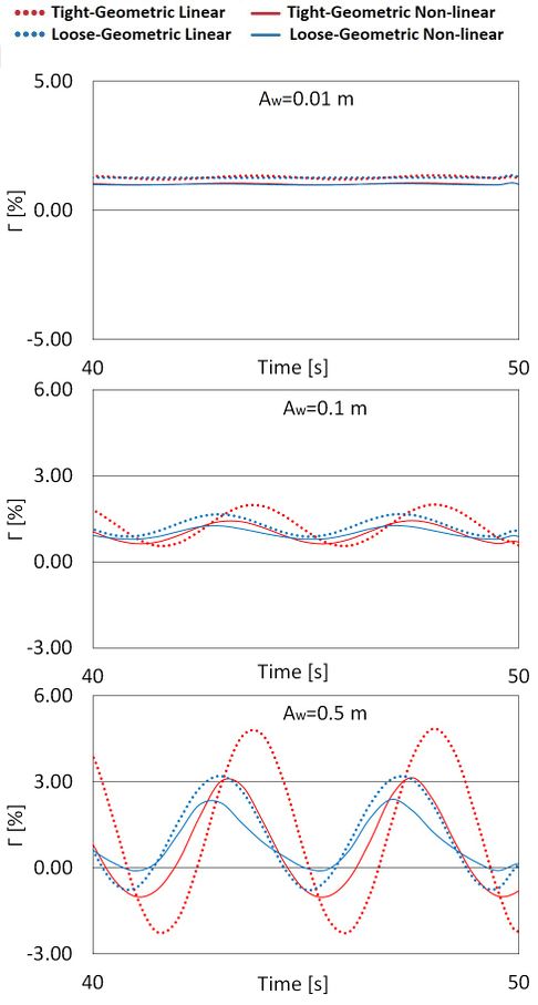
In this section, a dynamic analysis is carried including the incident wave load of a wave with 0.5 meter in amplitude. Figure 8 compares the dynamic parameters across the different numerical approaches, and Figure 9 compare the Von Misses stress at point C. Similar values are obtained by the monolithic and partitioned strategies, so only one is showed as tight coupling. The following conclusions are obtained:
- 1. Heave and Pitch motions: the loose coupling strategies provide very close results to the rigid body, while the tight coupling significantly differs. Moreover, in the tight coupling, significant differences are observed between the geometric linear and non-linear structural models.
- 2. Roll motion: all coupled strategies provide very similar results to the rigid body.
- 3. Torsional displacements: Significant differences are observed between the loose and tight strategies. However, no significant differences between using the geometric linear or non-linear structural models.
- 4. Transverse deflection: Significant differences are observed across the four coupling strategies.
- 5. There are large differences in the comparison of Von Misses stress measured at point C, located at the flexible beam structure.
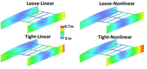
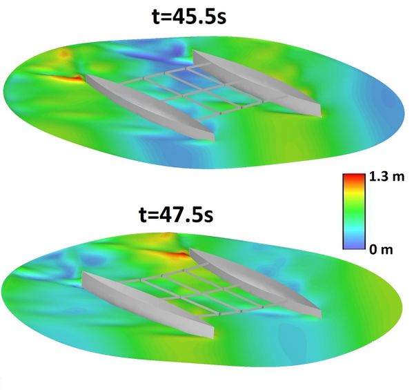
In this case study, it is observed that the elastic behavior of the beams connecting the twin hulls has a significant impact on the hydroelasticity of the ship. This impact makes the results obtained from the loose formulation to differ from those obtained with the tight formulation. Even though the heave, roll and pitch movements are small, the geometric non-linear structural behavior of the beams are also relevant for the global hydroelastic behavior of the ship. Figure 10 shows the differences of the instantaneous structural displacements at time=45s, and Figure 11 shows snapshots of the free surface elevation for the tight-nonlinear approach.
Looking at Figure 8, it is observed that the ship movements are small and therefore the use of a linear model is correct for the seakeeping hydrodynamics. On the other hand, a geometric non-linear corotational formulation has been chosen for the structural model, and there is a reason for that. Rigid body movements of a ship are expected to be dominant compared to structural displacements. And linear structural models are not capable of reproducing rigid body movements without inducing spurious structural strains (and stresses). These spurious stresses can be larger than the structural ones if the rigid body movements are large enough. On the other hand the corotational formulation is capable of reproducing non-small rigid-body movements without inducing spurious structural strains (and stresses).
Dynamic analysis for different incident wave amplitudes
The effect of the incident wave amplitude is also analyzed in this section. Figure 12, Figure 13, and Figure 14 compare the dynamic parameters , , and for three wave amplitudes: Aw=0.01m; Aw=0.1m; and Aw=0.5m. It is observed that, as the wave amplitude decreases, the differences between the different numerical approximations also decreases. For instance, m the differences in for Aw=0.5 are in the order of 2.5%, while for Aw=0.01m the differences are in the order of 0.2%. Actually the dynamic parameters for Aw=0.01m are very similar to those reported in Table 5 (equilibrium parameters in the absence of incident waves), where the transverse deflection in equilibrium are different for the geometric linear and non-linear models.
Figure 15 shows snapshots of the catamaran at the same time step for the monolithic coupling. Differences between the geometric linear and non-linear models are easily observed. It is difficult to understand why the geometric linear model provides larger transverse deflections due to the complexity of the problem, where bending and torsion are happening simultaneously. Hence the importance of developing numerical tools capable of simulating the hydro-structural dynamics.
Computational performance
In the partitioned coupling, the PARDISO direct solver is used for both, the hydrodynamics and structural parts. The fluid system of equations remains unchanged, requiring the solver to compute the approximate inversion of the structural system only once in the case of the tight-linear approach. However, the structural system has to be updated when using the geometric non-linearity, requiring to compute the approximate inversion of the structural system at every iteration. It is required only once for the linear approximation.
In the partitioned strategy, convergence is achieved when the maximum relative tolerance of the structural displacements is below 0.001. This tolerance value has been obtained from experience by ensuring that the monolithic and partitioned formulations provide similar results. A larger tolerance value will result in loss of convergence within the time steps and divergence of the solution over time.
In the monolithic coupling, the PARDISO direct solver is also used for the global system, requiring to compute the approximate inversion at every iteration for the non-linear geometry case, but only once for the linear.
This case study was run on a computer server with twenty four real CPU cores. Two OpenMP threads are used to run the seakeeping and structural problems, using twelve cores each of them. In the monolithic coupling, the global coupled system is assembled and solved within the seakeeping thread using the twenty four cores. Table 6 reports the CPU times for each approach.
Looking at Table 6 it is observed that the loose formulation is about 4 times faster than the tight formulation with the monolithic strategy, the use of the linear model is about ten times faster than the non-linear geometry, and the monolithic strategy is about four times faster than the partitioned one. It has to be taken into account that the number of structural degrees of freedom is about double the number of the hydrodynamic ones (see Table 3).
| Coupling formulation | Structural model | Solver strategy | Computational time (min) | Iterations/step | |
| Coupling | Structural | ||||
| Uncoupled | Rigid Body | - | 4 | - | - |
| Loose | Linear | 1-way | 10.2 | - | 1 |
| Non-Linear geometry | 1-way | 95.2 | - | 3 | |
| Tight | Linear | Partitioned | 175.2 | 7 | 1 |
| Monolithic | 42,1 | - | 1 | ||
| Non-Linear geometry | Partitioned | 1800 | 8 | 7 | |
| Monolithic | 420 | - | 9 | ||
5.2 Analysis of a large floating structure (LFS)
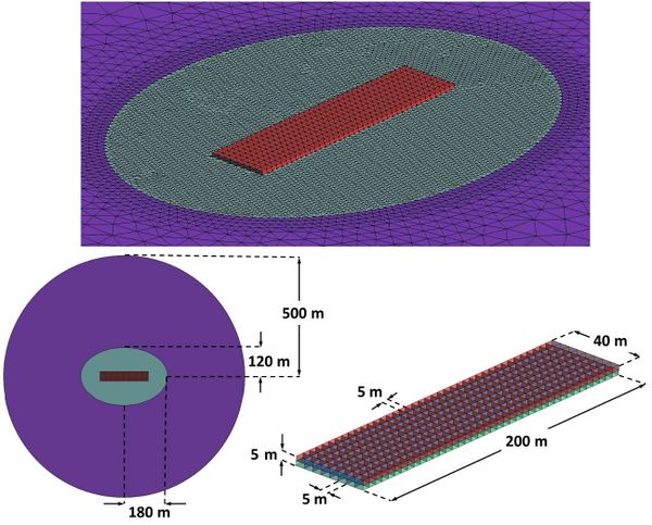
In this section the loose and tight coupling strategies will be compared when analyzing the elastic response of a LFS under an incident monochromatic wave. Figure 16 shows the main dimensions of the LFS as well as the spacing between longitudinal and transversal bulkheads, the dimensions of the computational domain, and the computational FEM mesh. The global system of reference is located at the geometric center point of the LFS, with the OX axis along the longitudinal direction, the OZ axis along the upwards vertical direction, and the mean water level at z=0.
The LFS is a reticulated structure made of fiber reinforced plastic (FRP). The points of the lines located at forward end (x=-100, z=0) and backward end (x=100, z=0) are restricted to move and rotate except for rotations around the OY axis (hinge constraints).
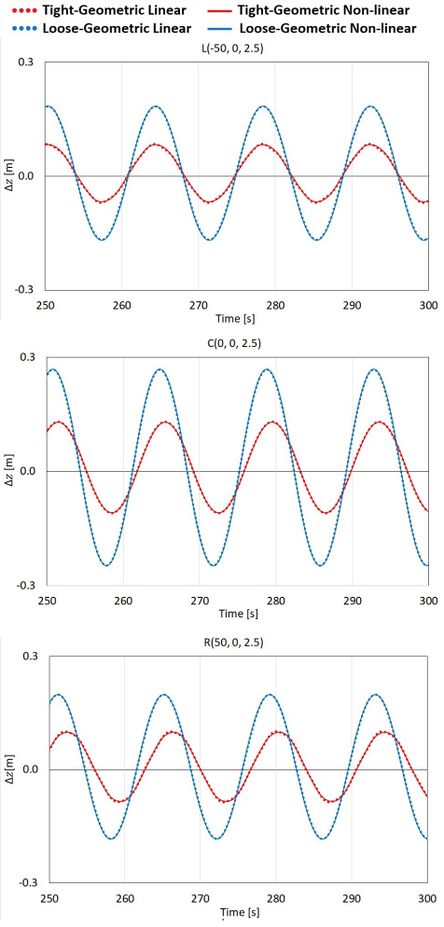
Table 1 provides the main particulars of the LFS and the incident wave, and Table 8 provides the details about the computational FEM mesh. The wave period is chosen to approximate the wave length to the length of the LFS in order to induce large bending moments. The vertical displacements will be collected at the following three points: L(-50,0,2.5), C(0,0,2.5) and R(50,0,2.5).
In this academic case study, the rigid body approximation implies that the LFS does not move due to the restrictions at the forward and backward ends. Then the dynamic pressure obtained will have no radiation component (only Froude-Krylov and diffraction). On the other hand, tight coupling approximation will take into account the radiation component due to the elastic displacements. In order to evaluate how significant the radiation is compared to the Froude-Krylov and diffraction components, the vertical displacement of three points will be compared. These displacements will be computed using the loose and tight coupling strategies.
| Length | 200 m |
| Breadth | 40 m |
| Draft | 2.5 m |
| LFS height | 5m |
| Displacement [kg] | 20500000 kg |
| FRP structural weight | 20500000 kg |
| FRP density | 2000 kg/m3 |
| FRP Young modulus | 21 GPa |
| FRP plates thickness | 0.249 m |
| Wave incident angle | 0 º |
| Wave period | 14 s |
| Wave amplitude | 0.5 m |
| Wave length | 200.4 m |
| Water depth | 25 m |
| Structural
problem |
Structural mesh size (triangle) | 5 m |
| Number of nodes | 1107 | |
| Number of degrees of freedom | 6642 | |
| Number of triangular elements | 4672 | |
| Seakeeping
problem |
Free surface nearfield mesh size (triangle) | 5 m |
| Fluid domain nearfield mesh size (tetrahedron) | 5 m | |
| Number of nodes | 44104 | |
| Number of degrees of freedom | 44104 | |
| Number of tetrahedral elements | 216151 | |
| Time step | 0.05 s | |
| Number of time steps | 6000 | |
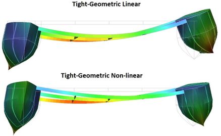
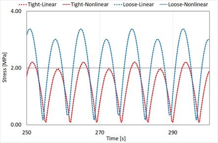
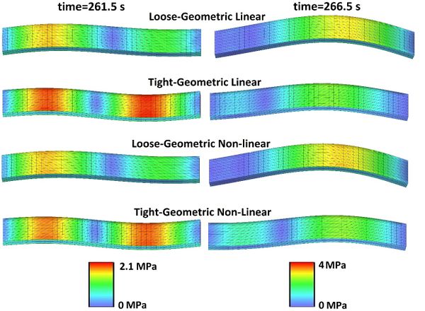
Figure 17 compares the vertical displacements at the L, C and R points for the four coupling strategies. Figure 18 compares the time history of the Von Misses stresses at point C, and Figure 19 compares snapshots of the structural displacements and stresses. Similar values are obtained by the monolithic and partitioned strategies, so only one is showed as tight coupling. We observe that the tight formulation reports significant lower displacements and stresses than the loose formulation. This confirms that the wave radiation component cannot be considered negligible respect to the Froude-Krylov and wave diffraction components. It is also observed that for this particular case, the linear and nonlinear structural approximations provide very similar results, which is expected considering the small beam deflection obtained.
This case study was run on a computer server with twenty four real CPU cores. Two OpenMP threads are used to run the seakeeping and structural problems, using twelve cores each of them. In the monolithic coupling, the global coupled system is assembled and solved within the seakeeping thread using twenty four cores. Table 9 reports the CPU times for each approach.
Looking at Table 9 it is observed that the monolithic strategy is about three times faster than the partitioned one. It has to be taken into account that the number of structural degrees of freedom is about seven times smaller than the hydrodynamic ones (see Table 8), and the impact of the structural on the computational time will be lower than in the catamaran case study.
| Coupling formulation | Structural model | Coupling strategy | Computational time (min) | Iterations/step | |
| Coupling | Structural | ||||
| - | Rigid Body | Uncoupled | 7.8 | - | - |
| Loose | Linear | One way | 93 | - | 1 |
| Non-Linear geometry | One way | 248 | - | 2 | |
| Tight | Linear | Partitioned | 338 | 11 | 1 |
| Monolithic | 104 | - | 1 | ||
| Non-Linear geometry | Partitioned | 2040 | 10 | 2 | |
| Monolithic | 644 | - | 4 | ||
6. Conclusions
In this work, a 3D tightly coupled hydroelastic model fully based on FEM has been presented. The seakeeping hydrodynamics solver can take into account the effect of forward speed using the double body linearization, and the structural solver can take into account geometric nonlinearities.
The hydroelastic problem is solved using loose and tight coupling formulations. And the latter is also solved using both, the partitioned and monolithic coupling strategies. The seakeeping and structural solvers have been developed under the same programming framework, which allows to reduce the communication overheads in the partitioned coupling, and also allows the implementation of the monolithic coupling.
Two case studies have been analyzed to test the performance of both coupling strategies. The first one analyzes the structural response of a 3D flexible catamaran under an oblique wave with forward speed. The second analyzes the 3D global structural response of a reticulated large floating structure made of fiber reinforced plastic. The monolithic strategy has been implemented successfully, showing no convergence issues when solving the monolithic global system of equations. The partitioned strategy requires to set a low enough tolerance value for the coupling scheme to ensure convergence within each time step, otherwise, the solution will diverge over time.
When analyzing the response of the catamaran, it is observed that the loose formulation do not approximate well enough the results obtained by the tight formulation in terms of displacements and stresses. And neither does the geometric linear model respect the non-linear geomtry model. With regards to the large floating platform case study, it is observed that the linear and non-linear geometry results are very similar but, again, the loose formulation does not approximate well enough the tight formulation. Besides, the loose formulation seems to overestimate the stresses on the structure. Then, the analysis of both cases requires of a tightly coupled scheme to take into account the wave radiation induced by the structural displacements.
Both case studies have been used to compare the computational times required by the different coupling approaches. For the catamaran case, the monolithic strategy is about 4- faster than the partitioned one. And 3 times faster for the large floating platform. This speed up seems to be larger as the ratio of structural degrees of freedoms to hydrodynamics degrees of freedom is larger. And although the monolithic requires to solve a much bigger system of equations, the reduction in the number of iterations lead to the overall reduction of the computational time.
Acknowledgements
The research leading to these results has received funding from the Spanish Ministry for Economy and Competitiveness under Grant RTI2018-094744-B-C21 (NICESHIP) and under the EU’s H2020 project FIBRESHIP (grant number 723360).
The authors are thankful to Jaume Sagués, and Ovidi Casals for the technical support provided to this research.
Compliance with ethical standards
On behalf of all authors, the corresponding author states that there is no conflict of interest.
References
[1] S. Malenica. Hydro structure interactions in seakeeping. International Workshop on Coupled Methods in Numerical Dynamics IUC, Dubrovnik, Croatia, September 19th-21st 2007.
[2] Maron, A., and Kapsenberg, G. (2014). Design of a ship model for hydro-elastic experiments in waves. Int. J. Nav. Archit. Ocean Eng. [6:1130~1147http://dx.doi.org/10.2478/IJNAOE-2013-0235 6:1130~1147http://dx.doi.org/10.2478/IJNAOE-2013-0235].
[3] Watanabe, I., Ueno, M. and Sawada, H., 1989. Effects of bow flare shape to the wave loads of a containership. Jorunal of the Society of Naval Architects of Japan, 166, pp.259-266.
[4] Hay, B., Bourne, J., Engle, A. and Rubel, R., 1994. Characteristics of hydrodynamic loads data for a naval combatant. Hydroelasticity in Marine Technology 1994, Trondheim, 22-28 May 1994, pp.169-188.
[5] Iijima, K., Hermundstad, O.A., Zhub, S. and Moan, T. (2009). Symmetric and antisymmetric vibrations of a hydroelastically scaled model. Hydroelasticity in Marine Technology 2009, Southampton, UK, 8-10 September 2009, pp.173-182.
[6] S. Mahérault, Q. Derbanne and F. Bigot (2013). Fatigue damage calculation of ULCS based on hydroelastic model for springing. Ships and Offshore Structures,
Vol. 8, Nos. 3–4, 289–302, http://dx.doi.org/10.1080/17445302.2012.750087.
[7] J-H. Kim, Y. Kim and A. Korobkin (2014). Comparison of fully coupled hydroelastic computation and segmented model test results for slamming and whipping loads. Int. J. Nav. Archit. Ocean Eng. 6:1064-1081.
[8] Y. Kim n, J-H. Kim (2016). Benchmark study on motions and loads of a 6750-TEU containership. Ocean Engineering119(2016)262–273.
[9] Z. Chen, H. Gui and P. Dong (2018). Nonlinear time-domain hydroelastic analysis for a container ship in regular and irregular head waves by the Rankine panel method. Ships and Offshore Structures, DOI: 10.1080/17445302.2018.1535243.
[10] J. Jiao, C. Chen, and H. Ren (2018). A comprehensive study on ship motion and load responses in short-crested irregular waves. International Journal of Naval Architecture and Ocean Engineering 11 (2019) 364e379.
[11] J. Jiao , Y. Jiang, H. Zhang, C. Li, and C. Chen (2019). Predictions of Ship Extreme Hydroelastic Load Responses in Harsh Irregular Waves and Hull Girder Ultimate Strength Assessment. Appl. Sci. 2019, 9, 240; doi:10.3390/app9020240
[12] Ki-Ho Shin, Jong-Woo Jo, Spyros E. Hirdaris, Seung-Gyu Jeong, Jun Bum Park, Frank Lin, Zhenhong Wang & Nigel White (2015) Two- and three-dimensional springing analysis of a 16,000 TEU container ship in regular waves, Ships and Offshore Structures, 10:5, 498-509.
[13] Kim, Y., Kim. J.H. and Kim, Y. (2015). Development of a highfidelity procedure for the numerical analysis of ship structural hydroelasticity. 7th International Conference on Hydroelasticity in Marine Technology, Split, Croatia, pp. 457-476.
[14] R. Datta and C. Guedes Soares (2019). Analysis of the hydroelastic effect on a container vessel using coupled BEM–FEM method in the time domain. Ships and Offshore Structures, DOI: 10.1080/17445302.2019.1625848.
[15] Oberhagemann, J., Shigunov, V., Radon, M., Mumm, H. and Won, S.I. (2015). Hydrodynamic load analysis and ultimate strength check of an 18000 TEU containership. 7th International Conference on Hydroelasticity in Marine Technology, Split, Croatia, pp. 591-606.
[16] Craig, M., Piro, D., Schambach, L, Mesa, J., Kring, D. and Maki, K. (2015). A comparison of fully coupled hydroelastic simulation methods to predict slam induced whipping. 7th International Conference on Hydroelasticity in Marine Technology, Split, Croatia, pp. 575-590.
[17] Lakshmynarayanana, P.A., Temarel, P., Chen, Z. (2015). Coupled fluid-structure interaction to model three dimensional dynamic behaviour of ship in waves. 7th International Conference on Hydroelasticity in Marine Technology, Split, Crotia, pp. 623-636.
[18] George Jagite, Xiang-Dong Xu, Xiao-Bo Chen & Šime Malenica (2018).
Hydroelastic analysis of global and local ship response using 1D–3D hybrid structural model. Ships and Offshore Structures, DOI: 10.1080/17445302.2018.1425521
[19] Im, H.I., Vladimir, N, Malenica, Š, Ryu, H.R. and Cho, D.S. (2015). Fatigue analysis of HHI SkyBenchTM 19000 TEU ultra large container ship with springing effect included. 7th International Conference on Hydroelasticity in Marine Technology, Split, Croatia, pp. 561-574.
[20] W.E. Cummins. The impulse response function and ship motions. Schiffstecknik,
[21] P. Hess (2016). Fluid Structure Interaction: A Community View . MSDL Report Number: 2016-003.
[22] J. Garcia-Espinosa, D. Di Capua, B. Servan-Camas, P-A. Ubach, Eu. Onatea (2015). A FEM fluid–structure interaction algorithm for analysis of the seal dynamics of a Surface-Effect Ship. Comput. Methods Appl. Mech. Engrg. 295, 290–304
[23] Servan-Camas B. 2016. A time-domian finite element method for seakeeping and wave resistance problems [doctoral thesis]. ETSI Navales, Universidad Politecnica de Madrid. http://oa.upm.es/39794/1/BORJA_SERVAN_CAMAS.pdf.
[24] J. Garcia-Espinosa and B. Servan-Camas (2018): A non-linear finite element method on unstructured meshes for added resistance in waves, Ships and Offshore Structures, DOI: 10.1080/17445302.2018.1483624.
[25] Serván-Camas, B. and García-Espinosa, J. (2013). Accelerated 3D multi-body seakeeping simulations using unstructured finite elements. J. Comput. Phys. 252,382–403.
[26] https://www.compassis.com/compass/es/Productos/SeaFEM
[27] Felippa C. (2005) and Haugen B., A unified formulation of small-strain corotational finite leements: I. Theory, Computer Methods in Applied Mechanics and Engineering 194, 2285–2335.
[28] Felippa C.A. (2003), A study of optimal membrane triangles with drilling freedoms, Computer Methods in Applied Mechanics and Engineering 192, 2125–2168.
[29] Dhatt, G. (1970), An efficient triangular shell element, AIAA.J., 8, 2100-2102.
[30] Almeida F.S. and Awruch A.M. (2011), Corotational nonlinear dynamic analysis of laminated composite shells, Finite Elements in Analysis and Design 47, 1131-1145.
[31] https://www.compassis.com/compass/es/Productos/RamSeries.
[33] Irons, B.M.,Tuck,R.C. (1969). A version of the Aitken accelerator for computer iteration. Int. J. Numer. Methods Eng. 1,275–277.
[34] https://software.intel.com/en-us/node/470282?language=ru
Document information
Published on 01/01/2021
DOI: 10.1016/j.marstruc.2021.103098
Licence: CC BY-NC-SA license
