1 Introduction
Severe convection weather such as hail has long been a potential risk to aircraft airworthiness. A short passing through hailstone regions is sufficient to cause damage to the aircraft fuselage, e.g. depression, cracking and even piercing [1]. The exposed parts such as nose, canopy, leading edge, radome and engine, will be easily damaged during this event, which severely affect both flight performance and mechanism operating [2]. Hail impacts can occur during flight and in ground events. Actually, ground hail also has the potential to damage aircrafts, as had occurred in Dallas, where grapefruit-sized hail was reported in 1995, damaging over 100 aircrafts on the ground [3]. Nonetheless, in-flight hail presents an even more severe threat than in-ground, due to the high velocity between aircraft and hail. Furthermore, bird strike is common and can be a significant hazard to aircraft safety. All forward facing components are concerned, i.e. the engine fan blades and inlet, the windshield, window frame, radome and forward fuselage skin as well as the leading edges of the wings and empennage. Loads of high intensity and short duration characterize a bird strike event. During impact, both the airplane structure (target) and the bird (projectile) undergo high inelastic strain rates and large deformations. Although the windshield, nose, wing/rotor and radome statistically are most at risk for a bird strike, engines sustained the highest percentage of actual damage among major components [4]. Several studies can be found addressing hail and bird impact testing in composite solutions [1, 5, 6]. Kim, et al. [7] performed an extensive experimental study of hail impact with velocities ranging from 30 to 200 m/s, focused on the impact response and resulting damage. Quasi-isotropic layups of AS4/977-3 and AS4/8552 carbon/epoxy woven prepreg were tested. These experiments showed a linear relationship between the measured peak force and the projectile kinetic energy, notwithstanding the projectile size. In addition, a linear relationship between the kinetic energy at which failure initiates, referred to as the failure threshold energy (FTE), and the thickness of the panel was found. Impacts at kinetic energies greater than the FTE produced a multiplicity of damage modes that were clearly described. Composite materials are increasingly being used to manufacture aircraft structures. Actually, the most revolutionary in the use of composites on commercial liners are the Airbus A350XWB and the Boeing 787, which contains 50% composite structure by weight and 90% by volume. In comparison, the Boeing 777, which entered service in 1995, contains only 10% of composite structures by weight [8]. Nevertheless, current solutions of several fuselage sections, namely, cockpit nose and canopy are still manufactured with aluminium.
This study evaluates the energy absorption of several composite solutions to replace the aluminium fuselage panels. It is included in the “PASSARO” project in the scope of the work package “WP3 – Development of Medium and High Energy Impact Protection Materials, Manufacturing and Qualification”. Advanced materials’ solutions to be integrated in the primary structure or as add-ons will be explored and developed for cockpit protection against medium and high energy impacts due to events such as stones, bird and hail impact. For this purpose, several coupons were manufactured in an autoclave and tested with metal and hail spheres, using compressed air cannon. The main concern was to achieve similar areal density to the existing solution. Phased array and radiography non-destructive inspections (NDIs) were performed to accesses damage.
2 Materials and methods
Carbon fibres are the predominant high strength and modulus reinforcement used in the fabrication of high-performance polymer-matrix composites. Carbon fibres typically contain more than 90 weight percentage of carbon and have remarkable properties. They include high tensile strength (up to 7 GPa), good compressive strength (up to 3 GPa), high tensile modulus (200 up to 900 GPa), low density (1.75 up to 2.18 g/cm3), good temperature resistance, low thermal expansion, good electrical and thermal conductivity, and chemical resistance [9]. Aramid fibres, e.g. Kevlar® due to their good mechanical properties such as high strength to mass ratio and modulus are extensively used in industrial, aerospace and military applications. It also shows very good properties at high temperatures for a polymeric material [10]. Despite Kevlar® possesses significantly low fibre elongation, it is well known for its enhanced impact properties. Ultra-high-molecular-weight polyethylene (UHMWPE) fibres are one of the strongest and lightest fibres available. Chemical inertness, impact and abrasion resistance can be appointed as the most remarkable properties. Dyneema® and Spectra® are two known brands of this fibre. However, UHMWPE fibres have thermal limitation that is inherent to polyethylene. Actually, the melting point of polyethylene fibres is around 134 °C. Therefore, these fibres are not suitable for extended tensile load at 90-100 °C. Yet, several methods may improve this performance such as physical or chemical cross-linking, surface modifications and fibre hybridization [11, 12]. The densities of the commercialized UHMWPE fibres are 0.97 g/cm3, which is two-thirds of the aramid fibres and half of high modulus (HM) carbon fibres [11]. Glass fibres are the most common of all reinforcing fibres for polymeric matrix composites. Advantages include low cost, high tensile strength, high chemical resistance and excellent insulation properties. On the other hand, the drawbacks include relative low tensile modulus and fatigue resistance, and high density among the commercial fibres. Actually, the two types of glass fibre usually used in the fibre reinforced (FR) plastics industry are E-glass and S-glass. E-glass is the cheapest of all commercially available reinforcing fibres, thus its application in industry is widespread. S-glass was originally developed for aircraft components. The compositional difference and higher manufacturing cost make it more expensive than E-glass [13].
The aforementioned materials were identified as the most promising ones to cope with the impact scenarios. Additionally, the solutions built with these materials are required to be multi-functional in terms of thermal and sound insulation, lightning strike protection and fire, smoke and toxicity issues, moisture absorption and corrosion. Several technologies were selected to build the coupons for impact testing. Hybrid composites are made of two or more different types of high strength fibre cushioned with a relatively low strength matrix to meet specific strength requirements. They offers the designer capabilities to obtain the required properties in a controlled considerable extent by the choice of fibres and matrix. However, the design of materials and structures becomes a key challenge on how to benefit from these fibres to produce a structure strong enough to endure different loads. The review of fibre hybridization in polymer composites performed by Swolfs, et al. [14] presents an overview of how impact performance is affected by the positioning of the layers in symmetric layups, namely the low elongation fibres (LEF). Through asymmetric interlayer hybrids of carbon and glass fibres, it becomes possible to test the glass side as well as the carbon side on the same layup. If the carbon layers are on the impacted side, the penetration impact resistance was increased by 30%. Similar tests on asymmetric aramid/carbon hybrids showed a higher penetration impact resistance if the carbon was on the impact side.
Fibre metal laminates (FMLs) are materials consisting of alternated layers of metal sheets (e.g. aluminium, magnesium, titanium alloys) and fibre-reinforced composites. FMLs presents new or improved properties, compared to traditional composites. The combination of two metal components and a fibre-reinforced polymer matrix composite as a hybrid composite leads to achieve a material of: high strength, great stiffness and strength to density ratio, flame and corrosive resistance, high fatigue and dynamic load resistance, good damping and insulation properties [15].
Recently, nano-filled matrixes have attracted significant interest due to their low price, high performance, excellent physicochemical and mechanical properties [16]. On the one hand, carbon nanotubes (CNTs) ultra-high strength along with their relatively low density and multifunctionality makes them an excellent candidate for aerospace structure applications. Actually, CNTs are very stiff, with a measured Young's modulus of 1.4 TPa, an expected elongation to failure of 20-30%, which combined with the stiffness, projects to a tensile strength well above 100 GPa. Moreover, theoretically CNTs has the ability to carry 109 A/cm2 which compared to copper wires, the electric-current-carrying capacity is 1000 times higher [17]. On the other hand, the worldwide interest in graphene is still increasing, as can be realized from the massive investment in research. The reason for this is mainly due to the multifunctionality of this 2D atomic crystal. Graphene combines unique properties such as: high thermal conductivity in the order of 5000 W/mK, high modulus of elasticity (±1 TPa) as well as tensile strength (130 GPa) and good electrical conductivity [18]. The most widely used graphene-related materials are graphene nano platelets (GnPs), which can be produced by exfoliating graphite, and graphene oxide (GO), of which production involves oxidation and exfoliation [19]. Pathak, et al. [20] investigate the mechanical properties effect of GO used as one of the filler for the development of CF/GO-epoxy hybrid composites. The outcomes show an increase of the bending strength by 66% and young modulus by 70% with only 0.3 wt% of GO. This increase is due to the improvement in properties of epoxy resin and interfacial interaction between reinforcement and matrix by hydrogen bonding. The graphene oxide utilization is one of the approaches for improving the properties of carbon fibre reinforced polymers (CFRP).
2.1 Coupons manufacture
All solutions were manufactured in a clean room designed and built for classification 10K, ISO 7. Coupons were manufactured with 300 x 300 mm and labelled with a unique code for further identification. Table 1 presents the number of layers, areal density and thickness of the evaluated solutions for the cockpit. For benchmark proposes the baseline solution for nose and canopy panels was considered to be made of a single aluminium 2024-T3 alloy sheet with 1.2 mm thickness. Kaiser Aluminum (US) supplied the aluminium alloy. The mechanical properties reported by the manufacturer include an ultimate strength of 467 MPa, yield strength of 310 MPa and elongation from 17.2 to 17.8 %. This set was commonly label as BSL1. An additional baseline was proposed aiming to provide a comparison basis with the developed enhanced solutions. This baseline commonly labelled as BSL3, includes 14 layers of UD T700 12 K carbon fibres, supplied by Toray and impregnated by SHD Composites (UK) with the MTC801 epoxy resin (40% RW).
Four solutions were manufactured, encompassing the hybridization of few fibres, namely, carbon, Dyneema®, Kevlar® and E-glass in an interlayer configuration. The first set hybridizes intermediate and high modulus UD carbon fibres, the T700 and M55J (6K), respectively. Both were supplied by Toray and impregnated by SHD Composites (UK), using the MTC 801 epoxy resin (40% RW). This set was commonly labelled as IHC1. Another set combine E-glass (G290T) and Kevlar® fabrics and UD T700. Saati (Italy) supplied the Kevlar® 29 fabric with 460 g/cm2. Moreover, SHD Composites supplied the E-glass with 280 g/cm2. This set was labelled as IHC2. The third configuration is similar to the previous, with the removal of the E-glass and was commonly labelled as IHC3. Finally, Dyneema® SK65 fabrics were staked between UD T700 carbon fibres. DSM supplied the Dyneema with 160 g/cm2. This set was commonly labelled as IHC4.
The following solutions are in the scope of the fibre metal laminate (FML) technology. Coupons incorporate aluminium 2024 T-3 sheets with 0.3 mm, UD T700 carbon fibres, and fabrics of Kevlar® 29, Dyneema® SK65 and E-glass. Kaiser Aluminum (US) supplied the aluminium 2024-T3 alloy sheet with 0.3 mm thickness. The mechanical properties reported by the manufacturer include an ultimate strength of 424 MPa, yield strength of 300 MPa and elongation of 16%. Aiming to improve metal-foam adhesion, a chemical surface treatment was applied to the aluminium surface in accordance with ASTM D3933 - Standard Guide for Preparation of Aluminum Surfaces for Structural Adhesives Bonding (Phosphoric Acid Anodizing). For this, coupons were subjected to a 9-12 wt% phosphoric acid (H3PO4) solution anodization followed by a rinse stage and coated with EW-5000 AS corrosion inhibiting structural adhesive primer (3M, USA). One design includes two layers of aluminium, UD T700 carbon fibres and FG, labelled as ML1. Another design was built with Dyneema® fabric stacked between two aluminium layers. This set was labelled as ML3.
Two solutions framed in the nano-filled matrixes (NFM) technology, manufactured with UD T700 carbon fibres are presented. One solution uses the MTC801 (40% RW) epoxy resin, previously doped at INEGI with multiwall carbon nanotubes (MWCNTs). Different loadings of pristine MWCNTs were prepared using a three-roll mill, EXAKT 80® from EXAKT Technologies, Inc., at a constant roll speed of 200 rpm.
After fibre impregnation in SHD facilities, three coupons were produced. This set was labelled as NFM1. On the other hand, the other solution uses the MTC9800 – graphene enhanced epoxy resin provided by SHD. Similar to the previous coupons, it was produced with UD T700 carbon fibres (40% RW). Three coupons were manufactured and labelled as NFM2.
| Coupons ID | Description | Nb. Layers | Areal density (kg/m2) | Thickness (mm) |
| BSL1 | Al 2024 T3 1.2 mm | 1 | 3.34 | 1.20 |
| BSL3 | T700 CFRP | 14 | 3.33 | 2.40 |
| IHC1 | M55J+T700 CFRP | 13 | 3.05 | 2.11 |
| IHC2 | T700+E-glass+Kevlar+E-glass+T700 | 8 | 3.36 | 2.29 |
| IHC3 | Kevlar+T700+Kevlar | 9 | 3.06 | 2.16 |
| IHC4 | Dyneema+T700+Dyneema | 14 | 3.31 | 2.76 |
| ML1 | Al 0.3+E-glass+T700+E-glass+Al 0.3 | 7 | 3.24 | 1.54 |
| ML3 | Al 0.3+Dyneema+Al 0.3 | 9 | 3.34 | 2.24 |
| NFM1 | T700 + epoxy doped with CNT | 14 | 3.28 | 2.40 |
| NFM2 | T700 + epoxy doped with Graphene | 14 | 3.39 | 2.44 |
3 Experimental impact tests
The campaign has been planned to evaluate the impact resistance of each solution, in the scope of the PASSARO requirements. For tests with metal spheres (mass of 7 and 28.2 g), the impact energies range between 35 and 320 Joule. In addition, for the hail spheres (mass of 38 and 68 g), impact energies range from 113 up to 1360 Joule. Whenever was possible the setup was design to obtain coupons with and without perforation, thus, several modifications were implemented during the campaign since the tests data was becoming available.
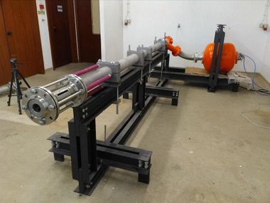
The cannon used for the impact tests is a single action compressed air device operating at a maximum pressure of 10 bar. The barrel has a smooth bore with 108 mm diameter configurable to 3 or 4 meter length. Driving power is supplied from a 150 litre pressure tank connected to the barrel by a large diameter fast response valve. A sabot that seals the barrel, and allows the air pressure to be applied, drives the projectile.
As sabot debris can produce unwanted impacts on the target panels as well as interfere with the speed measuring system, the muzzle is fitted with a spring loaded sabot catcher, which effectively reduces the bore to about 90 mm and maximum projectile diameter to approximately 75 mm. Since the exit speed depends on the payload mass (projectile plus sabot), so far, for payloads up to about 200 g, speeds between 100 and 250 m/s have been achieved at 5 bar (about half of full pressure). Figure 1 depicts the air cannon used to perform the impact test campaign.
3.1 Impactors
According with the project specifications steel and hail spheres were used to test and evaluate the solutions impact resistance capabilities. Table 2 presents the geometric characteristics of the different projectiles used.
| Material | Diameter [mm] | Weight [g] |
| Steel | 12.00 | 7.05 |
| 19.05 | 28.20 | |
| Ice | 44 | 37 |
| 52 | 63 |
The steel spheres were supplied by Luis Aparicio, SL (Spain), a steel bearing manufacturer. Thus, presenting very high size and weight precision. The spheres are manufactured in chrome steel AISI 52100 with a yield strength of 2034 Mpa. Hail spheres where produced using a two-step procedure.
1. Water is slowly freeze in order to produce a small ice slab free from air bubbles and internal cluttering with an appropriate dimension, suitable for the particular ice sphere being produced.
2. The slab is placed in an aluminium mould with the required diameter to produce the final sphere.
In both metal or hail impact tests, the spheres were driven out of the cannon barrel by a sabot which sealed the barrel and allow the full pressure to be used to accelerate the projectile. The sabots were hollow cylinders of EPS closed by EPS cylinders glued to both ends. A hole with the diameter of the projectile being fired was drilled on the frontal EPS disc, using a thermal pen, to lodge the projectile.
3.2 Target holder
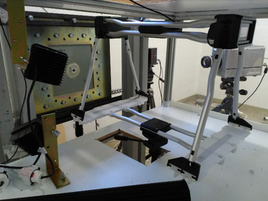
The test panels were firmly gripped between two steel frames (with an aperture of 240 x 240 mm) that were hold together by sixteen steel bolts as depicted in Figure 2. The frames are then tighten with eight bolts to a steel structure, which holds the target panel perpendicular to the projectile trajectory. All bolts are tighten with a torque of 12 Nm. In front of the target holding structure is placed a box intended to protect the cameras and speed measuring instrumentation from debris and the cannon air blast, as well as stopping re-bouncing projectiles from flying across the facility and eventually causing damage or personal injuries.
3.3 Speed measurement and video recording
The impact velocity was measured with a Caldwell G2 ballistic chronograph, shown in Figure 2, consisting of two light curtains placed in the projectile trajectory just before the target. The exit speed is measured by a Photron AX200 high speed camera mounted behind the target and perpendicular to the projectile trajectory. The camera was set to record 20K frames/s with a definition of 512x320 pixel and a shutter speed of 1/90000 s. An additional camera was placed in the front side of the target to record the impact. This was a Photron SA5 camera set to record 30K frames/s with the same 512x320 pixel definition and a shutter speed of 1/93000 s. In the cases where the projectile did not perforate the target and re-bounces this camera was also used to estimate the residual velocity.
For high-speed video recording, the lightening conditions are crucial and up to seven LED projectors were used to illuminate both sides of the target. Due the angle of the camera two projectors suffice for the rear face of the target panels whereas up to five placed at different angles could be required for the impact face.
3.4 Non-Destructive Inspection
NDIs were performed using a phased array ultrasound scan or radiography (X-Ray) depending on the material to be tested. The ultrasonic test is performed using an automatic inspection system composed by the immersion tank where the samples are placed and the inspection device (phased array probe) consists of a robot arm with six degrees of freedom.
In addition, few inspections were performed with a RollerForm device from OLYMPUS due to curvature shape presented in the coupons IHC3-1 and IHC3-2. The OMNISCAN MX2 was used for data acquisition.
X-Ray was used for all coupons with aluminium due to the sound attenuation caused by the aluminium layers. X-ray technique with 8 kV and 2 mA was used. In this test, the inspected area of the coupon is 240x100 mm (centred with the coupon), provided by a radiographic film with a D4 sensitivity.
Overall, radiographic films provide high-resolution images and are particularly appropriate for identifying internal discontinuities. Since the aluminium layers are quite thin, from 0.3 to 1.6 mm, the X-Ray technique was only able to detect superficial cracks.
4 Results
Figure 3 compares the longitudinal bending stiffness computed using the Classical Laminate Theory [21], thickness and areal density, of all solutions considered for the cockpit panels, normalised with the Aluminium 2024 T3 1.2 mm (BSL1). Regarding the bending stiffness, comparing all solutions with the BSL1, it is notorious that the ML3 behaves best with an increase of 420%. Moreover, deviations of 340% and 310% were found for the NFM1 and IHC1, respectively. The T700 (BSL3) presents an increase of 220%, and the lowest relative deviation was 60%, found for IHC3.
On the subject of areal density, the higher deviations from the BSL1 were -10% for IHC1 and IHC3. The NFM2 presents an increase of 2%, and for the remaining solutions, relative deviations below 1.5%. These low differences unveil the main idea to keep the same areal density as the BSL1, to allow an almost direct comparison of results. Therefore, the thickness was neglect in this first study. Generally, the solutions have approximately twice the BSL1 thickness, with the exception of the ML1 presenting a deviation of -30%. As would be expected, there is a dependency between the thickness and the bending stiffness of the coupons.
4.1 Impacts with Metal Spheres
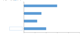
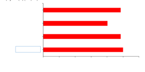
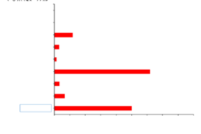
Figure 4 (a) qualitatively shows the absorbed energy for the tests performed with the 7 g metal sphere, normalised with the BSL1-3. All coupons were perforated when submitted to impacts at 150 m/s (79 J). The best performing solution was the ML3-2 absorbing more 110% of the impact energy than the BSL1. Furthermore, the ML1-2 behaves poorly absorbing -10%. The interlaminar hybrid solutions were tested with metal sphere in a late stage of the impact test campaign, since their performance with hail impacts was below our expectations. The IHC4-3 was the best performing among the interlaminar hybrid solutions absorbing more 75%. The IHC2-3, IHC3-3 and BSL3-4 presented better energy absorption by 50, 40 and 5%, respectively.
(a)
(b)
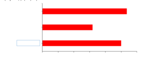
The comparison of the absorbed energy with the 28 g metal sphere at 150 m/s (320 J) is depicted in Figure 4 (b). The ML3-1 was the best performing solution, absorbing more 50% than the BSL1-8. On the other hand, the ML1-1 and BSL 3-6 presented worst behaviour by -20 and -40%, respectively.
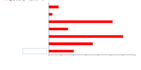
The damaged area of the solutions with aluminium (BSL1 and FML) was measured with digital image analysis, as for the FR ones, the delamination area was evaluated through the phased array technique. Figure 5 shows the damaged area of the coupons with 7 g (a) and 28 g metal sphere (b), comparing with the baseline (BSL1-3). The ML1-2 presented the lowest damaged area with -90%, followed by the ML3-2 and IHC3-3 with -60 and -20%. As for the BSL1-3, IHC4-3 and IHC2-3, presented higher damaged area compared with BSL1 by 80, 160 and 200%, respectively.
Observing Figure 5 (b), both ML1-1 and ML3-1 achieved lower damage than the BSL1 by 65%. Oppositely, the BSL3-6 showed additional 6% of damage. Comparing the damage area of the best performing FR and FML solutions with the 28 g sphere, the latter presented lower damage by 225%. Thus, the aluminium layers benefit the coupons damage absorption mechanisms.
(a)
(b)
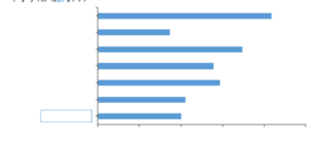
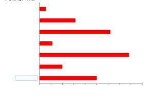
Figure 6 (a) depicts the absorbed energy per unit mass of the projected area of the 7 g metal sphere at 150 m/s (79 J), for perforated coupons. The ML3-2 coupon, with 110% better than BSL1-3, shows the best absorption capability. Furthermore, the hybrid composite IHC 4-3 with 70% follows, and the IHC2-3 and IHC3-3 performance stands out (average by 40%) from the BSL1. The ML1-2 despite it presented the lowest damage area, attained the worst performance for energy absorption per unit mass with -10% than the BSL 1.
(a)
(b)
Figure 6 (b) shows the absorbed energy per unit mass of the projected area of the 28 g metal sphere at 150 m/s (320 J), for perforated coupons. The ML3-1 absorption capability emerge from the others and is higher than the BSL1-8 by 35%. In addition, compared with the BSL1-8 the ML1-1 and BSL3-6 performance was lower by 25 and 40%, respectively.
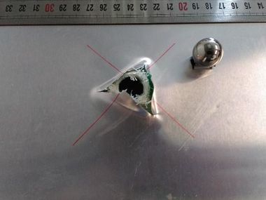
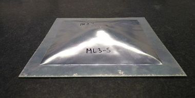
Figure 7 presents the rear face of the ML3-1 coupon. Perforation occurred with a small dishing deformation, followed by a petal damage pattern, with seven visible cracks on the front and three cracks on the back aluminium sheets. Crater diameter of 15.91 mm and normal distance of petal deformation of 20.02 mm.
4.2 Impacts with Hail Spheres
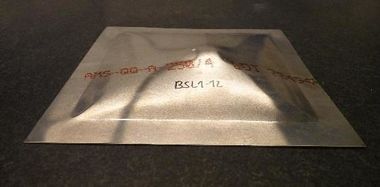
The evaluated solutions were all capable to endure the impacts energies for both 37 and 63 g hail spheres at 150 m/s. Since these outputs does not provide a comparison basis, the damaged area (permanent plastic deformation or delamination) evaluation follows. Figure 8 shows the BSL1 coupon after impact test with 63 g hail sphere. The failure mode is characterized by bulging and dishing. Normal distance of plastic deformation of 28.19 mm. Since the phased array technology is not capable to penetrate the aluminium sheets, and the X-ray tests does not provide the fibres damage, the normal distance of rear permanent deformation of the FML solutions was evaluated.
Figure 9 (a) depicts the coupons rear plastic deformation for the 37 g hail sphere.
(a)
(b)
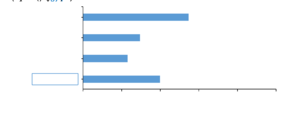
Comparing with the BSL1-10, the ML1-4 solution attained the lower rear plastic deformation (-20%). The ML3-4 and BSL1-11 deformations were very similar (3%). Similar behaviour was found for the damage caused by the 7 g metal sphere at 150 m/s in terms of damage ranking of the best performing solutions. In addition, all coupons become deformed in their completely free area (dishing), making the boundary of the target holder completely visible. Figure 9 (b) depicts the damage induced by the 63 g hail sphere (710 J). The ML1-5 presented the best performance in terms of rear permanent plastic deformation, with 35% lower than the BSL1-12. Contrarily, the ML3-5 showed an additional 10%. Nevertheless, coupons built with aluminium become completely deformed in their entire free area as depicted in Figure 10.
Figure 11 (a) presents the damage of the FR solutions assessed through phased array US inspection for 37 g hail spheres at 150 m/s (415 J). NDI test with the IHC4-1 coupon was inconclusive due to poor signal acquisition, therefore, the visual damaged area is presented instead. The nano-filled matrixes with CNTs (NFM1) and with graphene (NFM2) presented the best behaviour – zero damaged area as depicted in Figure 12 (a). Moreover, the hybrid solutions IHC2-1, IHC3-1 and IHC4-1 showed a lower damage by 95, 90, and 75%, respectively. In addition, the BSL3-7 and 8 attained damage lower by 85 and 95%, respectively. The IHC1-1 presented the worst performance, with a damaged area 25% above the BSL1-10.
Figure 11 (b) presents the damage induced by the 63 g hail spheres at 150 m/s. The NDI tests with the IHC1-2 and IHC4-2 coupons were inconclusive due to poor signal acquisition, therefore, the visual damaged area is presented. The NFM2-3 was the best performing solution with a damage area lower by 90%. By visual inspection, this solution was the only one presenting no damage. The hybrid IHC3-2 presented damage lower by 75% and the BSL3-9 follows with -60%. The NFM1 solution showed a lower damaged area about 40%. The IHC1-2 and IHC4-2 were severely damaged.
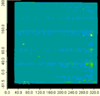
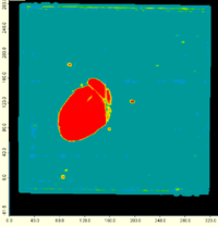
Figure 12 shows the C-scan results for nano-filled matrixes coupons tested with: (a) 37 g and (b) 63 g hail spheres. Both coupons presented zero visible defects.
(a)
(b)
- (1) (b)
5 Conclusions
The technologies studied for the nose and canopy panels were designed to have the same areal density (within 8%) as the baseline solution: aluminium 2024 T3 with 1.2 mm. Therefore, the thickness of the studied solutions is around the double of aluminium. In addition, improvements over 200% were found for the longitudinal bending stiffness. For metal sphere impacts, the ML3 solution with Aluminium + Dyneema® + Aluminium, presented the best energy absorption performance. Moreover, when compared with the baseline, the ML3 longitudinal bending stiffness was improved (≈420%), the areal density is similar, and the thickness is ≈85% higher. On the subject of the hail sphere impacts, the nano-filled matrixes with CNTs (NFM1) and with graphene (NFM2), presented the best behaviour with the 37 g hail spheres. In fact, both solutions had no delamination. Regarding the 63 g spheres, all solutions presented damage, but the nano-filled matrix with graphene (NFM2), was the best performing solution with a damage of 7% (of the coupon area). In addition, by visual inspection no damage was detected. Compared with the baseline (BSL1) the longitudinal bending stiffness was improved by ≈240%, the areal density is similar, but the thickness is slightly the double.
Acknowledgements
The authors gratefully acknowledge the collaboration with Juan Tomás Viana Lozoya in the scope of PASSARO, a CleanSky 2 Core Partnership led by Airbus Defence and Space. This project has received funding from the Clean Sky 2 Joint Undertaking under the European Union’s Horizon 2020 research and innovation program under grant agreement No 807083.
In addition, authors gratefully acknowledge the funding of Project POCI-01-0247-FEDER-017751 – ALIR_mcs, cofinanced by Programa Operacional Competitividade e Internacionalização (Compete 2020), through Fundo Europeu de Desenvolvimento Regional (FEDER).
References
[1] S. Li, F. Jin, W. Zhang, and X. Meng, "Research of hail impact on aircraft wheel door with lattice hybrid structure," in Journal of Physics: Conference Series, 744, no. 1, p. 012102: IOP Publishing, (2016).
[2] R. K. Souter and J. B. Emerson, "Summary of available hail literature and the effect of hail on aircraft in flight," NATIONAL AERONAUTICS AND SPACE ADMINISTRATION WASHINGTON DC, (1952).
[3] M. Saul and J. Lunford, "Damage from hail grounds nearly 100 D/FW planes passengers scramble as scores of flights cancelled," Dallas Morning News, May. 1, p. 1A.(1995).
[4] J. R. Allan, "The costs of bird strikes and bird strike prevention," Human conflicts with wildlife: economic considerations, p. 18.(2000).
[5] M. Mahinfalah and R. A. Skordahl, "The effects of hail damage on the fatigue strength of a graphite/epoxy composite laminate," Composite Structures. 42, no. 2, pp. 101-106.(1998).
[6] M. Guida, F. Marulo, M. Meo, and M. Riccio, "Analysis of Bird Impact on a Composite Tailplane Leading Edge," Applied Composite Materials, journal article. 15, no. 4, pp. 241-257.(2008).
[7] H. Kim, D. A. Welch, and K. T. Kedward, "Experimental investigation of high velocity ice impacts on woven carbon/epoxy composite panels," Composites Part A: Applied Science and Manufacturing. 34, no. 1, pp. 25-41.(2003).
[8] D. R. Tenney, J. G. Davis Jr, R. B. Pipes, and N. Johnston, "NASA composite materials development: lessons learned and future challenges."(2009).
[9] S. Chand, "Review Carbon fibers for composites," Journal of Materials Science, journal article. 35, no. 6, pp. 1303-1313.(2000).
[10] T. J. Singh and S. Samanta, "Characterization of Kevlar Fiber and Its Composites: A Review," Materials Today: Proceedings. 2, no. 4, pp. 1381-1387.(2015).
[11] X. S. Yi, S. Du, and L. Zhang, Composite Materials Engineering, Volume 1: Fundamentals of Composite Materials. Springer Singapore, (2017).
[12] X. Chen, Advanced Fibrous Composite Materials for Ballistic Protection. Elsevier Science, (2016).
[13] T. Sathishkumar, S. Satheeshkumar, and J. Naveen, "Glass fiber-reinforced polymer composites – a review," Journal of Reinforced Plastics and Composites. 33, no. 13, pp. 1258-1275.(2014).
[14] Y. Swolfs, L. Gorbatikh, and I. Verpoest, "Fibre hybridisation in polymer composites: A review," Composites Part A: Applied Science and Manufacturing. 67, no. Supplement C, pp. 181-200.(2014).
[15] V. K. Thakur, M. K. Thakur, and A. Pappu, Hybrid Polymer Composite Materials: Properties and Characterisation. Elsevier Science, (2017).
[16] K. R. Reddy, C. Venkata Reddy, B. Babu, K. Ravindranadh, S. Naveen, and A. V. Raghu, "Chapter 8 - Recent advances in layered clays–intercalated polymer nanohybrids: Synthesis strategies, properties, and their applications," in Modified Clay and Zeolite Nanocomposite Materials, M. Mercurio, B. Sarkar, and A. Langella, Eds.: Elsevier, pp. 197-218, (2019).
[17] Berber M.R. and H. I.H., Carbon Nanotubes - Current progress of their polymer composites. Croatia: IN TECH, (2016).
[18] D. G. Papageorgiou, I. A. Kinloch, and R. J. Young, "Mechanical properties of graphene and graphene-based nanocomposites," Progress in Materials Science. 90, pp. 75-127.(2017).
[19] P. Hung, K. Lau, B. Fox, N. Hameed, J. H. Lee, and D. Hui, "Surface modification of carbon fibre using graphene–related materials for multifunctional composites," Composites Part B: Engineering.(2017).
[20] A. K. Pathak, M. Borah, A. Gupta, T. Yokozeki, and S. R. Dhakate, "Improved mechanical properties of carbon fiber/graphene oxide-epoxy hybrid composites," Composites Science and Technology. 135, no. Supplement C, pp. 28-38.(2016).
[21] A. C. Ugural, Stresses in beams, plates, and shells. CRC press, (2009).
Document information
Published on 01/06/22
Accepted on 28/05/22
Submitted on 28/05/22
Volume 04 - Comunicaciones Matcomp19 (2020), Issue Núm. 1 - Avances en Materiales Compuestos. Nuevos Campos de Aplicación., 2022
DOI: 10.23967/r.matcomp.2022.06.019
Licence: Other
Share this document
Keywords
claim authorship
Are you one of the authors of this document?
