Abstract
In the present study, friction welding is carried out to weld two dissimilar materials of SA 213 tube to SA 387 tube plate using an external tungsten carbide tool to enhance and validate the mechanical and metallurgical properties. The two optimizing techniques are Taguchi L9 orthogonal array and ANOVA method for obtaining the optimal joint strength from process parameter respectively and for obtaining the maximum welding joint strength with output parameter of compressive strength. Then it is followed by the micro structural studies to reveal about the welding configuration which is capable of producing defect-free welds. In addition, hardness and compression strength of welds were obtained with nine different work pieces with various conditions. The two kinds of materials are taken in this investigation, where type 1 is tube without hole and type 2 is tube with hole on its circumference. It was observed that the optimal joint strength for the work piece without hole and with hole is 2980 MPa and 2680 MPa, respectively. The value of Vickers hardness test was found in the welded zone to be much greater in work piece without hole that the work piece with hole is 292 Hv and 217 Hv, respectively.
Keywords
FWTPET; Backing block; Taguchi method; ANOVA; Micro structure; Micro hardness
1. Introduction
The friction welding is a vital solid-state joining process and it possesses high popularity in welding of non-weld alloys. It is a metal fabrication process that has a high potential for application in industrial area such as power plants, manufacturing, automobile, electronics, aerospace. Friction welding of tube to tube plate is a new solid joining technology invented in the year 2006 [1] and it has many benefits when compared to other types of welding process example such as fusion welding. Friction welding produces weld under the pressure of compressive forces. Some of the advantages of friction welding include the ability to weld non-weld able alloys and produce good quality weld joints [2]. One of the important characters of FWTPET is that its capability to produce high quality leak proof joints [3]. When compared with traditional tube to tube plate welding techniques, it is an energy efficient environmental eco friendly and versatile process [4], [5], [6] and [7]. Senthil Kumaran et al. state that the use of backing block in the FWTPET process leads to defect free weld joints and better strength [8]. This process of identification of suitable combination of input parameters so as to produce the desired output parameters necessitates several experiments to be conducted which is a time-consuming task and consumes significant amount of cost. Several efforts have been taken to understand the effect of process parameters on material flow behaviour, micro structural formation and mechanical properties of friction welded joints [9]. The steel tube is welded with aluminium tube plate with support of backing block using FWTPET process and the bonding interface microstructure and mechanical properties of steel tube with and without projection [10] and friction welding of aluminium tube to tube plate has been performed and the process parameters have been prioritized using Taguchi L9 orthogonal array [11]. In the study, the frictional welding of SA 213 tube to SA387 tube plate with support of backing block using an external tungsten carbide tool is carried out in vertical milling machine. On this research, tube is prepared with two different conditions such as without hole [WOH] and with hole [WH]. In this process, the tube is taken as SA 213 and the tube plate is SA 387 for both types. In total, eighteen work pieces were assembled with normal fit between them and welding is carried out with using backing block. The both type 1 and type 2 have nine welded work pieces each for these present investigations. In this FWTPET process, the three levels of process parameters have been used in this study. The process parameters such as tool rotational speed, depth of cut and tube projection were considered to obtain the optimal joint strength. Taguchi statistical deign is a powerful technique which is used to identify the most significant process parameter by the conduct of relative fewer experiments [12]. Taguchi L9 orthogonal array has been used to identify the moist influential process parameter. Analysis of variance (ANOVA) is used to obtain the total percentage of contribution of each parameter. The comparison of both conditions was conducted through four techniques such as percentage of contribution for each significant parameters, the regression analysis, the micro structural study about the heat affect and welded zone in the work piece which differs from base metal of the work piece and micro hardness test to calculate the hardness value of welded work piece at various zones.
2. Experimental details
2.1. Material selection
2.1.1. Tool material and design
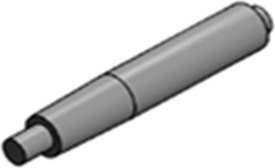
In this study, the friction welding of tube to tube plate is carried out with the external tool which is made up of Tungsten carbide, and this tool has a mechanical property of more hardness than the work piece used in this investigation. The diameter of this tool was 27 mm and 170 mm in length. In the beginning, the facing operation is made to make the surface of the tool level and then turning is done to eliminate the material to obtain the desired tool shape. Fig. 1 shows the titanium tool used in this research work and Table 1 shows the chemical composition of the external tool.
|
|
|
Figure 1. Titanium carbide – external tool. |
| Tungsten carbide | Element | C | H | Fe | O | Ni | Mo | Ti | V | Pd |
|---|---|---|---|---|---|---|---|---|---|---|
| weight% | 0.08 | 0.015 | 0.25 | 0.13 | 0.75 | 4.31 | 0.4 | 4.5 | 0.20 |
2.1.2. Work piece material and design
The friction welding is carried out for the work piece tube is made of SA 213 and SA 387 for tube plate. Table 2 and Table 3 show the chemical composition of the tube SA 213 and tub plate SA 387 respectively.
| SA 213 | Element | Mn | Cr | Mo | Ni | Cop | Ti | Fe |
|---|---|---|---|---|---|---|---|---|
| weight% | 0.51 | 1.46 | 0.42 | 0.046 | 0.044 | 0.090 | 97.1 |
| SA 387 | Element | Mn | Cr | Mo | Va | Ti | Fe |
|---|---|---|---|---|---|---|---|
| weight% | 0.75 | 1.55 | 0.38 | 0.041 | 0.087 | 96.7 |
2.1.2.1. Type 1: tube without holes
In type 1 conditions, the tube plate is considered as SA 387 and tube is taken as SA 213 having no holes on its circumference and Fig. 2 shows the tube and tube plate without hole [WOH].
|
|
|
Figure 2. Tube without hole. |
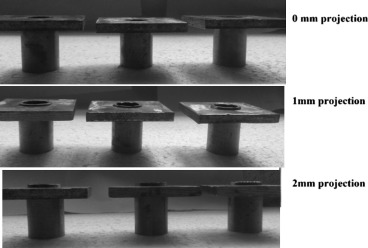
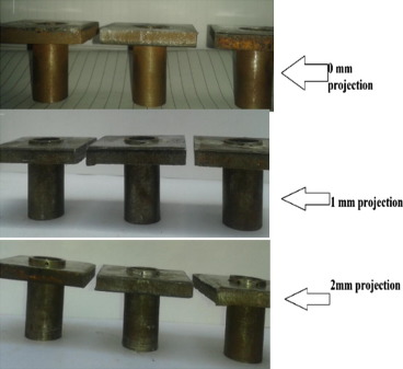
In total, nine pieces of tube and tube plate assembly were considered and the assembly of the work piece is done provided with the normal fit between them and the projection of tube is given value of 0 mm, 1 mm and 2 mm for three set of pieces. Fig. 3 shows the three sets of work piece and with their projection before welding process.
|
|
|
Figure 3. Assembly of work piece without hole and with their projection. |
2.1.2.2. Type 2: tube with holes
In type 2 conditions, the tube plate is taken as SA 387 and tube is taken as SA 213 having holes of diameter 2 mm on its circumference and Fig. 4 shows the tube with hole [WH]. In total, nine pieces of tube with hole and tube plate assembly were considered and the assembly of the work piece is done provided with the normal fit between them and the projection of tube is given value of 0 mm, 1 mm and 2 mm for three set of pieces. Fig. 5 shows the three sets of work piece and with their projection before welding process.
|
|
|
Figure 4. Tube with hole [WH]. |
|
|
|
Figure 5. Assembly of work piece without hole and with their projection. |
2.1.3. Backing block design
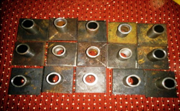
The backing block is a fixture made of cast iron to support the work piece which is clammed in the milling machine during the experiment. The small gap is provided for the clearance fit between the backing block and the assembled work piece tube and tube plate. This aspect has been ensured by means of proper selection of dimensions of the tube as well as the hole. This backing block is made up of cast iron of size about 50 mm ∗ 50 mm possessing a centre hole with depth of 26 mm and diameter of 19 mm. The backing block used in FWTPET process is shown in Fig. 6.
|
|
|
Figure 6. Backing block – FWTPET process. |
2.2. FWTPET process
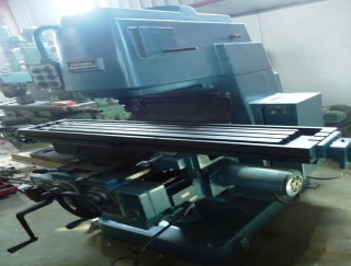
The FWTPET process is to generate the metallurgical and mechanical properties of work piece with robust weld joints and The FWTPET machine developed in- house is shown in Fig. 7.
|
|
|
Figure 7. FWTPET machine (developed in-house). |
The external tool consists of a shoulder and pin and the external tool used in this experiment is tungsten carbide. The tube and tube plate to be welded are well cleaned with air gun and set to free from all contaminants such as grease and absorbed film. The FWTPET machine consists of a tool holder, spindle, table and a supporting structure. The preferred dimension of hole was drilled at the centre of tube plate, and the tube was fitted and assembled to clamp in the machine wise with the support of backing block and specific setting conditions have been provided for each work piece and suitable amount of value is given as the input parameters.
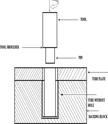
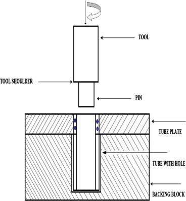
In this experiment, the tool is attached to the tool holder and then it is made to rotate at a required speed and the speed is varied for various conditions. Figure 8 and Figure 9 show the tool and work piece setup for tube without hole and tube with hole respectively. The tool is made to travel downwards towards the upper surface of the work piece and the required depth of cut and feed is given to the tool. Here, the friction will take place between the tool and the work piece due to the rotary force of the tool. The heat is generated between these materials. Backing block helps to withstand the downward force produced due to the tool rotation in the assembled work piece and an opposite force is produced. Due to these two converse forces, it builds to push the tool and the work piece tightly and tough optimal joint is made in the work piece. When the metal attains its melting temperature, the metal starts to plasticize and the metals start to move towards the centre of the tool axis and it fills the gap between the tool and the work piece.
|
|
|
Figure 8. Tool and work piece without hole. |
|
|
|
Figure 9. Tool and work piece with hole. |
The welding is carried out for both work pieces without hole and work pieces with hole on its circumference. In total, three sets of work pieces without hole on its circumference with various parameters have been welded and Fig. 10 shows the welded work piece assembly with hole and without hole.
|
|
|
Figure 10. Welded work piece with and without hole. |
2.3. Compression test
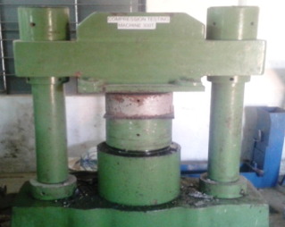
Compression tests are used to determine how a product or material reacts when it is compressed, squashed, crushed or flattened by measuring fundamental parameters that determine the specimen behaviour under a compressive load. These include the elastic limit, in which materials are approximately equal to the proportional limit, and also known as yield point or yield strength, young’s Modulus and compressive strength [13]. The compression test is mainly done to calculate the optimal joint strength of the welded work piece. The experiment is carried out on the work pieces with various parameters and obtain different compressive strength. The average value is considered for optimizing Taguchi and ANOVA methods. The compressive testing is done by the Universal Testing machine (UTM) and Fig. 11 shows the compression test specimen and the work piece is fixed in the UTM.
|
|
|
Figure 11. Universal testing machine – compression testing. |
2.4. Microstructural study
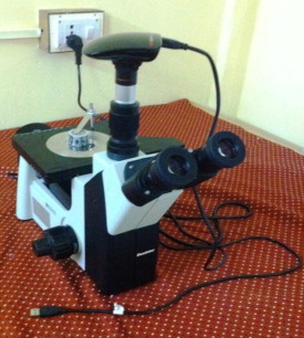
The micro structural characteristic of the friction welded joints was examined through the electronic optical microscope and the veracity of joints was analysed through the micrographs of the weld zone. After the welding operation, the work piece is sliced into smaller pieces for micro structural observation. The tube and tube plate joints are sliced into equal shape with the help of power hacksaw blade. The sliced pieces are then processed for cold setting done by the mixture of coal setting components such as coal setting liquid and coal setting powder. The more uneven scratches on the work pieces are removed by using dry belt machine. Then the fine scratches are removed using emery sheets with different sets of grade sheets. The chemical name called Nital etchant was applied on the work piece and it is made to dry in hot air for 10 s to get an enhanced micro structure of the work piece. The chemical composition of the NITAL etchant is 100 ml of Ethanol and 1–10 ml of HNO3[11]. This chemical is applied to the entire welded work piece which is obtainable to do micro structure with various magnifications. Fig. 12 shows the work piece which is fixed in the microscope to identify the microstructure of the welded work piece.
|
|
|
Figure 12. Work piece clamped in electron microscope. |
2.5. Vickers hardness test
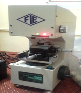
The hardness of the welded work piece has been measured by using Vickers hardness testing machine. The hardness value is obtained for two different conditions of the work piece are tube with hole and tube without hole. The Vickers hardness testing machine is shown in Fig. 13. The hardness has been measured at three different positions in tube and tube plate and three different positions are welding interface area, heat affected zone and the base metal.
|
|
|
Figure 13. Vickers hardness testing machine. |
3. Optimizing technique
In this study, the two techniques have been used to acquire the optimized results for obtaining the better joint strength for the welded work piece carried out by FWTPET process with the support of backing block during clamping in the milling machine. The two techniques used in this study are namely Taguchi and ANOVA methods.
3.1. Taguchi method
Taguchi method based robust design approach has produced a unique and powerful quality improvement discipline that differs from traditional practices. Taguchi approach can economically satisfy the need of problem solving and product/process design of optimization projects in the manufacturing industries [14]. Taguchi suggests signal to noise ratio (S/N) as the objective function for matrix experiments. The S/N ratio is used to measure the quality characteristics and is also used to measure the significant machining parameters through the ANOVA [15]. Taguchi classifies objective function into three categories, such as smaller the better type, larger the better type, and nominal the best type [16] and [17]. In this method, Taguchi larger the better type method is preferred to analyse the process parameters, the three process parameters that influence the joint strength are tool rotation speed, the tube projection and depth of cut and the value provided for the speed is about 545 rpm, 950 rpm and 1320 rpm, respectively. The tube projection given to the assembled tube and tube plate was given as 0 mm, 1 mm, 2 mm and depth of cut was 0.2 mm, 0.4 mm and 0.6 mm. The factors and their corresponding values for each level are shown in Table 4. The format of L9 orthogonal array is presented in Table 5.
| Factor | Levels | ||
|---|---|---|---|
| 1 | 2 | 3 | |
| A (tool rotating speed, rpm) | 545 | 950 | 1320 |
| B (projection, mm) | 0 | 1 | 2 |
| C (depth of cut, mm) | 0.2 | 0.4 | 0.6 |
| Experimental number | Input parameters | ||
|---|---|---|---|
| Tool rotational speed (rpm) | Tube projection (mm) | Depth of cut (mm) | |
| 1 | 1 | 1 | 1 |
| 2 | 1 | 2 | 2 |
| 3 | 1 | 3 | 3 |
| 4 | 2 | 1 | 2 |
| 5 | 2 | 2 | 3 |
| 6 | 2 | 3 | 1 |
| 7 | 3 | 1 | 3 |
| 8 | 3 | 2 | 1 |
| 9 | 3 | 3 | 2 |
3.2. ANOVA method
ANOVA is the statistical treatment most commonly applied to the results of experiments to determine the percentage contribution of each parameter. ANOVA helps in formally testing the significance of all main factors and their interactions by comparing the mean square against an estimate of the experimental errors at specific confidence levels [18]. To determine the optimal strength of the welding parameters, the standard ANOVA procedure was performed using the mean values. The ANOVA table indicates the order of importance of the welding parameters for the peak compression load of the friction welded work piece.
4. Results and discussion
The experimental process has been done for two conditions such as type 1 and type 2, in which, type 1 is a flat plate with plain tube and type 2 is flat plate with tube having holes on its circumference and welding carried out with the support of backing block. In both conditions, the Taughi method has identified the control factors to obtain the optimal better joint strength and ANOVA method has acknowledged the percentage of contribution for each parameter. The regression equation is used to identify the optimal joint strength for the both conditions.
4.1. Type 1 – tube without holes [WOH]
In this investigation, the tube plate and plain tube with no holes on its circumference with the support of backing block have been considered. In total, nine pieces were taken with three different set of parameters for friction welding. The experimental is conducted by the Taguchi L9 orthogonal array factors and three sets of levels. The three factors are tool rotating speed, tube projection and depth of cut subjected to be input parameters for the work piece to be welded. The compression strength is calculated for all the nine welded work pieces and the maximum compression strength obtained is 2980.50 MPa which is obtained at the speed of 545 rpm, projection 2 mm and depth of cut 0.6 mm. The output parameter compressive strength is obtained for all the nine values and it is given as the output parameters for calculating the mean and S/N ratio. Table 6 shows input and output parameters of FWTPET process according to L9 orthogonal array.
| Experiment number | Input parameters | Output parameters | ||
|---|---|---|---|---|
| Speed (rpm) | Projection (mm) | Depth (mm) | Compression strength (MPa) | |
| 1 | 545 | 0 | 0.2 | 2666.30 |
| 2 | 545 | 1 | 0.4 | 2827.90 |
| 3 | 545 | 2 | 0.6 | 2980.50 |
| 4 | 950 | 0 | 0.2 | 2962.56 |
| 5 | 950 | 1 | 0.4 | 2652.84 |
| 6 | 950 | 2 | 0.6 | 2380.44 |
| 7 | 1320 | 0 | 0.2 | 2639.37 |
| 8 | 1320 | 1 | 0.4 | 2558.57 |
| 9 | 1320 | 2 | 0.6 | 2438.96 |
4.1.1. Signal-to-noise ratio
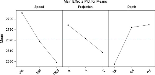
The important features are the joint strength for investigating the quality of FWTPET joints. The mean and Signal-to-Noise (S/N) ratio for the each factor have been calculated to assess the influence of factor on response. The criteria larger the better is considered for selecting the S/N ratio to make the most of response. The MINITAB software was used for determining the influence of process parameters (factors) on the joint strength (response). Table 7 provides the response table for means, and Table 8 provides the response table for S/N ratio. It is clear that a larger S/N ratio corresponds to better quality features. The mean effect and S/N ratio for joint strength were calculated by statistical software are shown in Figure 14 and Figure 15 respectively, indicating that the joint strength was at its maximum, with tool rotational speed of 545 rpm, tube projection of 2 mm, and plunge depth of 0.6 mm.
| Level | Speed | Projection | Depth |
|---|---|---|---|
| 1 | 2810.07 | 2551.15 | 2758.15 |
| 2 | 2671.15 | 2675.15 | 2675.15 |
| 3 | 2544.24 | 2799.15 | 2799.15 |
| DELTA | 265.83 | 248.00 | 248.00 |
| RANK | 1 | 3 | 2 |
| Level | Speed | Projection | Depth |
|---|---|---|---|
| 1 | −68.9737 | −68.1191 | −68.8123 |
| 2 | −68.5204 | −68.5324 | −68.5265 |
| 3 | −68.0969 | −68.9396 | −68.2522 |
| DELTA | 0.8768 | 0.8205 | 0.5601 |
| RANK | 1 | 3 | 2 |
|
|
|
Figure 14. Main effect plots for means – without holes. |
|
|
|
Figure 15. Main effect plot for S/N ratio [WOH]. |
The optimal joint strength for the welded work piece was maximum at the rotational speed 545 rpm, depth 0.6 mm and projection was 2 mm. This joint strength is acquired primarily due to the low speed of the tool rotation. The backing block supports the work piece and withstand the upward force produced due to the tool movement. Even the depth of cut of 0.6 mm and projection of 2 mm are put together in formation of rigid welding where more molten metals flow through the centre of the hole and this molten metal makes a better bonding in the work piece. When the rotating tool touches the work piece, the friction between the tool and work piece takes time to produce desired temperature to melt the metal due to the projection and the speed of the tool. When the tool moves downwards for a 0.6 mm depth of cut, the penetration of tool moves beyond the surface which makes the metal to melt and flow through the centre of axis of the tool to produce a better joint and stability. The backing block supports the work piece and provides an opposite force from the downward direction for better welding and joint strength.
4.1.2. ANOVA (analysis of variance)
Analysis of variance (ANOVA) test was carried out with a reason of identifying the process parameters that are statistically considerable and investigating the importance of the process parameters which influence the joint strength of FWTPET joints. In this study, MINITAB software is employed to estimate the percentage contribution of each process parameter to the overall joint strength. The obtained result of ANOVA is presented in Table 9. The calculated percentage explicates the most important process parameter is Speed of the tool about of 44.28% contribution, followed by tube projection (38.49%) and depth of cut (17.24%). Fig. 16 represents the interaction plot of means for compressive strength and the respective percentage of contributions is also graphically represented in Fig. 17 and Table 10 shows the percentage of contribution for each parameter.
| Source | DF | Seq. SS | Adj. SS | Adj. MS | F | P | Percentage of contribution |
|---|---|---|---|---|---|---|---|
| Speed, rpm | 2 | 106,066 | 106,066 | 53,033 | ∗∗ | 44.25 | |
| Projection, mm | 2 | 92,256 | 92,256 | 46,128 | ∗∗ | 38.49 | |
| Depth, mm | 2 | 41,334 | 41,334 | 20,667 | ∗∗ | 17.24 | |
| Error | 2 | 0 | 0 | 0 | 0 | ||
| Total | 8 | 239,656 | 100 |
Seq. SS, Sequential sum of squares; Adj. SS, adjusted sum of squares; Adj. MS, adjusted mean squares.
F – statistical test; P – statistical value.
|
|
|
Figure 16. Interaction plot – data means for comp strength [WOH]. |
|
|
|
Figure 17. Percentage contribution of process parameters [WOH]. |
| Experiment number | Input constraints | Output constraints | ||
|---|---|---|---|---|
| Speed (rpm) | Projection (mm) | Depth (mm) | Compression strength (MPa) | |
| 1 | 545 | 0 | 0.2 | 2531.60 |
| 2 | 545 | 1 | 0.4 | 2545.11 |
| 3 | 545 | 2 | 0.6 | 2560.21 |
| 4 | 950 | 0 | 0.2 | 2006.46 |
| 5 | 950 | 1 | 0.4 | 2019.92 |
| 6 | 950 | 2 | 0.6 | 2033.46 |
| 7 | 1320 | 0 | 0.2 | 2572.04 |
| 8 | 1320 | 1 | 0.4 | 2639.37 |
| 9 | 1320 | 2 | 0.6 | 2680.43 |
4.2. Type 2 – tube with holes [WH]
In this investigation, the tube plate and plain tube with no holes on its circumference with the support of backing block have been considered. In total, nine pieces were taken with three different set of parameters for friction welding. The experimental is conducted by the Taguchi L9 orthogonal array factors and three sets of levels. The three factors are tool rotating speed, tube projection and depth of cut subjected to be input parameters for the work piece to be welded. The compression strength is calculated for the all the nine welded work pieces and the maximum compression strength obtained is 2680.43 MPa which is obtained at the speed of 1320 rpm, projection 2 mm and depth of cut 0.6 mm. The output parameter compressive strength is obtained for all the nines values and it is given as the output parameters for calculating the mean and S/N ratio. Table 10 shows Input and output parameters of FWTPET process according to L9 orthogonal array.
4.2.1. Signal-to-noise ratio
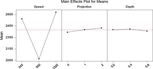
The important features are the joint strength for investigating the quality of FWTPET joints. The mean and Signal-to-Noise (S/N) ratio for the each factor have been calculated to assess the influence of factor on response. The criteria larger the better is considered for selecting the S/N ratio to make the most of response. The MINITAB software was used for determining the influence of process parameters (factors) on the joint strength (response). Table 11 provides the response table for means, and Table 12 provides the response table for S/N ratio. It is clear that a larger S/N ratio corresponds to better quality features. The mean effect and S/N ratio for joint strength were calculated by statistical software are shown in Figure 18 and Figure 19 respectively, indicating that the joint strength was at its maximum, with tool rotational speed of 1320 rpm, tube projection of 2 mm, and plunge depth of 0.6 mm.
| Level | Speed | Projection | Depth |
|---|---|---|---|
| 1 | 2379.72 | 2409.48 | 2386.28 |
| 2 | 2418.60 | 2417.48 | 2417.48 |
| 3 | 2454.12 | 2425.48 | 2448.68 |
| DELTA | 74.40 | 16.00 | 62.40 |
| RANK | 1 | 3 | 2 |
| Level | Speed | Projection | Depth |
|---|---|---|---|
| 1 | −67.5297 | −67.6367 | −67.5534 |
| 2 | −67.6709 | −67.6656 | −67.6667 |
| 3 | −67.7975 | −67.6959 | −67.7781 |
| DELTA | 0.2678 | 0.0593 | 0.2247 |
| RANK | 1 | 3 | 2 |
|
|
|
Figure 18. Main effect plots for means – with holes. |
|
|
|
Figure 19. Main effect plot for S/N ratio [WH]. |
The joint strength for the welded work piece was maximum at the rotational speed 1320 rpm, depth 0.6 mm and projection was 2 mm. It is obtained mainly due to the presence of projection and depth of cut given in the work piece. When the rotating tool touches the work piece, the friction takes place in quick manner and the heat is produced. When the tool moves downwards for a 0.6 mm depth of cut, the penetration of tool moves beyond the surface which makes the metal to melt and flow through the centre of axis of the tool to produce a better joint and stability.
4.2.2. ANOVA (analysis of variance) – process parameters
Analysis of variance (ANOVA) test was carried out with a reason of identifying the process parameters that are statistically considerable and investigating the importance of the process parameters which influence the joint strength of FWTPET joints. In this study, MINITAB software is employed to estimate the percentage contribution of each process parameter to the overall joint strength. The obtained result of ANOVA is presented in Table 13. The calculated percentage explicates the most important process parameter is Rotational speed of 57.17% contribution, followed by Depth of cut (40.1%) and Tube projection (2.64%). Fig. 20 represents the interaction plot of means for compressive strength and the respective percentage of contributions is also graphically represented in Fig. 21.
| Source | DF | Seq. SS | Adj. SS | Adj. MS | F | P | Percentage of contribution |
|---|---|---|---|---|---|---|---|
| Speed, rpm | 2 | 8308.7 | 8308.7 | 4154.3 | ∗∗ | 57.17 | |
| Projection, mm | 2 | 384.0 | 384.0 | 192.0 | ∗∗ | 2.64 | |
| Depth, mm | 2 | 5840.6 | 5840.6 | 2920.3 | ∗∗ | 40.1 | |
| Error | 2 | 0.0 | 0.0 | 0.0 | 0 | ||
| Total | 8 | 14533.3 | 100 |
Seq. SS, sequential sum of squares; Adj. SS, adjusted sum of squares; Adj. MS, adjusted mean squares.
F – statistical test; P – statistical value.
|
|
|
Figure 20. Interaction plot – data means for comp strength [WH]. |
|
|
|
Figure 21. Percentage of contribution [WH]. |
5. Comparison of two techniques
The comparison of both work piece without holes and work piece with holes in support of backing block is done by four techniques, the first techniques is the percentage of contribution by each factor, second techniques is regression analysis, the third method is micro structure analysis for each sample of welded work piece and fourth technique is the measurement of hardness value of the welded work piece at four different places. From these four techniques, the value of optimal joint strength (compression test) has been identified and the factors influence the work piece for better joint strength in the welded joint. The comparison of both mechanical and metallurgical properties has been discussed and validated.
5.1. Percentage of contribution
The software MINITAB is used to calculate the percentage for contribution of each factor for obtaining optimal joint strength. The most influencing factor for better joint strength is speed of the tool rotation has value of about 44.25% and 57.17% for work piece with hole and work piece with hole respectively. The rotating speed (rpm) is dominating factor for manipulating the joint strength when compared to other two factors such as Projection and depth of cut. In this study, the percentage of contribution is high in case of tool rotation and tube projection for work piece without hole. Table 14 shows the compared value for the percentage of contribution.
| Factors | Percentage of contribution (%) | |
|---|---|---|
| Without hole (WOH) | With hole (WH) | |
| Speed (rpm) | 44.25 | 57.17 |
| Projection (mm) | 38.49 | 2.64 |
| Depth (mm) | 17.24 | 40.1 |
5.2. Regression analysis for joint strength
The regression analysis is mainly used to find out the prediction values and forecasting. It is also widely used to understand which among the independent variables are related to the dependent variable, and to explore the forms of these relationships. The optimal joint strength for work piece with hole is obtained by means of regression analysis using MINITAB. In this study, the regression equation is obtained by means of both input parameters such as speed, projection and depth of cut and output factor such as compressive strength which is given to the Taguchi L9 orthogonal array method.
5.2.1. Type 1: tube without holes [WOH]
The corresponding value of input factors is considered for calculating the optimal joint strength of work piece by using regression equation based on the maximum value obtained in the output parameter is compression strength. The maximum compressive strength for without hole is 2980.50 MPa and corresponding values for each factor speed, projection, and depth are 545 rpm, 2 mm and 0.6 mm respectively. The values are substituted in the equation provided. The attained value is joint strength for the particular input and output factor which have been considered in the Taguchi L9 orthogonal array factors and levels.
|
|
(1) |
5.2.2. Type 2: tube with holes [WH]
The corresponding value of input factors is considered for calculating the optimal joint strength of work piece by using regression equation based on the maximum value obtained in the output parameter compression strength. The maximum compressive strength for without hole is 2680.43 MPa and corresponding values for each factor speed, projection, and depth are 1320 rpm, 2 mm and 0.6 mm respectively. The values are substituted in the equation provided. The attained value is joint strength for the particular input and output factors which have been considered in the Taguchi L9 orthogonal array factors and levels.
|
|
(2) |
5.3. FWTPET sample welded
Friction welding of tube to tube plate work piece is examined under the microscope to explore the mechanical and metallurgical properties and change in bonding structure of welded work piece. In this method, both work piece without holes and work piece with holes are carried out for microscopic sample test. The microstructure of various zones in welded work piece is taken as base metal of tube and plate, welded interface zone and the heat affected zone.
5.3.1. Type 1: tube without holes [WOH]
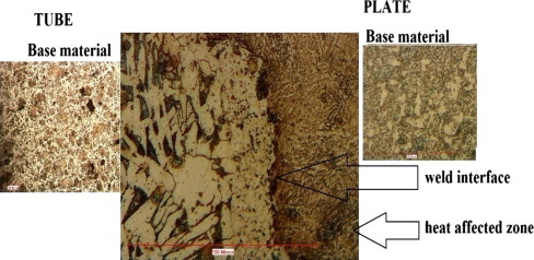
The micro structure analyses were carried out with various samples taken at optimized condition for the work piece without holes on its circumference. Fig. 22 shows the microstructure sample of the optimal joint strength of the work piece with various zones with input parameters such as speed, projection and depth of cut was 545 rpm, 2 mm and 0.6 mm, respectively.
|
|
|
Figure 22. Microstructure of weld joint obtained by FWTPET process showing crack free interface (WOH). |
The microstructure of the welded sample workpiece with hole discloses that better bonding has been achieved between the tube and plate due to the absence of holes on its circumference, and this leads to no change in bonding structure of the work piece before welding. In this study, the sample welded has a projection of 2 mm which makes metal to melt slowly and possess depth of cut of 0.6 mm and hence the friction takes place between the tube and plate at very slower rate due to the tool rotation speed of 545 rpm. This makes the formation of weld joint slowly and steadily to pour the molten metal all over the surface and its centre to have a better bonding and joint strength. The continuous layer is essentially an alloy composed of the two parent materials. It is thought to be caused because of the instantaneous heat generated by the severe plastic deformation encountered at the interface [19]. When the metal attains its melting temperature, a continuous layer of fusion zone has been formed at the joint interface. In the present study, the interfaces are uninterrupted and emerge as a separate line even at better magnification and a fusion zone is also observed on the welded part of the bond boundary in the work piece. The micro structure shows the fine grained ferrites near the bonding line and this is due to combined effect of rigorous plastic deformation and higher nucleation pace.
5.3.2. Type 2: tube with holes [WH]
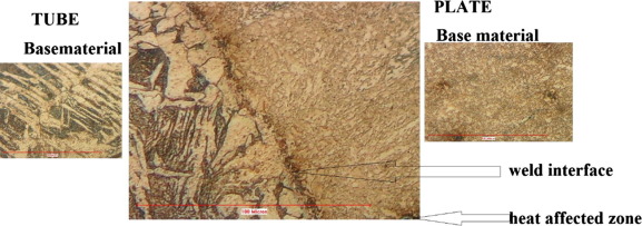
The micro structure analyses were carried out with various samples taken at optimized condition for the work piece with holes of 2 mm diameter on its circumference. Fig. 23 shows the microstructure sample of the optimal joint strength of 2680.43 MPa of the work piece with various zones with input parameters such as speed, projection and depth of cut was 1320 rpm, 2 mm and 0.6 mm, respectively.
|
|
|
Figure 23. Microstructure of weld joint obtained by FWTPET process showing crack free interface (WH). |
In this study, the bonding structure forms due to the rotation speed of the tool with depth of cut. During rotation, the tool shoulder touches the plate and it undergoes plastically deformed condition and forms a bond. The micrograph reveals that the metallurgical bonding between tube and tube plate has been achieved. The joint strength of the work piece with hole is less when compared to the work piece without hole mainly because of the holes present in the work piece. The dislocation of atoms in the bonding structure had been occurred while the holes are made in the work piece before the welding. During the welding, the tube metal melts and undergoes plastic deformation condition. Hence the metal flow occupies the hole in the tube and forms a bond between them.
5.4. Hardness measurement
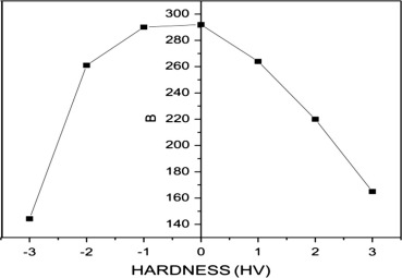
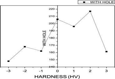
The micro hardness testing was conducted for the welded work piece with optimal joint strength through FWTPET process. Hardness values are obtained using a Vickers hardness micro testing with a load of 1 kg, and a loading time of 25 s for each sample. The micro hardness has been calculated for both work pieces without hole and with hole at various zones such as base metal of tube and plate, heat affected zone of tube and plate, refined zone of tube and plate, weld interface. Fig. 24 compares the value of micro hardness plot of the sample welded work piece without hole and with hole on its circumference. Table 15 shows the harness value for each zone for both work pieces without holes and with holes.
|
|
|
Figure 24. Comparison of hardness profile of FWTPET sample of tube without hole [WOH] and with hole [WH]. |
| S. No. | Hardness measurement at different zones | Hardness value (Hv) tube without hole | Hardness value (Hv) for tube with hole |
|---|---|---|---|
| 1 | Base tube | 144.3 | 148 |
| 2 | Heat affected tube | 261 | 168 |
| 3 | Knuched tube | 290 | 162 |
| 4 | Welded interface | 292 | 206 |
| 5 | Knuched plate | 264 | 196 |
| 6 | Heat affectedplate | 220 | 217 |
| 7 | Base plate | 165 | 161.25 |
5.4.1. Type 1: tube without holes [WOH]
The optimal joint strength of the work piece is achieved through each parameters of speed (545 rpm), projection (2 mm) and depth of cut (0.6 mm) of sample welded work piece without hole. The hardness of the optimal joint strength work piece has been tested at different weld conditions and welding interface hardness possessed higher hardness value of about 292 Hv. Fig. 25 shows the harness of work piece without hole on its circumference. The hardness value at the interface for the work piece without holes is higher when compared to the work piece with hole due to the fine refinement of the grains at the weld interface and optimum heat generation is produced in between tube to tube plate for achieving good mechanical and metallurgical bond [20] and [21].
|
|
|
Figure 25. Micro hardness plot – WHO. |
5.4.2. Type 2: tube with holes [WH]
The optimal joint strength of the work piece is achieved through each parameters of speed (1320 rpm), projection (2 mm) and depth of cut (0.6 mm) of sample welded work piece without hole.
The hardness of the optimal joint strength work piece has been tested at different weld conditions and welding interface hardness possessed hardness value of about 217 Hv. Fig. 26 shows the hardness value of work piece with hole on its circumference. The hardness value at the interface for the work piece with hole is lower when compared to the work piece with hole due to the refinement of the grains at the weld interface and minimum heat generation is produced in between tube to tube plate.
|
|
|
Figure 26. Micro hardness plot – WH. |
6. Conclusion
The friction welding has been successfully carried out and produced a high quality welding with flaw free weld joint for the material SA 213 tube and parent material SA 387 tube plate where it posses many industrial and power plant applications such as boiler, box type heat ex-changer and radiator tubes etc. Taguchi L9 orthogonal array was used in this study for both types, work piece without holes and work piece with holes on its circumference. The most influential process parameter in deciding the joint strength is identified as projection involved in the tube without hole and the maximum compression strength obtained is 2980 MPa which is obtained at the speed of 545 rpm, projection 2 mm and depth of cut 0.6 mm. The optimal joint strength is higher in the work piece without holes than the work piece with holes. The ANOVA method calculated the percentage of contribution of each process parameter where rotational speed with highest percentage (44.25%) is followed by the projection (38.49%) and depth of cut (17.24%). The microstructure proves the fine grain enhancement has been occurred in the welding interface which possess a high joint strength and hardness of the work piece. The welded interface of tube without holes is found to be better when compared with work piece with holes on its circumference. The development of continuous layer at the boundary leads to improved bonding between the different metals. The micro hardness graph exemplifies that hardness of the work piece without hole has a higher value of 292 Hv when compared with work piece with holes of 217 Hv.
Acknowledgments
The authors like to convey profound gratitude to the Department of Science and Technology, New Delhi and Financial support release under “Young Scientist Scheme” through Science and Engineering Research Board (SERB/FTP/ETA/0282/2013) for this research project. The authors like to express sincere thanks to Research & Development centre for providing the ambient laboratory facilities at RVS School of Engineering & Technology, Dindigul, Tamil Nadu.
References
- [1] S. Muthukumaran, A process for friction welding tube to a tube sheet or plate by adopting an external tool, Indian patent Application No. 189/KOL/06 filed on 07-03-2006, Patent No. 217446, 2006 (granted on 26-03-2008).
- [2] W.M. Thomas, E.D. Nicholas; Friction-stir welding for the transportation industries; Mater. Des., 18 (1997), pp. 269–273
- [3] R.S. Mishra, Z.Y. Ma; Friction-stir welding and processing; Mater. Sci. Eng., R, 50 (2005), pp. 1–78
- [4] S. Senthil Kumaran, S. Muthukumaran, S. Vinodh; Optimization of friction welding of tube to tube plate using an external tool; Struct. Multidisc Optimiz. (2010) http://dx.doi.org/10.1007/s00158-010-0509-7
- [5] P. Sathiya, S. Aravindan, A. Noorul Haq, K. Paneerselvam; Mater. Process. Technol., 209 (2009), pp. 2576–2584
- [6] S. Muthukumaranan, C. Vijaya Kumar, S. Senthil Kumaran, A. Pradeep; Interfacial microstructure and strength of friction welding of steel tube to aluminium tube plate using an external tool; Adv. Mater. Res., 383–390 (2012), pp. 877–881
- [7] S. Senthil Kumaran, S. Muthukumaran, S. Vinodh; Optimization of friction welding of tube-to-tube plate using an external tool by Taguchi method and genetic algorithm; Int. J. Adv. Manuf. Technol., 57 (2011), pp. 167–182
- [8] S. Muthukumaran, Friction welding of tube to tube plate using an external tool: a study, in: International Welding Symposium 2k10, Mumbai, India, 2010, pp. 241–245.
- [9] P.L. Mangonon; The Principles of Materials Selection for Engineering Design; Prentice-Hall (1999)
- [10] S. Senthil Kumaran, S. Muthukumaran, C. Chandrasekhar Reddy; Effect of tube preparations on joint strength in friction welding of tube-to-tube plate using an external tool process experimental techniques; Soc. Exp. Mech., 37 (2013), pp. 24–32 © 2011
- [11] Donald Zipperian; Chemical etching; PACE Technol., II (5) (2003)
- [12] V.L. Popov; Contact Mechanics and Frictions: Physical Principal and Application; Springer, London (2010)
- [13] H. Schmidt, J. Hattel; Modelling heat flow around the tool probe in friction stir welding; Sci. Technol. Weld. Join., 10 (2) (2005), pp. 176–186
- [14] R.F. Speyer; Thermal Analysis of Materials; Marcel Dekker (1994)
- [15] M.E. Brown; Introduction to Thermal Analysis; Kluwer (2001)
- [16] G. Taguchi; Introduction to Quality Engineering; Mc-Graw Hill, New York (1986)
- [17] M.S. Phadke; Quality Engineering Using Robust Design; Prentice Hall Int., New Jersey (1989)
- [18] N.H.M. Nor, N. Muhamad, K.R. Jamaludin; Optimization of injection molding parameter of Ti–6Al–4V powder mix with palm stearin and polyehylene for the highest green strength by using Taguchi method; Int. J. Mech. Mater. Eng., 6 (2011), pp. 126–132
- [19] MINITAB_ (2008) MINITAB_Statistical Software, Release 15, State College.
- [20] G.K. Balaji, S. Muthukumaran, S. Senthilkumaran, A. Pradeep; Optimization of friction welding of tube to tube plate using an external tool with filler plate; J. Mater. Eng. Perform. [ASM International], 21 (7) (2012), pp. 1199–1204
- [21] M.M. Schwartz; Metals Joining Manual; McGraw-Hill Book Company, USA (1979)
Document information
Published on 12/04/17
Licence: Other
Share this document
Keywords
claim authorship
Are you one of the authors of this document?

![Tube with hole [WH].](/wd/images/6/65/Draft_Content_657992681-1-s2.0-S1110016816300722-gr4.jpg)

![Main effect plot for S/N ratio [WOH].](/wd/images/c/c6/Draft_Content_657992681-1-s2.0-S1110016816300722-gr15.jpg)
![Interaction plot – data means for comp strength [WOH].](/wd/images/d/d0/Draft_Content_657992681-1-s2.0-S1110016816300722-gr16.jpg)
![Percentage contribution of process parameters [WOH].](/wd/images/c/c3/Draft_Content_657992681-1-s2.0-S1110016816300722-gr17.jpg)
![Main effect plot for S/N ratio [WH].](/wd/images/7/7b/Draft_Content_657992681-1-s2.0-S1110016816300722-gr19.jpg)
![Interaction plot – data means for comp strength [WH].](/wd/images/c/c0/Draft_Content_657992681-1-s2.0-S1110016816300722-gr20.jpg)
![Percentage of contribution [WH].](/wd/images/4/4a/Draft_Content_657992681-1-s2.0-S1110016816300722-gr21.jpg)
![Comparison of hardness profile of FWTPET sample of tube without hole [WOH] and ...](/wd/images/1/15/Draft_Content_657992681-1-s2.0-S1110016816300722-gr24.jpg)
