1 Introduction
With the increased use of composite materials in aircraft structures, impact protection is also growingly important as these materials, which are lighter and more efficient than their metal counterparts, are more prone to impact damage, potentially reducing system performance. This topic is of particular interest in unmanned flight systems that carry payloads to and from harsh environment locations which are prone to ballistic impacts. It is imperative that the vehicle is able to complete the flight cycle and, therefore, the integrity of the flight control systems is of the highest importance in order to keep the vehicle in-service. This means that the structure, or at least the vicinity of the flight control systems, must be able to sustain ballistic impacts whilst maintaining the flight control. Design of such structural components is linked to the proper understanding of the materials used in an impact tolerant solution. The proposed approach in this investigation is to identify potential materials to resist an impact from a high energy projectile that may be coupled with the base structural composite material and still result in a low weight increase of the structure. The implemented methodology in the design and validation process is to subject the selected composites, as well as the combination of the composite and protective layer materials to ballistic impacts in a controlled environment. Numerical material models that capture the material behaviour in this extreme loading scenario, are developed and validated with the experimental data. This investigation looks at a ceramic based material to act as the protective agent over a load carrying carbon fibre reinforced polymer (CFRP) plate, responsible for the structural stability of the aircraft. Different modeling techniques are implemented as well as several damage models which are addressed to find the most suitable combination for the present mechanical solicitation scenario.
1.1 Background
A multi-layered ballistic armour consists of the combination of different materials with specific functions. Generally, a ballistic armour incorporates a ceramic layer, a backing composite laminate and, in some cases, a spall shield (covering the ceramic). A ceramic layer is normally placed on the strike face, preferably perpendicular to the expected threat [1]. High-performance ceramic materials, such as alumina (Al2O3), silicon carbide (SiC), boron carbide (B4C) or silicon nitride (Si3N4) [2], are renowned for their high hardness and strength and relatively low brittleness, when compared with other ceramics. Therefore, they are responsible for shattering the bullet and absorbing the primary impact energy [3]. The protective armour material can incorporate a single or multiple ceramic elements (multi-piece). The use of multiple ceramic components, usually triangles, squares or hexagons, allows for a much wider range of configurations, such as multi-curved and complex geometries [2], [4]. Additionally, the integration of smaller tiles promotes the protection against multi-impacts, although this can be affected by the type of interface. The ceramic components can be directly abutted or some distance between them can be kept with or without damping material at the joint [4]. Statistically, interfaces associated to the incorporation of hexagonal ceramic elements have a slightly lower impact vulnerability than those with the other geometries [5].
The energy dissipation mechanism is associated not only to the projectile spalling but also to the ceramic fragmentation [6], [7]. In order to ensure the bullet remaining kinetic energy absorption, a single or multiple backing layers are added to the armour [6], [8].
In the modern ballistic armours, a composite layer usually supports the ceramic tile(s). UHMWPE and Kevlar composites are commonly used as armour backing layers due to their outstanding impact shock wave absorption capacity [6]. Carbon and glass fibre composites can also be a viable solution in some specific situations. Such an example is if the structural integrity or cost are a priority.
Regarding the spall shield, it covers the ceramic front surface and protects the component and the armour itself from the fragments blast. It may be a synthetic plastic sheath, a thermoplastic sheath, a polycarbonate sheath or a polymer-encased reinforcement layer (e.g. high tensile strength fine steel wire mesh or glass fibre embedded in a polymer). Self-sealing materials such as vulcanized rubber, including polyurethane elastomers and silicone, are also commonly used. These materials are able to close upon a punctured hole created by the incoming projectile and thus the size of the hole is smaller than the size of the ceramic tiles; this contributes to the ceramic protection [1], [9], [10].
2 Materials and processes
2.1 Carbon fibre reinforced polymer plates
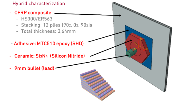
The structural base CFRP material chosen for this investigation was HS300/ER563 UD composite. The stacking sequence was [902, 02, 902]S for a total of 12 plies. The 200 x 200 mm2 plates were cured in an autoclave following the manufacturer’s instructions resulting in a final cured thickness of 3.64 mm.
2.2 Ceramic plates
The ceramic plates were pressureless sintered in a N2 atmosphere. Hexagonal plates were produced using two different powder sources: 1) Commercially available spray dried Si3N4 powder with sintering aids and organic binders. 2) An in-house developed matrix formulation, using Al2O3 and Y2O3 sintering aids. After pressing, the samples were heated in an oven to remove the organic compounds (calcination). Both the samples from the commercial powder and the matrix were sintered inside a crucible filled with a powder bed to prevent decomposition (50 % matrix powder + 50 % of BN powder). The sintering temperature of the hexagonal samples was 1700 °C / 3 h dwell time. The resulting ceramic hexagons had an average thickness of 3.8 mm.
2.3 Processing the multi-material solution
The ceramic hexagons were manually placed on top of the CFRP plates using a MTC510 epoxy adhesive film in between. The assembly was then subjected to a post-cure in the autoclave following the adhesive film manufacturer’s instructions (Figure 1). Of note that this post-cure is performed at a lower temperature and pressure of those needed to process the base materials (CFRP and ceramic).
3 Experimental test campaign
Two groups of samples were subjected to experimental ballistic tests in controlled environment in a total of 6 tested samples; 3 composed only of CFRP material (base group) and another 3 that had the ceramic hexagons bounded to the CFRP base plate. The projectiles were 9 mm lead bullets fired at a distance of 10 m of the target. Impact velocity was measured by means of a laser chronograph and residual velocity with a high speed camera. The average impact speed considering all tests was 335 m/s and the residual speed was 333 m/s and 164 m/s for the CFRP and the CFRP-ceramic plates, respectively.
4 Numerical models
The finite element commercial package Abaqus® was used to perform all numerical investigations. The Eulerian-Lagrangian method was employed to model the different components/materials, where the CFRP and ceramic are modelled as 3D Lagrangian elements and the bullet as Eurelian with no casing and implemented having lead as the material.
The MTC510 epoxy adhesive film, between the CFRP and the CFRP, is modeled using two different cohesive law techniques, by means of 3D cohesive elements or using a cohesive contact formulation. A similar approach is adapted to capture the ceramic behaviour where the material model implemented was the JHB or the JH-2 [11] applied to C3D8R elements. Finally, the CFRP is modelled using C3D8R elements, an extrapolation of the Hashin failure criteria [12] to 3D was implemented for the this material, with no damage propagation, by means of a VUMAT user subroutine. The bullet is modeled as an elastic/plastic medium using Eurelian mesh elements.
Table 1, 2, 3 and 4 summarize the material properties necessary for each component as per each respective chosen damage criteria and Figure 2 shows a schematic of the numerical test apparatus.
| Property | Value | Unit |
| Density | 1.60 x 10⁹ | ton/mm3 |
| E1 | 139600 | MPa |
| E2 / E3 | 8665.93 | MPa |
| v12 / v13 | 0.26 | -- |
| v23 | 0.38 | -- |
| G12 / G13 | 3610.80 | MPa |
| G23 | 2145.76 | MPa |
| Xt | 2740 | MPa |
| Xc | 2107.20 | MPa |
| Yt / Zt | 37.47 | MPa |
| Yc / Zc | 137.77 | MPa |
| S12 / S13 /S23 | 46.36 | MPa |
| Property | Value | Units |
| Density | 1.59 x 10⁹ | ton/mm3 |
| E / Enn | 1.0 x 10⁶ | (high number) |
| G1 / Ess | 1.0 x 10⁶ | (high number) |
| G2 / Ett | 1.0 x 10⁶ | (high number) |
| Nominal stress | 60 | MPa |
| Nominal stress 1st and 2nd directions | 55 | MPa |
| Normal mode fracture energy | 0.489 | N/mm |
| Shear mode fracture energy 1st and 2nd directions | 0.31 | N/mm |
| Viscosity coefficient | 1.0 x 10⁻⁵ |
| Property | Value | Units |
| Density | 3.23 x 10⁹ | ton/mm3 |
| G | 120000 | MPa |
| A; N; B; M | 0.96; 0.65; 0.35; 1 | -- |
| C; e0 | 0.009; 1 | |
| T | 800 | MPa |
| gi_max; gf_max | 1.24; 0.13 | -- |
| HEL | 11700 | MPa |
| p_HEL | 5130 | MPa |
| beta; D1; D2 | 1; 0.48; 0.48 | N/mm |
| epl_max; epl_min; FS | 1.2; 0; 0.2 | N/mm |
| K1; K2; K3 | 220000; 361000; 0 | MPa |
| Property | Value | Units |
| Density | 1.13 x 10⁸ | ton/mm3 |
| Young’s modulous | 13800 | MPa |
| Poisson coefficient | 0.42 | -- |
| Yield stress | 5 @ 5% | MPa |
| Strength | 18 @ 75% | MPa |
5 Results and discussion
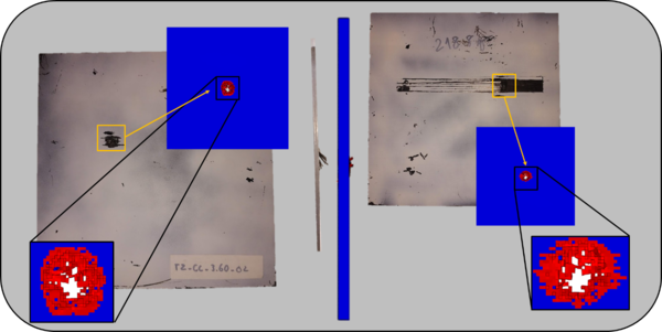
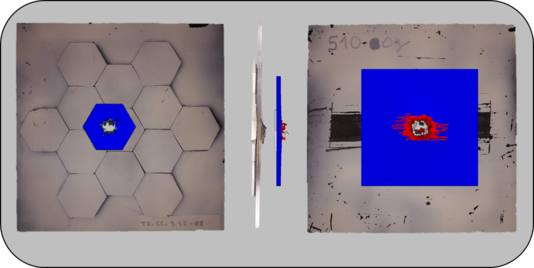
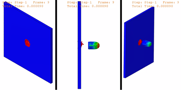
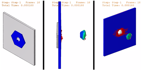
The model response to a ballistic impact event for the CFRP and for the CFRP-ceramic hybrid plates is depicted in Figures 3 and 4. As can be observed, the bullet almost suffers no deformation impacting the CFRP plate and the damaged area is very limited to the area where there is penetration. The oposite occurs when the bullet penetrates the CRFP-ceramic plate where it signifficantly deforms, since most of the energy is dissipated in the ceramic material therefore, less energy is left in the projectie, nevertheless this remainder of energy is enough to pass through the fibers of the CFRP but, since the energy is lower, it is dissipated in an area considerably larger.
Table 7 and 8 summarize the results of the experimental measurements and the residual velocity obtained with the numerical models. Figure 5 and 6 show the experimental results overlapped with the numerical data for the CFRP plate and for the CFRP plate with ceramic protection respectively. There is good correlation between the model and the experimental results when comparing the residual velocities.
| Formulation | Initial velocity | Residual velocity |
| CFRP | 335 m/s | 333 m/s |
| CFRP + ceramic | 335 m/s | 164 m/s |
| Formulation | Cohesive contact | Cohesive 3D elements |
| CFRP | 328 m/s with no cohesive formulations | |
| CFRP + ceramic JHB | 251 m/s | 280 m/s |
| CFRP + ceramic JH-2 | 162 m/s | 143 m/s |
As can be observed, some modeling techniques are able to capture the residual velocity / energy properly, where others are inadequate. For the scenario under investigation, the modeling approach used to capture the impact of the bullet on a HS300/ER563 UD composite CFRP plate by means of the Hashin failure criteria using 3D C3D8R elements, has shown that there is excelent correlation between the model and the experimental results with a difference of only 1.5 % when comparing the average of the experimentally measured residual velocity (333 m/s) and the value determined using the finite element method (328 m/s).
With the hydrid solution results and analysis, i.e. ceramic hexagonal tiles integrated into the CFRP plate, one can observe that the modeling solution that has better correlation with the experimental data is a combination of using a cohesive contact formulation, between the ceramic tiles and the CFRP plate, and implementing the JH-2 ceramic damage model to the hexagonal tile keeping the same modeling technique as discussed previously for the CFRP plate. The average of the measured experimental velocity was 164 m/s and the value determined in the aforementioned modeling scenario was 162 m/s, this represents a difference of 1.2 % of error between the numerical model and the experimental results.
6 Conclusions
It is shown that the implemented models are able to properly capture the residual velocity for the two impact scenarios under investigation for a hybrid material solution which involves different material models and modeling techniques. It is clear that for the purpose of design, a thicker plate is required to avoid penetration of the structure of the aircraft. Nevertheless the projectile speed was decreased by about 51 % (from 335m/s to 164m/s in average) when using a 3.8 mm ceramic plate. Of course this increase in thickness poses a challenge since, more material directly translates to an increase in weight.
7 Future work
The only assessed variable in the present work was the residual velocity. Nevertheless, it is highly impotant to address the damage extension in the structural components for impact scenarios where there is complete penetration of the structure and when the projectile is stopped inside the material. In particular, the case where the bullet is stopped inside the material, it is expected that damage by delamination is responsible for dissipating a high level of projectile energy. Therefore it is expected that modeling the interply sections of the CFRP will be a requirement to capture this failure mechanism.
It was concluded that thicker ceramic tiles are needed to stop the projectile, however the direct increase in weight of the solution may render it invalid. The weight is of high importance in the current aircraft industry segment. Nevertheless, the intrinsic capacity of the ceramic to shatter the projectile upon impact makes it imperative in the use as the first line of defense in the present protection systems. Therefore, the investigators believe that the solution will be a combination of more materials, keeping the present ceramic thickness, and having a second layer made out of HB26 or another emerging material, for example. This will allow to increase the thickness, the energy absorption capability, and absorb part of the deformation of the ceramic. Nevertheless HB26 implementation brings a new layer of complexity to the models since it is a fabric. Regardless of these suppositions and suggestions future investigation needs to be carried out in this direction to find the optimal balance between cost and weight of the solution and should always be taylored and optimized to the design requirements.
Acknowledgements
Authors gratefully acknowledge the funding of Project POCI-01-0247-FEDER-017751 – ALIR_mcs, cofinanced by Programa Operacional Competitividade e Internacionalização (Compete 2020), through Fundo Europeu de Desenvolvimento Regional (FEDER).”
References
[1] CeramTec - ETEC GmbH, “Ceramic Materials for light-weight Ceramic Polymer Armor Systems.”
[2] J. Jiusti et al., “Ballistic performance of Al2O3 mosaic armors with gap-filling materials,” Ceram. Int., vol. 43, no. 2, pp. 2697–2704, Feb. 2017.
[3] E. Medvedovski, “Advances in Applied Ceramics Structural, Functional and Bioceramics Lightweight ceramic composite armour system Lightweight ceramic composite armour system,” 2013.
[4] L. Bracamonte, I. K. Yilmazcoban, and R. Loutfy, “Design, manufacture, and analysis of ceramic-composite armor,” in Lighweight Ballistic Composites: Military and Law-Enforcement Applications, 2nd ed., 2016, pp. 349–367.
[5] S. J. Bless and D. L. Jurick, “Design for Multi-hit Capability,” Int. J. Impact Eng., vol. 21, no. 10, pp. 905–908, 1998.
[6] E. Medvedovski, “Ballistic performance of armour ceramics: Influence of design and structure. Part 1,” Ceram. Int., vol. 36, no. 7, pp. 2103–2115, Sep. 2010.
[7] F. Santos da Luz, E. P. L. Junior, L. H. L. Louro, and S. N. Monteiro, “Ballistic Test of Multilayered Armor with Intermediate Epoxy Composite Reinforced with Jute Fabric,” Mater. Res., 2015.
[8] W. Liu et al., “Influence of different back laminate layers on ballistic performance of ceramic composite armor,” Mater. Des., vol. 87, pp. 421–427, 2015.
[9] Lucuta, “Ceramic Armour Systems with a Front Spall Layer and a Shock Absorbing Layer,” US 6912944 B2, 2005.
[10] I. Moore, “Encapsulated Ceramic Composite Armour,” US 7866248 B2, 2011.
[11] T. J. Holmquist and G. R. Johnson, “Characterization and evaluation of silicon carbide for high-velocity impact,” J. Appl. Phys., vol. 97, no. 9, p. 093502, May 2005.
[12] Z. Hashin and A. Rotem, “A Fatigue Failure Criterion for Fiber Reinforced Materials,” J. Compos. Mater., vol. 7, no. 4, pp. 448–464, Oct. 1973.
Document information
Published on 17/01/21
Accepted on 04/07/19
Submitted on 04/05/19
Volume 05 - Comunicaciones Matcomp19 (2021), Issue Núm. 1 - Comportamiento en servicio – Inspección y reparación., 2021
DOI: 10.23967/r.matcomp.2021.01.010
Licence: Other
Share this document
Keywords
claim authorship
Are you one of the authors of this document?

