Abstract
The design and evaluation of parachute-payload systems is an important field of applications in which numerical analysis tools can make very important contributions. This work describes new numerical developments carried out at CIMNE in this field, which involve a coupled fluid-structural solver intended for the unsteady simulation of ram-air type parachutes and a set of complementary tools aimed at studying trajectory and control systems effects. For an efficient solution of the aerodynamic problem, an unsteady panel method has been chosen exploiting the fact that large areas of separated flow are not expected under nominal flight conditions of ram-air parachutes. Besides, a dynamic explicit solver based on a finite element technique is chosen for the structure. This approach yields a robust solution even when highly non-linear effects due to large displacements and material asymmetric behaviours are present. The numerical results show considerable accuracy and robustness. An added benefit of the proposed aerodynamic and structural techniques is that they can be easily vectored and thus suitable for use in parallel architectures.
The main features of the developed computational tools are described in this work and several numerical examples are provided to illustrate the good performance and potential of the proposed techniques. Further improvements of the methodology being carried out and future lines of investigation are also presented.
1. INTRODUCTION
The numerical simulation of parachutes is a challenging problem mainly due to fact that geometry is complex in design and behaviour and, in addition, it is continuously varying in time. From the aerodynamic point of view several factors related to intricate unsteady flow processes must be taken into account. Among these it can be found massive flow separation, complex aerodynamic interactions between the structural components and the presence of large unsteady wakes. The structural analysis requirements are also important. It is necessary to simulate the behaviour of light structures which, in general, are not statically determinate for an arbitrary set of loads (i.e. they behave like a mechanism). Thus, drastic changes in geometry are needed in order to reach an equilibrium state; the structural response is highly non-linear and this may cause severe numerical convergence problems. In addition, complexity of the structural model is increased by the need to simulate ribbon reinforcements integrated into the fabric and cords for supporting and control purposes. Due to the lack of bending stiffness of the structural components, the materials are able to resist tensile stresses but buckle (wrinkle) under compressive loads. This asymmetric behaviour should also be accounted for. Finally, the nature of the applied forces and the structural response of the parachute add extra difficulties to the analysis. The magnitude and direction of the forces, which are mostly due to pressure loads, are not known in advance but are a function of the deformed parachute shape; therefore, they must be computed as part of the solution. Furthermore, the pressure field presents high sensitivity to changes in geometry requiring iterative solution procedures.
The numerical simulation of parachutes must deal with all the issues listed above pursuing reliability and reasonable computational costs. The challenges to be faced are important and this explains why the current design of parachute systems relies mostly on empirical methods. As an example, 15 worldwide parachute manufacturers were recently surveyed about the use of computational tools in the design and evaluation of parachute systems [1]. All of ten responses received deny the employment of simulation software, with the exception of computer assisted design (CAD) tools. This is a clear indication that computational mechanics is hardly applied to parachute design. The numerical simulation tools described in this work are intended to address this shortcoming.
1.1 Previous developments on parachute simulation at CIMNE
Most challenging situations involved in the numerical simulation of parachutes have been addressed at CIMNE and several analysis tools have been developed to tackle those problems. At present, CIMNE has gained experience in the field of parachute simulation, mainly throughout a consecution of research projects1 such as PARACIMSA [2] developed in cooperation with CIMSA Ingeniería en Sistemas (hereafter CIMSA), a leading parachute designer and manufacturer [3]. As a result, a coupled fluid-structural solver for parachute simulation was developed. The computational code, based on an stationary low-order panel method coupled with a membrane finite element (FE) implicit technique (including cords and ribbons models), allowed for the prediction of stationary aerodynamic loads acting on the structure of ram-air parachutes (also known as parafoils) as well as the approximate treatment of manoeuvres and reefing. Moreover, a simple model for analyzing parachute inflation processes was also implemented.
PARACIMSA has been satisfactory applied to a variety of parachute models and flight conditions; however, the lack of robustness reported by the users and the need to broaden the range of applications called for upgrading. Several operational problems were found in PARACIMSA, such as its failure to achieve in many cases the equilibrium position of the deformed structure, serious convergence problems due to numerical misbehaviours at trailing edges (presumably due to body-wake intersections) and an elevated computational cost. In addition, the stationary approach followed in PARACIMSA pose restrictions to the range of problems to be studied as the real behaviour of a parachute is highly unsteady in most of the flight stages. Consequently, it was highly necessary to adopt a different approach in order to improve and extend the capabilities of the simulation code as well as to increase its robustness and computational efficiency. In view of the magnitude of the changes needed, the development of a new simulation code was considered to be the most adequate and feasible choice. This task was undertaken relaying on the experience gained in the field during all the previous developments.
1.2 Design guidelines for CIMNE new generation of parachute simulation tools
The new developments were aimed at obtaining a versatile tool for the design, evaluation and analysis of general parachute systems. The guiding principles in the design of this tool were mainly three:
- The analysis capabilities of PARACIMSA were to be maintained in the new developments.
- The new solver should be able to deal with a wider range of problems and reliable enough to solve real flight flow situations with accuracy.
- Code robustness and computational efficiency should be a priority.
Following these guidelines, a full unsteady approach was adopted for solving the coupled aerodynamic-structural problem placing special emphasis on code modularity, expandability, robustness and computational efficiency. Additionally, in order to provide a complete set of implementations for parachute design and analysis, a series of complementary tools aimed at studying trajectory dynamics and effects of guidance control systems were developed which are planned to be integrated to the main analysis code.
In the following, the main features of the parachute simulation tools currently being developed at CIMNE are described and several numerical applications are presented with the aim of illustrating the performance and potential of the proposed techniques. The rest of the document is organized into 7 main sections. The core features of the coupled fluid-structural solver are given in Section 2. The code user-friendly interface developed is presented in Section 3 and numerical applications are shown in Section 4. Preliminary additional tools intended to perform guidance navigation and control analyses are briefly described in Section 5. The conclusions of this work are presented in Section 6 and, finally, current work being conducted in the field and guidelines for future developments are outlined in Section 7.
2. A COUPLED SOLUTION FOR PARACHUTE SYSTEMS
In view of the important challenges involved in modeling parachute systems, the choice of the structural and aerodynamic solvers as well as the coupling methodology were thoroughly examined from two different points of view. Firstly, considering the capabilities of the techniques to deal with the prototypical situations encountered during the flight of parachutes; secondly, evaluating its robustness and the chances of achieving low computational costs through efficient numerical implementations.
As regards structural modeling, it was decided to use a FE dynamic structural solver. An unsteady analysis is not affected by problems caused by the lack of a definite static equilibrium configuration. However, since for dynamic problems the structure is constantly in equilibrium with the inertial forces, the solution is unique. Even when only the long-term static response is sought, the dynamic approach offers clear advantages. Furthermore, the extension to transient dynamic problems becomes trivial.
There are two basic kinds of dynamic solvers, implicit and explicit. Implicit solvers can be made unconditionally stable, which allows for large time steps although the computational cost is high because a non-linear problem must be solved at each time step. When the structural response does not show a high deviation from linearity the implicit treatment is advantageous, as it allows advancing in time quickly. Also, the static equilibrium (when it exists) can be reached after a small number of iterations. However, it should be noticed that the radius of convergence of the iterative algorithms employed for solving the non-linear system is limited; thus, the time step cannot be made arbitrarily large. In addition, when the structural behaviour is heavily non-linear, the time increment must be cut back so that the iterative schemes converge and the computational cost is rapidly increased. Implicit solvers also exhibit some lack of robustness caused by the possibility of the algorithms failing to converge. On the other hand, although the explicit solvers are conditionally stable (the stability limit is determined by the material properties and the geometry of the FE mesh) the cost per time is low. The explicit method is extremely insensitive to a high non-linear structural behaviour and requires a number of time steps that does not change substantially as the system response becomes more complex. Material non-linearities and large displacements, which are extremely detrimental for the convergence behaviour of the implicit scheme, do not affect adversely the explicit algorithm. In view of the difficulties expected, the choice was made to use an explicit FE structural solver. A further advantage is the ability of the algorithm to be easily vectored and thus take advantage of modern parallel processing architectures. Linear cable and membrane elements were selected due to their ease of implementation. The fabric is modeled using three-node membrane elements due to their geometric simplicity. As the three nodes of the element can be always assumed to lie in a plane, the definition of the local coordinate systems is straightforward. A local co-rotational reference frame is used for each cable and membrane element in order to remove the large rigid-body displacement field and isolate the material strains. Inside each element a simple small-strain formulation is used due to the properties of the fabric. Tensile deformations are always small; on the other hand compressive strains can become extremely large due to the inclusion of a wrinkling model (zero compression stiffness). There is, however, no stress associated with the compressive strains and, correspondingly, no strain energy. Therefore, the small-strain formulation is adequate, as only the small tensile deformations must be taken into account to calculate the stress state.
In spite of the fact that the structural solution approach is general and can be applied to any kind of parachute system, the computational cost of a general flow solution was not feasible from a practical point of view (at least during the first stages of the work) and a decision had to be taken regarding the scope of the aerodynamic solution. Consequently, following previous developments, the focus was initially placed on ram-air type parachutes for which a potential flow approach is valid as no extensive separation regions are present during nominal operation. The main advantage of the potential model is that boundary methods can be employed; hence, the computational cost is significantly reduced with respect to other techniques in which the fluid domain surrounding the parachute must be modeled (e.g. Finite Differences, Finite Volumes and Finite Elements). Even in cases in which extensive flow separation occurs, alternative potential approaches such as vortex methods could be used. In other cases, for problems going beyond the scope of potential methods, the modular approach adopted for the code allows changing the flow solver with minimal modifications.
2.1 The structural model
The fundamental equations governing the dynamics of a solid can be obtained by relating the gradient of the stress field to the applied loads. This internal equilibrium statement yields
|
|
(1) |
where and stand for prescribed surface displacements and tractions. In the case of a dynamic problem the body forces (bi) must include the inertial loads given by
|
|
(2) |
being ρ the density of the solid. Note that a total derivative (i.e. tracking the material particles) is involved in Eq. (2). The weak formulation of the problem is obtained by considering an arbitrary set of test functions δui representing a virtual displacement field. Thus, adopting implicit summation to keep the notation compact, it is possible to write
|
|
(3) |
Then, taking the weighted average and after some manipulation, the relevant domains yields
|
|
(4) |
This equation, which is the basis for solving the structural problem, states that when the system is in equilibrium the change in strain energy caused by an arbitrary virtual displacement field equals the work done by the external forces (virtual work principle). In the following, the solution procedure is outlined. Further details are given by the authors in [4].
2.1.1 Finite element discretization
In order to obtain a discretized form of the governing equations (4), an approximate FE solution is build by interpolating the nodal values of the displacements. In a similar manner, a virtual displacement field can be obtained, thus
|
|
(5) |
being the approximate solution and the interpolation (shape) function corresponding to the node of an element (from now on supra-indexes will indicate nodal values). Then, as the virtual strain field is a linear function of the virtual displacement field, it is also a linear function of . Therefore, it is possible to write
|
|
(6) |
Introducing the interpolated solution into Eq. (4) (including the inertial term) and taking into account that the virtual nodal displacements are arbitrary the next discretized form is achieved
(1) Additional information can be found at www.cimne.com / research projects / aerospace.
|
|
(7) |
where , and summation is assumed over the j and k indices. These equations can also be written in matrix form as
|
|
(8) |
being M the mass matrix of the system, b and t the external nodal generalized forces and I the internal force vector. The system of ordinary differential equations given by Eq. (8) along with suitable initial conditions
|
|
(9) |
can be advanced in time to yield the displacements field at every instant time. To speed up the computations without significant loss of accuracy, the mass matrix M is usually replaced by its lumped (diagonal) counterpart given by
|
|
(10) |
where denotes the Kronecker’s delta function. In order to form the matrix and load vectors appearing in Eq. (8) an element-by-element approach is adopted. As the shape function of a node k is nonzero only inside elements containing said node, the integrals need only evaluated in the appropriate elements, e.g.
|
|
(11) |
2.1.2 Time integration
The system of equations (8) is advanced explicitly in time by means of a second order central differencing scheme, selected due to its high efficiency and acceptable accuracy. Thus, given a series of points in time and their corresponding time increments
|
|
(12) |
the change in midpoint velocity can be defined as
|
|
(13) |
where the accelerations and velocities are evaluated at different instants times. This scheme provides second order accuracy in time by virtue of the centered approximation for the time derivative. Once the intermediate velocities have been computed, the displacements can be updated by
|
|
(14) |
The method outlined has an extremely low computational cost per time step; however, it shows a very important limitation. The explicit scheme is only conditionally stable meaning the time step cannot be made arbitrarily large to prevent divergence of the solution. The maximum allowable time step is given by
|
|
(15) |
with ωmax being the angular frequency of the highest eigenmode of the system. An alternative estimate of the maximum time step is given by the minimum transit time of the dilatational waves across the elements of the mesh, i.e.
|
|
(16) |
where Le is a characteristic element dimension and cd is the dilatational wave speed. This can be obtained for an isotropic linear elastic solid by
|
|
(17) |
where λ and μ are the Lamé constants which can be calculated from the shear modulus (G) and bulk modulus (K) of the material as stated above.
2.1.3 Numerical damping
In order to achieve a smooth solution of the problem, some numerical damping is required to be introduced into the equations. Thus, two forms of user-adjustable damping are proposed in this work to allow a greater flexibility controlling the solution process: Rayleigh damping and bulk viscosity. In the first case the damping matrix is built from the mass and stiffness matrices
|
|
(18) |
Hence, the equation system (8) supplemented with this damping term becomes
|
|
(19) |
The term creates a damping force proportional to the absolute velocity of the nodes. This is roughly equivalent to having the nodes of the structure move trough a viscous fluid. The damping ratio introduced by the mass proportional damping term on a mode of frequency is
|
|
(20) |
From Eq. (20) it is apparent that the α term affects mainly the low frequency components of the solution. Thus, it can be useful to accelerate convergence to a static solution when only the long-term response is sought. On the other hand, the β term introduces forces that are proportional to the material strain rate. An extra stress is added to the constitutive law
|
|
(21) |
with being the tangent stiffness tensor of the material. The fraction of critical damping for a given mode is
|
|
(22) |
In this case only the high order modes are affected appreciably. An additional form of damping is included to prevent high frequency “ringing”. This is caused by excitation of element dilatational modes which are always associated with the highest eigenvalues of the system. An additional hydrostatic stress is included in the constitutive routines which is proportional to the volumetric strain rate. This volumetric viscous stress is given by
|
|
(23) |
where is the desired damping ratio for the dilatational mode.
2.1.4 Element formulation
Linear two-node cables and three node membranes are employed. As an introduction to the details of implementation the cable element formulation is described first. While extremely simple, it contains many of the relevant features needed to formulate the surface element. As only small tensile strains are expected, a small-strain formulation has been adopted to calculate the elemental stresses. This assumption allows for efficient coding while maintaining acceptable accuracy.
a. Two-node linear cable element
Let us consider a linear cable element stretching between nodes i and j, having cross sectional area A and subject to a distributed loading per unit length as shown in Figure 1.
As large displacements are expected, the position of the nodes can be written either on the undeformed (reference) configuration or in the deformed (current) configuration. From now on upper-case letters will denote the original coordinates while lower-case will be reserved for the current configuration. For example, the original length of the cable element is given by
|
|
(24) |
while the actual length at any given time is
|
|
(25) |
The unit vector along the element is
|
|
(26) |
From the change in length of the element the axial strain and stress can be obtained. Assuming linear elastic behaviour
|
|
(27) |
The cables buckle instantly under compressive loads, thus, there is a lower bound on the allowable stresses. Therefore, a minimum stress value of zero is enforced in Eq. (27) and the internal forces at the nodes become
|
|
(28) |
The nodal generalized external force due to the distributed loading is calculated as indicated in Eq. (7). If the load is constant across the element it reduces to
|
|
(29) |
When numerical damping is included the stress term in Eq. (27) is augmented with the viscous contributions
|
|
(30) |
The mass matrix can be obtained using Eq. (11)
|
|
(31) |
b. Three-node linear membrane element
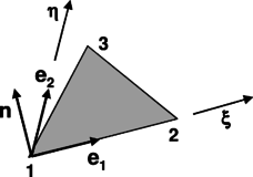
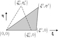
A triangular element composed by three corner nodes , and is defined according to Figure 2. Given that large displacements are expected, the strain state of the element is easier to assess using a local corrotational frame than in the global reference system.
The three unit vectors along the local axes are obtained from
|
|
(32) |
Thus, any point of the triangle can now be identified by its two local coordinates (ξ,η) by
|
|
(33) |
As a linear triangle always remains flat, the problem is greatly simplified by analysing the stress state on the ξ-η plane.
The components of the strain tensor can now be determined easily using the gradients of the element shape functions
|
|
(34) |
Note that many of the displacements are zero by virtue of the definition of the coordinate system; however. Eq. (34) is still useful because it can be used with any virtual displacement field. The corresponding stresses are calculated assuming a plane stress state (an acceptable hypothesis for thin surface elements) and linear elastic isotropic behaviour. Hence,
|
|
(35) |
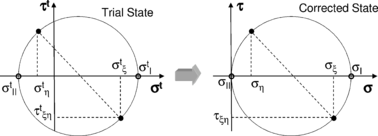
As the membrane buckles under compressive loads, the stresses given by Eq. (35) must be corrected to account for this fact. To this end we shall refer to Eq. (35) as the trial stress state . Then, three possible membrane states, depicted in Figure 4, are considered:
- Taut: the minimum principal trial stress is positive. No corrections are needed.
- Wrinkled: membrane is not taut, but the maximum principal strain is positive. Trial state is replaced with a uniaxial stress state.
- Slack: the maximum principal strain is negative. The corrected stresses are zero.
When the membrane is wrinkled the stress state must be corrected by (see Figure 5)
|
|
(36) |
The elastic stresses are next augmented with viscous terms to introduce a suitable level of numerical damping. Using the nodal velocities the components strain rate tensor can be computed. The damping stresses are then given by
|
|
(37) |
The total stress (elastic plus viscous) is then used to calculate the nodal forces using the change in energy due a virtual displacement of the nodes. As the triangular linear elements create a constant strain (and stress) field a single point Gauss quadrature is adequate to capture the effect of the virtual displacement
|
|
(38) |
with t being the element thickness and A0 its reference (undeformed) area.
When the element faces are subject to a pressure loading, the corresponding nodal generalized forces are obtained from Eq. (7). For the particular case of a uniform pressure acting on the upside element face (the side towards the normal vector points) the nodal forces are
|
|
(39) |
where stands for current projected area of the element. Finally, once all the components of the internal forces have been determined on the local reference frame, the global force vector can be assembled. The transformation to the global inertial reference system is performed through
|
|
(40) |
Finally, assuming uniform density, the mass matrices for the element are given by
|
|
(41) |
2.2 The aerodynamic model
In order to solve the aerodynamics of ram-air type parachutes a potential flow model is adopted assuming the fluid to be incompressible, inviscid and irrotational. The behaviour of this ideal fluid is described by the following Laplace’s equation
|
|
(42) |
where is a scalar function named velocity potential, defined in such a way that the flow velocity field results . The solution of Eq. (42) must be subject to proper boundary conditions; typically, a far-field condition and a kinematic condition on the body (Neumann condition) are required. The far-field condition requires that the flow disturbances disappear far away from the body. The Neumann condition specifies the normal component of the velocities across the body boundaries. Considering the parachute to be attached to a body fixed coordinate system () which moves in a steady inertial frame () according to a specified flight path, the Neumann condition can be expressed as
|
|
(43) |
where is the total velocity of a fluid particle, is the kinematic local velocity of the boundary, is the outward normal vector to the boundary and is a specified normal velocity relative to the boundary. The kinematic velocity in the inertial axes results , being the translational velocity of the body, the rates of rotation about the fixed axes, the position vector with respect to the body’s origin and a relative velocity accounting for deformations of the body. In spite of the fact that Eq. (42) along with far-field and Neumann conditions leads to a mathematically well-posed problem, the solution of lifting problems is not unique unless the circulation around the body is fixed. This is achieved by applying an additional condition known as Kutta condition. The latter determines the proper amount of circulation to be fixed and leads to ideal flow solutions in agreement with the real attached flow behaviour.
Next, the panel technique described by the authors in [5] is employed for solving the potential flow problem. The main characteristics of the methodology will be outlined next but further details can be found in the aforementioned work and the references cited therein.
2.2.1 A general solution procedure
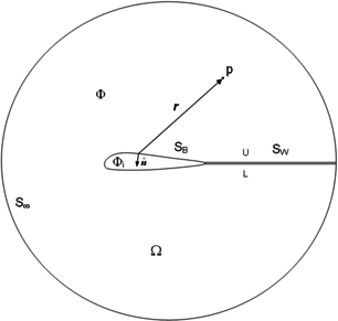
In order to solve the potential problem a low-order panel technique is applied. The problem setup consists of a parachute system immerse in an ideal fluid flow enclosed by far-field boundary . The parachute is defined by boundary and represents the upper (U) and lower (L) sides of a thin wake which extending downstream from the body (see Figure 6).
The boundaries divide the problem domain into external and internal regions having total velocity potentials and , both satisfying Eq. (42). By applying Green’s theorem [6], a general solution for the velocity potential at any point can be obtained
|
|
(44) |
where is the distance between the point and a surface element having normal vector pointing outside , is a constant freestream potential due to and no jump in the normal component of the velocity across the wake is considered (thin wake assumption). The terms and are the strength (per unit area) of doublet and source surface distribution. These represent, respectively, jumps in velocity potential and the normal component of the velocity across the boundaries. If the point lies on the integration surface (e.g. when evaluating the influence of a panel on itself), and Eq. (44) becomes singular. In such a case the point must be excluded from the integration and this procedure leads to when is inside the body. Note that the perturbation potential tends to zero when . Then, the far-field condition is automatically satisfied.
In order to solve Eq. (44), the internal Dirichlet condition is applied. Thus, considering the velocity potential at either region to consist of a freestream potential plus a perturbation potential due to the body and its wake , for a point inside the body Eq. (44) results
|
|
(45) |
where the doublet strength turns into the perturbation velocity potential and the source strength results . The solution of Eq. (45) reduces to find a suitable distribution of doublets and sources along the body. With this purpose, an arbitrary choice is made for considering the Neumann condition (43). This leads to
|
|
(46) |
and Eq. (45) can now be solved for the unknown body doublet distribution assuming the wake doublicity is determined (this is achieved by means of the Kutta condition).
Certain component parts of the parachutes which are very thin (e.g. stabilizer panels) cannot be regarded as enclosing an internal volume and the application of Eq. (45) could lead to numerical misbehaviours. An equation for modeling thin boundaries can be obtained at a given point by replacing the perturbation velocity, obtained by differentiating Eq. (44), into the Neumann condition. This yields
|
|
(47) |
which can be solved for the doublet distribution on thin aerodynamic surfaces. Given the fact that no jump in the normal component of the velocity is assumed across thin boundaries, the source contributions disappear from Eq. (47). However, if aerodynamic configurations having mixed thin/thick surfaces are considered, the contribution to the normal component of the velocity due to the source distribution on thick boundaries must be accounted for.
A discrete form of the governing equations (45) and (47) is achieved by breaking down the surface integrals into integrals over quadrilateral or triangular flat panels distributed along the body and the wake. Then, the discrete equations are satisfied at each panel on the body by considering all panels contributions . Accordingly, the discrete version of Eq. (45) is set at each control point on thick boundaries by
|
|
(48) |
where CJK and BJK denote the perturbation potential (per unit strength) due to a constant doublet and source distribution on panel K acting on a control point J. These influence coefficients are given by
|
|
(49) |
|
|
(50) |
and can be computed in a close manner in terms of the geometry of the panel and the coordinates of the point where the influence is sought. Similarly, Eq. (47) is discretized for each control point on thin surfaces as
|
|
(51) |
The normal components of the perturbation velocity at control point J due to a constant doublet and source distribution (per unit strength) on panel K are
|
|
(52) |
|
|
(53) |
with
|
|
(54) |
|
|
(55) |
Note that the source contribution given by is included in the discrete Eq. (51) to account for the perturbation velocity induced on thin panels by source distributions placed on thick panels (for configurations presenting mixed thin/thick boundaries).
2.2.2 Wake modeling
The time-steeping procedure presented in [6, 7] is adopted for modeling the wake. In this manner, non-linearities in the problem solution are avoided and the wake develops according to the motion of the body during the simulation. In order to determine the doublicity of the first row of panels shed into the wake, the Kutta condition is applied. Consequently, zero total vorticity at each spanwise station along the trailing edge is enforced by setting
|
|
(56) |
where and are the doublet strength at the upper and lower surfaces of the trailing edge and is the wake doublet strength next to the trailing edge. Eq. (56) allows the strengths of the shed panels to be written in terms of the body doublets and the linear system resulting from Eqs. (48) and (51) can be solved for the body doublets. Once the panels are shed its doublicity must remain constant to satisfy vorticity conservation. Consequently, these terms can be moved to the right hand side of the equations.
The wake shape is determined from the fact that no force can act on it, thus, the wake panels must be parallel to the local streamlines of the flow. In order to align a wake panel with the local flow (wake rollup), the induced velocities on the panel’s corner points are computed in the inertial frame and the coordinates of these points are displaced by . The induced velocity at each point is obtained by adding all the doublet and source panel contributions given by Eqs. (54) and (55) (note that the inertial frame is defined to be at rest).
2.2.3 Computation of the aerodynamic loads
The aerodynamic loads acting on the body are computed by means of the unsteady Bernoulli’s equation. Thus, the coefficient of pressure (Cp) can be calculated at any point as
|
|
(57) |
being the magnitude of the total velocity at the control point (kinematic + perturbation), the magnitude of a reference freestream velocity and the unsteady term .
For a surface panel belonging to thick boundaries, the tangential components of the perturbation velocity can be evaluated by taking the gradient of in panel coordinates. Hence,
|
|
(58) |
and the normal component of the velocity is given by
|
|
(59) |
being the panel’s source strength (46). Then, the total velocity on panel is obtained by adding the perturbation velocity to the instantaneous local kinematic velocity, i.e.
|
|
(60) |
Despite the fact that the evaluation of Eqs. (58) can be easily performed on structured discretizations by using finite difference approximations, a more general approach is needed for arbitrary body discretizations. In this work the derivatives are evaluated at each panel using the value of the doublet strength at the panel’s corner points . These are obtained by
|
|
(61) |
where and are the surface area and doublet strength of a panel ' respectively and the summation is performed over the panels surrounding a corner point . Once the doublet strengths at the panel’s corner points are determined, the derivatives (58) are evaluated (in panel coordinates) by using a standard finite element approximation.
A rather different procedure is needed when computing the aerodynamic loads acting on thin panels. In this case, the gradient of the doublet strength provides the jump in the tangential velocity across the panel, i.e.
|
|
(62) |
and the tangential components of the total velocity are obtained by
|
|
(63) |
being an averaged tangential velocity at the panel’s control point (kinematic + perturbation) which omits the panel contribution on itself. Therefore, the net pressure acting on the panel can be computed by replacing Eqs. (63) with (62) in Eq. (57). This results
|
|
(64) |
Suspension lines and internal flow treatment
In addition to the aerodynamic loads on the parachute canopy and stabilizer panels, wind loads are applied to the suspension and control lines. These loads are computed in a simplified manner by considering the cords as long cylinders exposed to the wind. In this way, experimental drag coefficients can be applied and the aerodynamic force is computed taking into account the magnitude of the local dynamic pressure and the direction of the total velocity vector acting on the cable elements.
Given the fact that the parachute internal flow is not resolved in this work, a constant stagnation pressure is applied inside the canopy to pressurize the cells. As regards parachute air intake, note that it should be panelized to close the canopy under study (as required by the aerodynamic model employed) but no aerodynamic loads are computed on these panels. Furthermore, as the presence of air intake panels may cause disruption of the structural behaviour of the canopy, the former are assumed to be made of a material having a relative small thickness, Young module and density, in such a way that the panels capability to withstand loads is negligible in relation to the rest of canopy panels.
2.3 Coupling the aerodynamic and structural modules
A 2-way coupling between the aerodynamic (A) and structural (S) solvers is adopted in the parachute simulation code and the A/S models share the same mesh. Due to the fact that the aerodynamic mesh can be composed by quadrilateral or triangular elements, when a quadrilateral element is passed to the structural solver, it is internally transformed into a pair of triangles in order to carry out the analysis. As the stability limit of the explicit structural solver is small, several structural iterations are performed for each aerodynamic time step and the convergence to the steady state regime can be accelerated by using an under-relaxation technique when transferring aerodynamic loads to the structure. For long-term response analysis (e.g. trajectory analysis) the number of structural steps can be reduced by approximating the behaviour of the membrane as quasi-static (i.e. considering only discrete states of equilibrium along the flight path).
3. PROGRAM USER INTERFACE
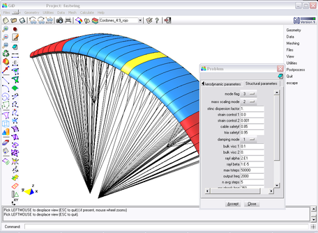
The use of the parachute simulation code is facilitated by a graphical user interface2 (GUI) developed on the basis of the GiD system [8], an in-house software providing fully integrated tools for geometry and input data definition, code execution and post-processing of the analysis results. The GiD pre-process module allows generating all the input data for the simulation. Complex CAD geometries can be created and manipulated in a simple and efficient manner and models can be also imported on IGES, DXF and many other typical formats. The application of boundary conditions and the definition of the simulation parameters can be easily carried out through a series of customized menus which also allow verifying the conditions prescribed on the model. A view of the user interface in pre-process mode is displayed in Figure 7. In addition, GiD includes all the necessary tools for generating structured and non-structured meshes in complex geometries. After creating the mesh, all the code input files are automatically generated by specific customized templates. Then, the simulation can be started and the evolution of the process followed into the GiD enviroment. As soon as results are available, these can be visualized by switching to the GiD post-process module. This tool offers a wide range of possibilities, not only for visualization purposes but also for results data extraction including text and binary files, user-defined plots, images and video animations showing the simulation evolution in time.
4. NUMERICAL APPLICATIONS
Three test cases are presented next with the aim of showing the performance of the present methodology. The first example concerns a stationary analysis of a ram-air parachute in which the flight equilibrium angle is sought. The second one involves a non-stationary manoeuvre simulation and, finally, the third test case presents a preliminary analysis of the deployment and inflation of a conventional circular parachute. All the examples presented give an idea of the potential the proposed techniques have for analyzing parachute problems.
4.1 Stationary analysis of a large ram-air parachute
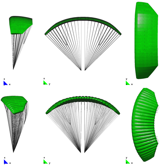
Steady aerodynamic characteristics of a large ram-air parachute are investigated in this example and the results are compared with experimental measurements given in [9]. The model is a high glide-performance parachute aimed at delivering very heavy payloads designed and manufactured by CIMSA in the framework of the FASTWing Project [10]. The model canopy discretization consists of an unstructured distribution of 11760 triangular elements (8824 for the aerodynamic surfaces exposed to the wind and 2936 for the internal ribs) and 11912 cable elements model the suspension and control lines and reinforcements integrated into the canopy. The freestream velocity is set to 23 m/s and the simulation is initialized with a partially inflated parachute configuration. The movement of the suspension line’s confluence points is restricted to follow the experimental setup. To obtain a faster convergence to the equilibrium position of the parachute, some degree of under-relaxation is employed when transferring the aerodynamic loads to the structure. Moreover, a simplified wake model with a limited roll-up is adopted to reduce non-linear effects in the aerodynamic problem solution. After some time steps the parachute achieves its equilibrium position according to the rigging angle established by the model geometry. Initial and equilibrium parachute configurations are shown in Figure 8.
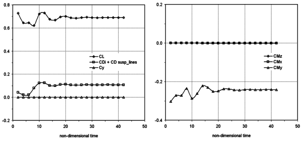
The time history of force and moment coefficients is displayed in Figure 9, where the moment coefficients are computed about a point located between the suspension line’s confluence points. Note that the transient behaviour lacks a physical meaning as under-relaxation has been employed to accelerate the problem convergence to the steady state solution.
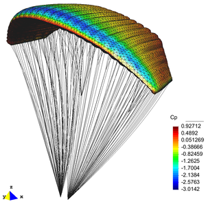
Considering the equilibrium lift and drag coefficients displayed in Figure 9, a numerical angle of descent can be estimated. Experimental measurements report stationary lift and drag coefficients and , which yield a descent angle . Taking into account the characteristics of the aerodynamic model employed in this work, numerical results are quite consistent with experimental ones. The differences could be explained by two main factors. First, the potential flow model could overestimate lift as the entire flow around the canopy is considered to be attached and, second, viscous contributions to the drag coefficient are not accounted for in this simulation. It should be noticed that important discrepancies could arise in the equilibrium conditions due to drag variations, particularly for low lift values. In this sense, semi-empirical models for canopy drag estimation could be employed to improve the accuracy of the numerical model. Moreover, coupled boundary layer-potential approaches could be suitable in certain analysis, though these two possibilities should be investigated further. Next, Figure 10 shows Cp distribution computed over the parachute for the equilibrium condition.
4.2 Parachute manoeuvre analysis
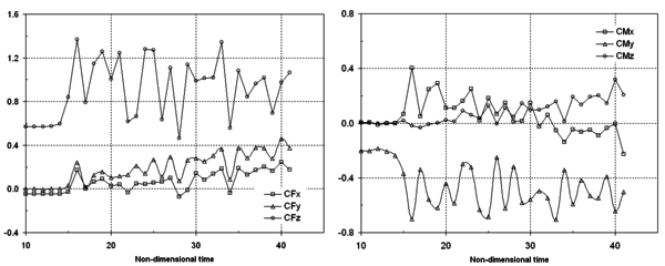
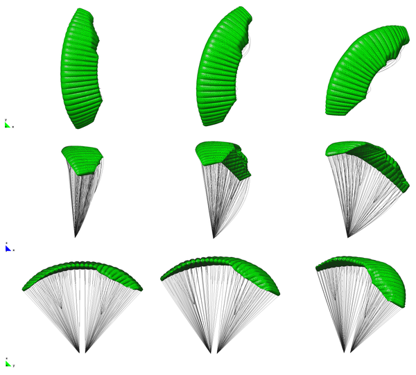
The parachute studied in the previous test case is induced to initiate a skid steering right-turn by applying a 2.2 m downward deflection to the right brake lines. The freestream velocity is set to 23 m/s and the simulation starts with a partially inflated parachute configuration. Once the equilibrium flight conditions are achieved, the turn manoeuvre is induced by pulling the right control lines. The simulation is stopped some time units after the turn is established because the parachute support mechanism employed is not intended for a full turn simulation. The time evolution of aerodynamic force and moment coefficients during the manoeuvre is presented in Figure 11 and some snapshots of the configuration taken at different instant times are shown in Figure 12. In spite of the fact that no experimental data is available for this test case, the numerical results match those observed in real behaviour of ram-air parachutes performing similar manoeuvres.
As regards manoeuvre simulation, it should be noticed that at present different supporting systems intended to obtain parachute static and dynamic characteristics (as the parachute was mounted on a wind tunnel) are being evaluated. In addition, the structural analysis module has been recently enhanced to allow simulating the payload attached to the parachute, being the complete parachute-payload system subject to gravitational forces. This avoids the need to restrain the movements of the parachute’s confluence points and allows simulating specific flight conditions in detail and completing trajectory analyses with higher reliability.
4.3 Inflation process of a conventional parachute
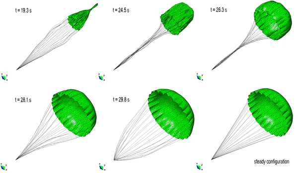
This is a simple inflation test aimed at exploring the capabilities of the computational code to simulate parachute deployment and inflation. The model proposed for the aerodynamic loads is quite simple. The parachute is initially deployed by applying a force at the canopy apex in the direction of the incident wind. The inflation stage, which begins after line and canopy stretching, occurs due to a variable pressure force applied on the canopy accounting for relative wind direction and velocity. In this way, the maximum pressure force corresponds to the fluid stagnation condition and that value is decreased according to the orientation of the elements in relation to the incident wind. The parachute is discretized by an unstructured distribution of 3390 triangular elements and 2040 cable elements modeling the suspension lines and the fabric reinforcements. The canopy has a surface area and the relation between the latter and the projected area is . The airstream velocity is set to . Some snapshots of the parachute at different instant times during the inflation process are presented in Figure 13.
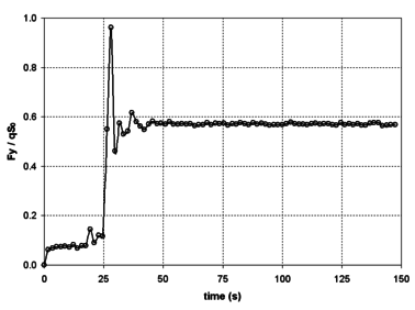
The reaction force computed at the confluence point during the inflation process is shown in Figure 14. There, a satisfactory agreement with experimental results reported in [11] for similar configurations is observed.
Future developments in parachute deployment and inflation simulation are to be focused on evaluating the feasibility of more-accurate semi-empirical models such as filling distance, kinetics and momentum methods. These inflation theories can be implemented with a low computational cost and have been applied to a wide range of problems with satisfactory results; see [12] for a review.
5. COMPLEMENTARY TOOLS: TRAJECTORY AND CONTROL ANALYSIS
The development of a set of tools aimed at an integral study of the flight performance of a parachute-payload system, its trajectory dynamics and guidance control systems effects is undertaken with the objective of assisting the design, analysis and evaluation of guided parafoil systems3. In the 6-DoF model proposed, the dynamic model of the parachute is characterized by aerodynamic, mass and inertial properties which can be obtained from experimental and numerical sources. Provided these characteristics, the model allows predicting the behaviour of the parachute system subject to different flight and environmental conditions with a very low computational cost. The aerodynamic data characterizing the parachute is to be obtained with the computational code described in Section 2. A suitable evaluation strategy intended to this aim is currently under development taking into consideration the experimental setups presented in [13, 14]. The autonomous guidance, navigation and control system (GNC) is implemented by means of a proportional-integral-derivative (PID) algorithm, similar to Unmanned Aerial Vehicles (UAV) autopilot systems. Future implementations will include Monte Carlo simulations, parameter identification for flight-test data reduction and an advanced GUI. Next, a brief description of the dynamic 6 DoF model and a preliminary implementation of control strategies are presented. By the end of this section, two numerical results illustrate the performance of the proposed methodologies.
(2) The user interface has been developed at Terrassa CIMNE classroom (CIMNE-ETSEIAT).
(3) This work is being developed at the Instituto Universitario Aeronáutico CIMNE classroom (CIMNE-IUA).
5.1 The parachute dynamic model
The parachute dynamic model adopted in this work is based on that developed by Slegers and Costello [15]. Its main characteristics can be summarized as follows
- 6 DoF aerodynamic model based on derivatives
- Apparent mass model based on Barrows [16]
- Independent left/right brake input for lateral control
- Variable incidence angle for longitudinal control (glide slope)
- Automatic control for precision placement
- Standard atmosphere and wind input capability
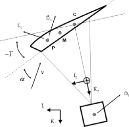
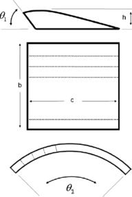
Figure 15 sketches the parachute-payload configuration analyzed. With the exception of movable brakes, the canopy is considered to have a fixed shape after being completely inflated. The combined system of the parachute canopy and the payload are modeled with 6 DoF, including three inertial position components of the total system mass center as well as the three Euler orientation angles. Orientation of the canopy with respect to the payload is defined by the incidence angle Γ and is considered a control variable. Rotation of the canopy about point C allows the tilting of the canopy lift and drag vectors, causing changes in the equilibrium glide slope.
The kinematic equations for the parachute-payload system are given by
|
|
(65) |
where , , , is the transformation matrix from the inertial reference frame to the body reference frame, are the Euler roll, pitch and yaw angles and are the angular velocities in a body reference frame.
|
|
(66) |
The dynamic equations are obtained by summing forces and moments about the system CG (in the body reference frame) and equating to the time derivative of linear and angular momentum respectively, i.e.
|
|
(67) |
where the indices and denote weight, aerodynamic, payload and apparent mass respectively. are cross-product matrices of vector expressed in the reference frame, is the total system inertia matrix and and stand for aerodynamic forces and moments. These terms are calculated by adding contributions of the different aerodynamic derivatives of the system [15]. The apparent mass forces and moments are computed according to the model developed by Barrows [16].
5.2 Lateral Track Control Strategy
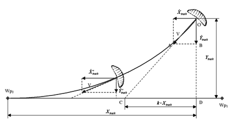
A heading tracking control strategy is implemented following the PID navigation system presented in [17] with the aim of guiding the parachute from a waypoint (parachute deployment) to a specified target waypoint through a yaw-rate command (see Figure 16).
The control strategy proceeds as follows. For a given parachute track position , measured from , the vehicle ground velocity vector is pointed in the direction of a line intercepting the track at point . The interception point is determined by considering that the distance on the track line from this point to is, at any instant time, equal to , being a design parameter. From the geometry of the similar triangles and , the parachute position and velocity is established according to
|
|
(68) |
Accordingly, an error E is defined by
|
|
(69) |
and this equation is satisfied using a proportional feedback control law. In other words, if Eq. (69) is not satisfied (there is a heading error), the error ![]() commands the yaw-rate control input by giving it an input of desired yaw-rate as,
commands the yaw-rate control input by giving it an input of desired yaw-rate as,
|
|
(70) |
where the proportional gain is determined iteratively in order to achieve good tracking without overshoots and the yaw-rate command is limited to with the aim of avoiding numerical misbehaviours. Then, the desired yaw-rate is compared to the actual yaw-rate and left or right brake are applied according to
|
|
(71) |
being a gain parameter accounting for the kinematics of the parachute brake.
5.3 Application examples
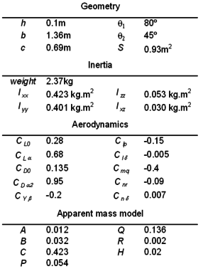
Two simulation cases involving a small ram-air parachute, subject to different flight conditions, are intended to show the performance of the dynamic model and the lateral control strategy. The geometrical, mass, inertial and aerodynamic characteristics4 of the test parachute-payload system are presented in Table 1.
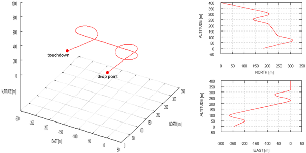
Test case 1: glide slope (GS) control systems are studied in this example along with standard brake inputs for different wind settings. The parachute-payload system is deployed from a 400 m altitude with heading north, fixed incidence angle and no wind. The computed trajectory is presented in Figure 17, where left and right brake inputs are applied.
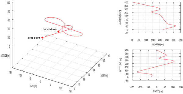
Next, the same simulation is performed, but this time applying a 3 m/s wind coming from East. The computed results are displayed in Figure 18.
Test case 2: in this example the parachute-payload system is guided when following a flight path between two specified waypoints and . The starting position and heading of the vehicle is shown with the parachute top-view in Figure 19. There, several flight paths computed for different values of parameter and heading angles are shown. This test case reveals the potential these set of tools have for studying GNC strategies.
(4) Data provided by Prof. Costello from Georgia Tech in personal communication to the authors.
6. CONCLUSIONS
The role parachutes have in many civil, humanitarian and military applications call for new and improved computational tools aimed at tackling the current lack of software applications in the field. New developments carried out at CIMNE to this end have been presented in this work. These developments involve a coupled fluid-structural solver intended for the unsteady simulation of ram-air type parachutes and a set of complementary tools aimed at studying trajectory and control systems effects. The coupled solution approach, based on an unsteady low-order panel method for aerodynamics, in conjunction with an explicit dynamic FE solver for the structure, has succeeded in solving ram-air parachute problems. This finding has been supported by the numerical examples presented and other many simulations performed to date. In addition, though at a preliminary stage, the complementary tools intended for trajectory and control effects analyses have shown their potential for the design, analysis and evaluation of guided parachute systems. The robustness and efficiency of the new coupled fluid-structural code have been highly improved with respect to the previous developments, at the same time that the scope of its potential applications has been widely extended. As it has been highlighted throughout this work, the challenges involved in the numerical simulation of parachutes are not minor; however, the numerical results obtained to date encourage us to go further in the development of numerical tools which are currently necessary as well as important contributions to the analysis and evaluation of parachute systems.
7. FUTURE LINES OF INVESTIGATION
The future lines of research intended for the development of new and enhanced implementations in the field of numerical simulation of parachutes are described next.
From the point of view of the structural code, the modeling of anisotropic materials taking into account the directional nature of the fabric is planned for the near future. In addition, sliding cables and a contact model are required for a proper simulation of parachute deployment and inflation. This needs the slider assisted reefing process during parachute inflation to be correctly modeled. Thus, a special type of kinematic constraint must be implemented in which a mesh node is forced to lie on a cable element, but the constrained node need not to coincide with the nodes of the cable. This is a complex problem which was not properly resolved in former developments and requires further investigation. Moreover, a contact model must be incorporated into the solver to reproduce the parachute deployment sequence. This shall prevent the fabric surface from intersecting itself, thus yielding non-physical behaviour. An efficient way of implementing the reefing and contact models must also be investigated in order to keep the good performance of the structural solver.
As long as aerodynamics is concerned, the adopted panel technique has limitations in the treatment of manoeuvres involving large deformations and the simulation of round-type conventional parachutes. Partially inflated canopy configurations are usually found during the flight, another situation which the present model cannot simulate accurately. Consequently, new approaches should be evaluated taking always computational efficiency as a priority variable. In this sense, boundary methods could even be applied and certain techniques, such as vortex methods, are promising as they can manage a wide range of parachute configurations and flight conditions with low computation cost, even when massive flow separation must be considered (e.g [18]).
In relation to parachute deployment and inflation, at present the software allows specified constant or time varying pressure forces to be applied on the canopy and suspension lines for an approximate simulation of these processes. In order to address the complexity of the flow behaviour in these situations, at a first stage it is planned to investigate the application of semi-empirical deployment and inflation models such as filling distance, kinetics and momentum methods, which have been extensively applied with quite satisfactory results [12].
Finally, the tool package for trajectory and control analysis is being expanded. Current efforts are focused on designing a procedure for estimating parachute aerodynamic parameters based on the coupled fluid-structural code implemented. Future developments will include standard/customizable PID control strategies, Monte-Carlo simulations for sensitivity analysis and a parameter estimation technique for flight test data reduction.
REFERENCES
[1] Guerra, A. Development and validation of a numerical code for analyzing parachutes. Undergraduated thesis presented at the Scola Tecnica Superior d'Enginyers Industrial i Aeronàutica de Terrassa, Technical University of Catalonia (in Spanish). 2009.
[2] PARACIMSA. New simulation tools for parachute design improvements. REF. CIT-020400-2005-30. Programa PROFIT, Ministerio de Educación y Ciencia, 01/01/2005 - 31/12/2005.
[3] CIMSA Ingeniería en Sistemas. Web page: http://www.cimsa.com/ (22 March 2010).
[4] Flores, R., Ortega, E., and Oñate, E. Explicit dynamic analysis of thin membrane structures. CIMNE publication, 2010.
[5] Ortega, E., Flores, R., and Oñate, E. A 3D low-order panel method for unsteady aerodynamic problems. CIMNE publication, 2010.
[6] Katz, J. and Plotkin, A. Low-Speed aerodynamics. From wing theory to panel methods., McGraw-Hill, 1991.
[7] Ashby, D. L. Potential flow theory and operation guide for the panel code PMARC_14. NASA TM-1999-209582, 1999.
[8] GiD. The personal pre and post processor. Web page: http://www.gidhome.com (17 March 2010).
[9] Hollestelle, P. The FASTWing Project: Wind tunnel test - Realisation and results. 18th AIAA Aerodynamic Decelerator Systems Technology Conference and Seminar. AIAA paper 2005-1641, 2005.
[10] Benolol, S. and Zapirain, F. The fastwing project, parafoil development and manufacturing. 18th AIAA Aerodynamic Decelerator Systems Technology Conference and Seminar. AIAA paper 2005-1639, 2005.
[11] Scher, S. H. and Young, I. G. Drag coeficcients for partially inflated flat circular parachutes. NASA Technical Note D-6423, 1971.
[12] Cockrell, D. J. The aerodynamics of parachutes. AGARDograph Nº 295. AGARD-AG-295, 1987.
[13] Burk, S. M. and Ware, G. M. Static Aerodynamic Characteristics of Three Ram-Air Inflated Low Aspect Ratio Fabric Wings. NASA Report, NASA-TN-D-4182, 1967.
[14] Ware, G. M. and Hassell, J. L. J. Wind-Tunnel Investigation of Ram-Air-Inflated All-Flexible Wings of Aspect Ratios 1.0 to 3.0. NASA Report, NASA-TM-SX-1923, 1969.
[15] Slegers, N. and Costello, M. Use of variable incidence angle for glide slope control of autonomous parafoils. Journal of Guidance, Control and Dynamics, 31: 585-596, 2008.
[16] Barrows, T. Apparent mass of parafoils with spanwise camber. AIAA Paper 2001-2006, 2001.
[17] Nicolescu, M. Lateral tack control law for aerosonde UAV. AIAA Paper 2001-0016, 2001.
[18] Strickland, J. H., Homicz, G. F., Porter, V. L., and Gossler, A. A. A 3-D vortex code for parachute flow predictions: version 1.0. Sandia National Laboratories, Report SAND2002-2174, 2002.
Document information
Published on 01/01/2010
Licence: CC BY-NC-SA license
Share this document
Keywords
claim authorship
Are you one of the authors of this document?

