Abstract
We present a general formulation for incompressible fluid flow analysis using the finite element method (FEM) and a lagrangian description. The necessary stabilization for dealing with the incompressibility condition is introduced via the so called finite calculus (FIC) method. Both a quasi-implicit algorithm and a fractional step scheme are described. Examples of application of the lagrangian flow description are presented.
Keywords: Lagrangian formulation, incompressible fluid flow, finite calculus, finite element method.
1 INTRODUCTION
The development of efficient and robust numerical methods such as the finite element, finite volume and finite difference methods for analysis of incompressible flows has been a subject of intensive research in last decades [1,2]. Much effort has been spent in developing the so called stabilized numerical methods overcoming the two main sources of instability in incompressible flow analysis, namely those originated by the high values of the convective terms and those induced by the difficulty in satisfying the incompressibility conditions.
The problems originated by the convective terms dissapear if a lagrangian description is used. In the lagrangian formulation the motion of each individual flow particle is followed as in solid mechanics problems. The difficulty is tranferred now to the problem if adequately moving the mesh nodes. Indeed for large mesh motions remeshing is necessary after flow time steps.
A popular way to overcome the problems with the incompressibility constraint is by introducing a pseudo-compressibility in the flow and using implicit and explicit algorithms developed for this kind of problems such as pressure segregation schemes [3], artificial compressibility methods [4-6] and preconditioning techniques [7]. Other FEM schemes with good stabilization properties for the incompressibility terms are based in Petrov-Galerkin (PG) techniques. The background of PG methods are the non-centred (upwind) schemes for computing the first derivatives of the convective operator in FD and FV methods [2,8]. More recently a general class of Galerkin FEM has been developed where the standard Galerkin variational form is extended with adequate residual-based terms in order to achieve a stabilized numerical scheme. Among the many methods of this kind we can name the Streamline Upwind Petrov Galerkin (SUPG) method [1,9-18] the Galerkin Least Square (GLS) method [19,20], the Taylor-Galerkin method [21], the Characteristic Galerkin method [22-24] and its variant the Characteristic Based Split (CBS) method [25,26] the pressure gradient operator technique [27] and the Subgrid Scale (SS) method [28-30]. A good review of these methods can be found in [31].
In this paper a stabilized finite element formulation for incompressible lagrangian flows is derived in a different manner. The starting point are the modified governing differential equations of the fluid flow problem formulated via a finite calculus (FIC) approach [32]. The FIC method is based in invoking the balance of fluxes in a fluid domain of finite size. This introduces naturally additional terms in the classical differential equations of infinitesimal fluid mechanics which are a function of the balance domain dimensions. The new terms in the modified governing equations provide the necessary stabilization to the discrete equations obtained via the standard Galerkin finite element method [33-39].
The layout of the chapter is the following. In the next section, the main concepts of the FIC approach are introduced via a simple 1D convection-diffusion model problem. Then the basic FIC equations for incompressible lagrangian flow problems are presented. The finite element discretization is introduced and the resulting matrix formulation is detailed. Both monolithic and fractional step schemes for the transient solution are presented.
The lagrangian description has many advantages for tracking the displacement of fluid particles in flows where large motions of the fluid surface occur such in the case of breaking waves, splashing of water, filling of moulds, etc. As above mentioned, the positive feature of the lagrangian formulation is that the convective terms dissapear in the governing equations of the fluid flow; in return the updating of the mesh at almost every time step is now a necessity and an efficient algorithm for generation of a finite element mesh must be used.
The examples show the efficiency of the lagrangian formulation to solve fluid flow problems involving contact with moving solids, surface waves around ships and large motions of the free surface, among others.
2 THE FINITE CALCULUS METHOD
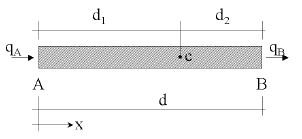
We will consider a convection-diffusion problem in a 1D domain of length . The equation of balance of fluxes in a subdomain of size belonging to (Figure 1) is written as
|
|
(1) |
where and are the incoming and outgoing fluxes at points and , respectively. The flux includes both convective and diffusive terms; i.e. , where is the transported variable, is the velocity and is the diffusitivity of the material.
|
| Figure 1: Equilibrium of fluxes in a balance domain of finite size |
Let us express now the fluxes and in terms of the flux at an arbitrary point within the balance domain (Figure 1). Expanding and in Taylor series around point up to second order terms gives
|
|
(2) |
Substituting eq.(2) into eq.(1) gives after simplification
|
|
(3) |
where and all derivatives are computed at point .
Standard calculus theory assumes that the domain is of infinitesimal size and the resulting balance equation is simply . We will relax this assumption and allow the balance domain to have a finite size. The new balance equation (3) incorporates now the underlined term which introduces the characteristic length . Obviously, accounting for higher order terms in eq.(2) would lead to new terms in eq.(3) involving higher powers of .
Distance in eq.(3) can be interpreted as a free parameter depending, of course, on the location of point (note that ). However, the fact that eq.(3) is the exact balance equation (up to second order terms) for any 1D domain of finite size and that the position of point is arbitrary, can be used to derive numerical schemes with enhanced properties simply by computing the characteristic length parameter from an adequate “optimality” rule.
Equation (3) can be extended to account for source effects. The full stabilized equation can be then written in compact form as
|
|
(4) |
with
|
|
(5) |
where is the external source. For consistency a “finite” form of the Neumann boundary condition should be used. This can be readily obtained by invoking balance of fluxes in a domain of finite size next to the boundary where the external (diffusive) flux is prescribed to a value . The modified Neumann boundary condition can be written as [32]
|
|
(6) |
The definition of the problem is completed with the standard Dirichlet condition prescribing the value of at the boundary .
The underlined terms in Eqs.(5) and (7) introduce the necessary stabilization in the discrete solution of the problem using whatever numerical scheme. For details see [32-41].
The starting point in the next section are the FIC equation for a viscous incompressible fluid written in a lagrangian frame of reference.
3 FIC EQUATIONS FOR VISCOUS INCOMPRESSIBLE FLOW USING A LAGRANGIAN DESCRIPTION
The FIC governing equations for a viscous incompressible fluid can be written in a lagrangian frame as
Momentum
|
|
(7) |
Mass balance
|
|
(8) |
where
|
|
(9) |
|
|
(10) |
Above is the velocity along the ith global axis, is the (constant) density of the fluid, is the absolute pressure (defined positive in compression), are the body forces and are the viscous deviatoric stresses related to the viscosity by the standard expression
|
|
(11) |
where is the Kronecker delta and the strain rates are
|
|
(12) |
The FIC boundary conditions are
|
|
(13) |
|
|
(14) |
and the initial condition is for .
In Eqs.(13) and (14) and are surface tractions and prescribed displacements on the boundaries and , respectively, are the components of the unit normal vector to the boundary and are the total stresses given by . The sign in front the stabilization term in Eq.(13) is positive due to the definition of in Eq.(9).
The in above equations are characteristic lengths of the domain where balance of momentum and mass is enforced. In Eq.(13) these lengths define the domain where equilibrium of boundary tractions is established [32].
Eqs.(7)–(14) are the starting point for deriving stabilized finite element methods for solving the incompressible Navier-Stokes equations in a lagrangian frame of reference using equal order interpolation for the velocity and pressure variables [37-39]. Application of the FIC formulations to meshless analysis of fluid flow problems using the finite point method can be found in [40,41].
3.1 Stabilized integral forms
From Eq.(7) it can be obtained (taking into account Eqs.(9) and (11))
|
|
(15) |
where
|
|
(16.a) |
and
|
|
(16.b) |
Substituting Eq.(15) into Eq.(8) and retaining the terms involving the derivatives of with respect to only, leads to the following expression for the stabilized mass balance equation
|
|
(17) |
with
|
|
(18) |
The 's in Eq.(17) are termed in the stabilization literature intrinsic time parameters. Similar values for (usually is taken) are used in other works from ad-hoc extensions of the 1D advective-diffusive problem [12-31]. It is remarkable that the intrinsic time parameters have been deduced here from the general FIC formulation and this shows the possibilities of the method.
The weighted residual form of the momentum and mass balance equations (Eqs.(7) and (17)) is written as
Momentum
|
|
(19) |
Mass balance
|
|
(20) |
where and are arbitrary weighting functions representing virtual velocity and virtual pressure fields. Integration by parts of the terms leads to
|
|
(21.a) |
|
|
(21.b) |
The third integral in Eq.(21.a) is expressed as a sum of the element contributions to allow for discontinuities in the derivatives of along the element interfaces.
Also in Eq.(21.a) we will neglect hereonwards the third integral by assuming that is negligible on the boundaries. The deviatoric stresses and the pressure terms in the first integral of Eq.(21.a) are integrated by parts in the usual manner. The resulting equations are
Momentum
|
|
(22) |
Mass balance
|
|
(23) |
We note that in Eq.(22) we use now the standard form of the convective operator for incompressible flows (i.e. neglecting the contribution from the volumetric strain rate ). Also in Eq.(22)
|
|
3.2 Convective and pressure gradient projections
The computation of the residual terms can be simplified if we introduce now the pressure gradient projections , defined as
|
|
(24) |
We can express in Eq.(23) in terms of the which then become additional variables. The system of integral equations is now augmented in the necessary number of additional equations by imposing that the residual vanishes (in average sense) for the form given by Eq.(24). This gives the final system of governing equation as:
|
|
(25) |
|
|
(26) |
|
|
(27) |
with . In Eqs.(27) are appropriate weighting functions and the weights are introduced for convenience.
4 FINITE ELEMENT DISCRETIZATION
We choose continuous linear interpolations of the velocities, the pressure and the pressure gradient projections over three node triangles (2D) and four node tetrahedra (3D). The linear interpolations are written as
|
|
(28) |
where (4) for triangles (tetrahedra), denotes nodal variables and are the linear shape functions [1].
Substituting the approximations (28) into Eqs.(25–27) and choosing the Galerking form with leads to following system of discretized equations
|
|
(29.a) |
|
|
(29.b) |
|
|
(29.c) |
where the element contributions are given by (for 2D problems)
|
|
(30) |
with and .
In above is the standard strain rate matrix and the deviatoric constitutive matrix (assuming ). For 2D problems
|
|
(31) |
The steady-state form of Eqs.(29) can be expressed in matrix form as
|
|
(32) |
The system is symmetric and always positive definite and therefore leads to a non singular solution. We note that this property holds for any interpolation function chosen for and , therefore overcoming the Babuŝka-Brezzi (BB) restrictions [1].
A reduced velocity-pressure formulation can be obtained by eliminating the pressure gradient projection variables from the last equation to give
|
|
(33) |
The reduction process is simplified by using a diagonal form of matrix . Obviously above reduction is also applicable to the transient case.
4.1 Quasi-implicit scheme
The solution process can be advanced in time in a (quasi-nearly) implicit iterative manner using the following scheme.
Step 1
|
|
(34) |
Step 2
|
|
(35) |
Step 3
|
|
(36) |
where .
Steps 1–3 are repeated until converged values of the velocities, the pressure and the pressure gradient projection variables is obtained. The process within a time step increment is completed with steps 4 and 5 described below.
Step 4
Update the mesh nodes in a lagrangian manner as
|
|
(37) |
Step 5
Generate a new mesh. This can be effectively performed using the procedure described in Section 5. Indeed the mesh regeneration can take place after a prescribed number of time steps or when the nodal displacements induce significant distorsions in some element shapes.
Details of the treatment of the boundary conditions in the lagrangian flow formulation can be found in [51,52].
Some practical remarks
In Eqs.(34–36) denote nodal values at the th time step and the ith iteration. Note that etc. Also for the computations in step 1 at the onset of the iterations.
Steps 1 and 3 can be solved explicitely by choosing a lumped (diagonal) form of matrices and . In this manner the main computational cost is the solution of step 2 involving the inverse of a Laplacian matrix. This can be solved very effectively using an iterative method such as the conjugate gradient method or similar.
For the iterative proces is unavoidable. The iterations follow until convergence is reached in an adequate error norm in terms of the velocity and pressure variables, or the residuals and . Indeed some ot the 's in Eqs.(34)–(36) can be made equal to zero. Note that for the algorithm is unconditionally unstable. A particularity interesting and simple semi-implicit form is obtained by making . Now all steps can be solved explicitely with exception of Step 2 for the pressure, which still requires the solution of a simultaneous system of equations.
Convergence of this solution scheme is however difficult for some problems. An enhanced version of the algorithm can be obtained by simply adding the term where to the equation for the computation of the pressure in the second step. The new term acts as a preconditioner of the pressure equation given now by
|
|
(38) |
Note that the added term vanishes for the converged solution (i.e. when ).
An alternative to above algorithm is to use the fractional step method described in the nex section.
4.2 Fractional step method
An effective algorithm can be obtained by splitting the pressure from the momentum equations as follows
|
|
(39.a) |
|
|
(39.b) |
In Eq.(39.a) is a variable taking values equal to zero or one. For , and for , . Note that in both cases the sum of Eqs.(39.a) and (39.b) gives the time discretization of the momentum equations with the pressures computed at . The value of from Eq.(39.b) is substituted now into Eq.(29.b) to give
|
|
(40.a) |
The product can be approximated by a laplacian matrix, i.e.
|
|
(40.b) |
A semi-implicit algorithm can thus be derived as follows.
Step 1 Compute explicitely from Eq.(39.a) with where subscript denotes hereonwards a diagonal matrix.
Step 2 Compute and from Eq.(40.a) as
|
|
(41.a) |
|
|
(41.b) |
Step 3 Compute explicitely from Eq.(39.b) with
Step 4 Compute explicitely from Eq.(36) as
|
|
(42) |
Steps 5 and 6 coincide with steps 4 and 5 of Section 4.1.
This algorithm has an additional step than the iterative scheme of Section 4.1. The advantage is that now Steps 1 and 2 can be fully linearized by choosing . Also the equation for the pressure variables in Step 2 has improved stabilization properties due to the additional laplacian matrix .
The boundary conditions are applied as follows. No condition is applied in the computation of the fractional velocities in Eq.(39.a). The prescribed velocities at the boundary are applied when solving for in step 3. The prescribed pressures at the boundary are imposed by making zero the pressure increments at the relevant boundary nodes and making equal to the prescribed pressure values.
5 GENERATION OF A NEW MESH
One of the key points for success of the lagrangian flow formulation here described is the fast regeneration of a mesh at every time step on the basis of the position of the nodes in the space domain. In our work the mesh is generated using the so called extended Delaunay tesselation (EDT) presented in [44,47]. The EDT allows to generate meshes of elements with arbitrary polyhedrical shapes (combining triangles, quadrilaterals and other polygons in 2D and tetrahedra, hexahedra and arbitrary polyhedra in 3D) in a computing time of order , being the total number of nodes in the mesh. The shape functions of the elements can be simply obtained using the so called non-sibsonian interpolations. Details of the mesh generation procedure can be found in [44-47].
Once the new mesh has been generated at each time step the numerical solution is found using the finite element algorithm described in the paper.
The combination of elements with different geometrical shapes in the same mesh is one of the innovative aspects of the lagrangian formulation presented here.
6 IDENTIFICATION OF BOUNDARY SURFACES
One of the main problems in mesh generation is the correct definition of the boundary domain. Sometimes, boundary nodes are explicitly defined as special nodes, which are different from internal nodes. In other cases, the total set of nodes is the only information available and the algorithm must recognize the boundary nodes. Such is the case in lagrangian flow methods in which, at each time step, new nodal positions are obtained and the boundary-surface must be recognized using the new positions of the nodes.
The use of the Extended Delaunay partition makes it easier to recognize boundary nodes.
Considering that the nodes follow a variable distribution, where is the minimum distance between two nodes, the following criterion has been used:
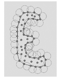
All nodes on an empty sphere with a radius bigger than, are considered as boundary nodes (See Figure 2).
Thus, is a parameter close to, but greater than one. Note that this criterion is coincident with the Alpha Shape concept [47].
|
| Figure 2: Contour recognition: Empty circles with radius define the boundary particles. |
Once a decision has been made concerning which of the nodes are on the boundaries, the boundary surface must be defined. It is well known that in 3-D problems the surface fitting a number of nodes is not unique. For instance, four boundary nodes on the same sphere may define two different boundary surfaces, a concave one and convex one.
In this work, the boundary surface is defined with all the polyhedral surfaces having all their nodes on the boundary and belonging to just one polyhedron.
The correct boundary surface may be important to define the correct normal external to the surface. Furthermore; in weak forms (Galerkin) such as those used here a correct evaluation of the volume domain is also important. Nevertheless, it must be noted that in the criterion proposed above, the error in the boundary surface definition is proportional to . This is the error order accepted in a numerical method for a given node distribution. The only way to obtain more accurate boundary surface definition is by decreasing the distance between the nodes.
7 COMPUTATION OF THE CHARACTERISTIC LENGTHS
The evaluation of the stabilization parameters is one of the crucial issues in stabilized methods. Most of existing methods use expressions which are direct extensions of the values obtained for the simplest 1D case. In this work we will accept the so called SUPG assumption, i.e. to admit that vector has the direction of the velocity field [32-37]. This gives
|
|
(43) |
where and as the “streamline” characteristic length
|
|
(44) |
where are the vectors defining the element sides ( for tetrahedra).
A more consistent evaluation of based on a diminishing residual technique can be found in [37].
8 EXAMPLES
All examples presented here have been obtained withthe fractional step algorithm described in Section 4.2.
8.1 Collapse of a water column
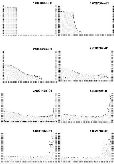
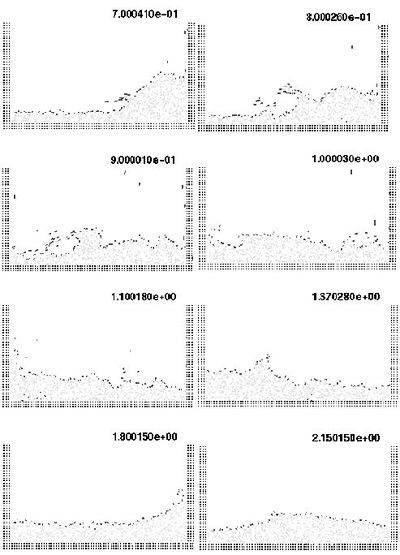
The first problem solved with the lagrangian formulation is the study of the collapse of a water column. This problem was solved by Koshizu and Oka [43] both experimentally and numerically. It has became a classical example to test the validation of the lagrangian formulation in fluid flows. The water is initially located on the left supported by a removable board. The collapse starts at time , when the removable board is removed. Viscosity and surface tension are neglected. Figure 3 shows the point positions at different time steps. The dark points represent the free-surface detected with the algorithms described in Section 5. The internal points are gray and the fixed points are black.
The water is running on the bottom wall until, near sec, it impinges on the right vertical wall. Breaking waves appear at sec. Around sec. the water reaches the left wall. Agreement with the experimental results of [43] both in the shape of the free surface as well as in the time evolution are excellent.
|
|
| Figure 3: Water column collapse at different time steps. |
Figure 3 shows the point positions at different time steps. The darker points represent the free-surface detected.
The water is running on the bottom wall until, near sec, it impinges on the right vertical wall. Breaking waves appear at sec. Around sec. the main water wave reaches the left wall again Agreement with the experimental results of ref. [43] both in the shape of the free surface as well as in the time development are excellent.
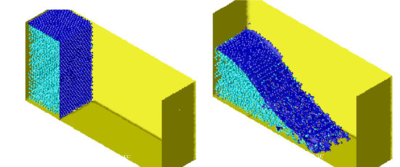
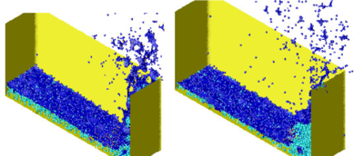
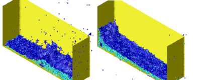
The 3D solution of the same problem is shown in Figure 4.
| |
| |
| |
| Figure 4: Dam collapse in a 3D domain. Different time step. | |
8.2 Semi-submerged rotating water mill
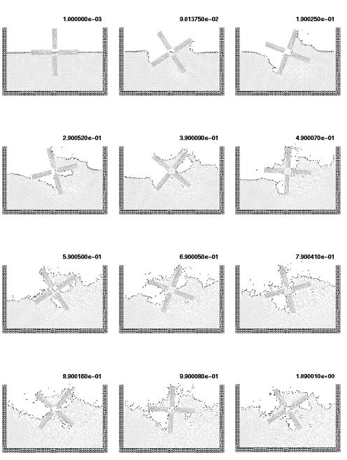
The second example is the analysis of a rotating water mill semi submerged in water. A schematic representation of a water mill is presented in Figure 5. The blades of the mill have an imposed rotating velocity, while the water is initially in a stationary and flat position. Fluid structure interactions with free-surfaces and water fragmentation are well reproduced in this example.
|
| Figure 5: Rotating water mill. |
8.3 Sloshing problems
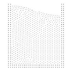
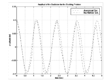
The simple problem of the free oscillation of an incompressible liquid in a container is considered next. Numerical solutions for this problem can be found in several references [44]. This problem is interesting because there is an analytical solution for small amplitudes. Figure 6 shows a schematic of the problem, and represents also the point distribution in the initial position. The dark points represent the fixed points in which the velocity is fixed to zero.
|
| Figure 6: Sloshing. Initial point distribution. |
|
| Figure 7: Sloshing: Comparison of the numerical and analytical solution. |
Figure 7 shows the variation in time of the amplitude compared with the analytical results for the near in viscid case. Little numerical viscosity is observed on the phase wave and amplitude in spite of the relative poor point distribution.
The analytical solution is only acceptable for small wave amplitudes. For larger amplitudes, additional waves are overlapping and finally, the wave breaks and also some particles can be separated from the fluid domain due to their large velocity. Figure 8 shows the numerical results obtained with the method presented in this paper for larger sloshing amplitudes. Breaking waves as well as separation effects can be seen on the free-surface. This particular and very complicated effect is apparently well represented by this model.

|
| Figure 8: Sloshing: Different time step for large amplitudes. |
|
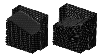
| Figure 9: Sloshing: Different time step for 3D domains. |
In order to test the potentiality of the method in a 3D domain, the same sloshing problem was solved as a 3D problem. Figure 9 show the different point position at two time steps. Each point position was represented by a sphere and only a half of the fixed recipient is represented on the figure. This sphere representation is only used in order to improve the visualization of the numerical results.
8.4 Wave breaking on a beach
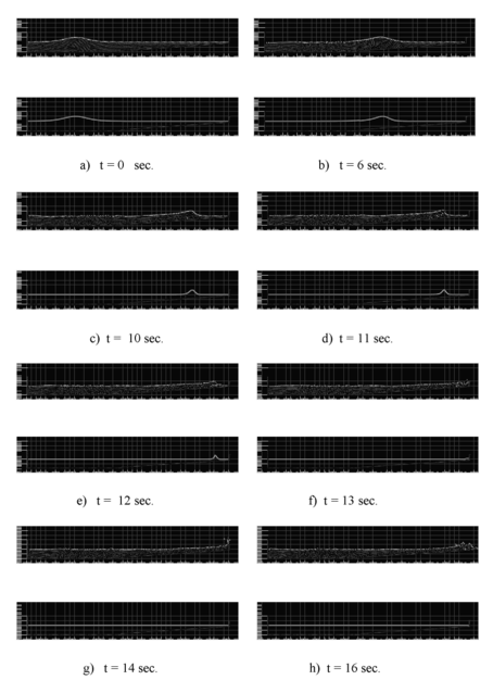
A simulation of the propagation of a water wave and its breaking due to shoaling over a plane slope is presented next. This example was numerically studied in [44] with a lagrangian formulation using directly the standard Finite Element Method with remeshing. There is also an analytical solution for a simplified approximation that is used for comparisons [45]. Figure 10 shows the initial point distribution and Figure 11 a comparison with the analytical free-surface at different time step. The geometry of the problem as well as a discussion of the analytical solution may be found in [44].

|
| Figure 10: Wave breaking on a beach. Initial geometry and point positions. |
Initially (Figures 11.a. and 11.b.) the wave travels over a constant depth bottom towards the slope with no ostensible change of shape. Strongly non-linear effects appear when the wave hits the slope (Fig. 11.c.). The crest of the wave accelerates until it reaches the shore (Fig. 11.d.). At this time the comparisons with the analytical solution are in agreement only in the wave position. The shape of the wave obtained with the numerical solution is totally different. The reason is that the analytical solution gives symmetrical shape waves, which are not physical, before the breaking process. Subsequently, a water jet is formed at the crest plunge making the breaking wave (Figs. 11.e. and 11.f.) and coming in contact with the nearly still surface of the water ahead. In Ref. 44 the evaluation is stopped before this contact point. Using the methodology proposed in this paper, the analysis may be continued until the end. In Figs. 11.g. and 11.h. the wave finally hits a lateral wall (introduced in the model to stop the lateral effects) producing drop separations, and then coming back toward to the left as a new wave.
|
| Figure 11: Wave breaking on a beach. Comparison with analytical results at different time steps. Top: Numerical solution. Bottom: Analytical solution. |
The ability of the model to accurately simulate the various stages of the wave breaking is noteworthy.
Nevertheless, a 2D domain is an easy case, and may be solved acceptably with any mesh generator. The true problems appears in a 3D domain, where the mesh generation is complicated with presence of slivers an other geometric mesh generation problems. In order to show the power of the tool presented, the same problem was solved in a 3D domain.
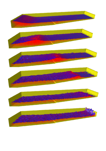
To transform the wave breaking described before in a true 3D problem, the initial position of the wave was introduced having an oblique angle with the beach line. In this way, a 3D effect appears. When the wave hits the slope, the crest of the wave accelerates differently accordingly with the depth, inducing the wave to correct its oblique position and break parallel to the beach. The results may be seen in Figure 12 for different time steps.
|
| Figure 12: Breaking wave on a beach: Oblique wave on a 3D domain. |
8.5 Solid floating on a free-surface
The following example shown schematically in Figure 13 represents a very interesting problem of fluid structure interaction when there is a weak interaction between the fluid and a large rigid deformation of the structure. In this case, there is also a free-surface problem, representing a schematic case of see-keeping in ship hydrodynamics.

|
| Figure 13: Solid floating on a free-surface. Initial geometry and point distribution. |
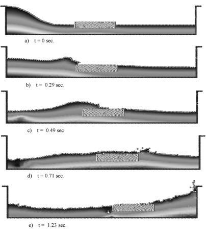
The example shows an initially stationary recipient with a floating piece of wood in which a wave is produced on the left side. The wave intercepts the wood piece producing a breaking wave and moving the floating wood. In this example the solid was represented by very viscous flows with a viscosity parameter order ten times greater than the water viscosity. Figure 14 shows the pressure contours and the free-surface position for different time steps.
|
| Figure 14: Solid floating on a free-surface. Pressure contours and free-surface positions for different time step. |
8.6 Solid cube falling in a recipient with water
This last example is also a case of fluid structure interaction. The solid is initially totally free and is falling down into a recipient with a fluid. In this example, the solid was modeled as a boundary condition for the fluid. Once the pressure and the viscous forces have been evaluated in the fluid, the solid is accelerated using Newton law. The solid has a mass and a gravity force concentrate in its gravity center. The solid is considered to be ligh compared to the liquid weight.
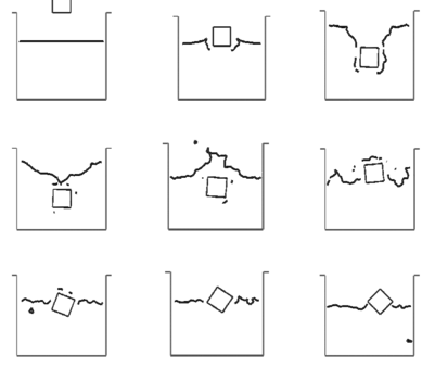
At the beginning the solid falls free due to the gravity forces (Figure 15). Once in contact with the water free-surface, the alpha-shape method recognizes the different boundary contours. The pressure and viscous forces are evaluated in all the domain and in particular on the solid contour. The flow forces introduce a negative acceleration in the vertical direction until , once the solid is completely inside the water, the vertical velocity becomes zero. Then, Arquimides forces bring the solid up to the free-surface. It is interesting to observe that there is a rotation of the solid. The reason is that the center of the floating forces is higher in the rotated position than in the initial ones.
|
| Figure 15: Solid cube falling into a recipient with water. Free- surface position at different time steps. |
9 CONCLUSIONS
The finite calculus expression of the fluid mechanics equations written in a lagrangian frame of reference is a good starting point for deriving stabilized finite element method for solving a variety of fluid flow problems. Both monolithic and fractional step algorithms with intrinsic stabilization properties can be readily derived as shown here. The lagrangian formulation allows to solve in an effective manner fluid flow problems involving large motions of the free surface and complex fluid-structure interactions.
ACKNOWLEDGEMENTS
Thanks are also given to Mr. Romain Aubry for many useful discussions.
References
[1] O.C. Zienkiewicz and R.C. Taylor,The finite element method, 5th Edition, 3 Volumes, Butterworth–Heinemann, 2000.
[2] C. Hirsch, Numerical computation of internal and external flow, J. Wiley, Vol. 1 1988, Vol. 2, 1990.
[3] A.J. Chorin, “A numerical solution for solving incompressible viscous flow problems” J. Comp. Phys., 2, 12–26, 1967.
[4] W.R. Briley, S.S. Neerarambam and D.L. Whitfield, “Multigrid algorithm for three-dimensional incompressible high-Reynolds number turbulent flows”, AIAA Journal, 33 (1), 2073–2079, 1995.
[5] J. Peraire, K. Morgan and J. Peiro, “The simulation of 3D incompressible flows using unstructured grids”, In Frontiers of Computational Fluid Dynamics, Caughey DA and Hafez MM. (eds), Chapter 16, J. Wiley, 1994.
[6] C. Sheng, L.K. Taylor and D.L. Whitfield, “Implicit lower-upper/approximate-factorization schemes for incompressible flows” Journal of Computational Physics, 128 (1), 32–42, 1996.
[7] M. Storti, N. Nigro and S.R. Idelsohn, “Steady state incompressible flows using explicit schemes with an optimal local preconditioning”, Computer Methods in Applied Mechanics and Engineering, 124, 231–252, 1995.
[8] J.C. Heinrich, P.S. Hayakorn and O.C. Zienkiewicz, “An upwind finite element scheme for two dimensional convective transport equations”, Int. J. Num. Meth. Engng., 11, 131–143, 1977.
[9] S.R. Idelsohn, M. Storti and N. Nigro, “Stability analysis of mixed finite element formulation with special mention to stabilized equal-order interpolations” Int. J. for Num. Meth. in Fluids, 20, 1003-1022, 1995.
[10] S.R. Idelsohn, N. Nigro, M. Storti and G. Buscaglia, “A Petrov-Galerkin formulation for advection-reaction-diffusion”, Comput. Meth. Appl. Mech. Engrg., 136, 27–46, 1996.
[11] A. Brooks and T.J.R. Hughes, “Streamline upwind/Petrov-Galerkin formulation for convection dominated flows with particular emphasis on the incompressible Navier-Stokes equations”, Comput. Methods Appl. Mech. Engrg, 32, 199–259, 1982.
[12] T.J.R. Hughes and M. Mallet, “A new finite element formulations for computational fluid dynamics: III. The generalized streamline operator for multidimensional advective-diffusive systems”, Comput Methods Appl. Mech. Engrg., 58, pp. 305–328, 1986.
[13] P. Hansbo and a. Szepessy, “A velocity-pressure streamline diffusion finite element method for the incompressible Navier-Stokes equations”, Comput. Methods Appl. Mech. Engrg., 84, 175–192, 1990.
[14] T.J.R. Hughes, L.P. Franca and M. Balestra, “A new finite element formulation for computational fluid dynamics. V Circumventing the Babuska-Brezzi condition: A stable Petrov-Galerkin formulation of the Stokes problem accomodating equal order interpolations”, Comput. Methods Appl. Mech. Engrg., 59, 85–89, 1986.
[15] L.P. Franca and S.L. Frey, “Stabilized finite element methods: II. The incompressible Navier-Stokes equations”, Comput. Method Appl. Mech. Engrg., Vol. 99, pp. 209–233, 1992.
[16] T.J.R. Hughes, G. Hauke and K. Jansen, “Stabilized finite element methods in fluids: Inspirations, origins, status and recent developments”, in: Recent Developments in Finite Element Analysis. A Book Dedicated to Robert L. Taylor, T.J.R. Hughes, E. Oñate and O.C. Zienkiewicz (Eds.), (International Center for Numerical Methods in Engineering, Barcelona, Spain, pp. 272–292, 1994.
[17] M.A. Cruchaga and E. Oñate, “A finite element formulation for incompressible flow problems using a generalized streamline operator”, Comput. Methods in Appl. Mech. Engrg., 143, 49–67, 1997.
[18] M.A. Cruchaga and E. Oñate, “A generalized streamline finite element approach for the analysis of incompressible flow problems including moving surfaces”, Comput. Methods in Appl. Mech. Engrg., 173, 241–255, 1999.
[19] T.J.R. Hughes, L.P. Franca and G.M. Hulbert, “A new finite element formulation for computational fluid dynamics: VIII. The Galerkin/least-squares method for advective-diffusive equations”, Comput. Methods Appl. Mech. Engrg., 73, pp. 173–189, 1989.
[20] T.E. Tezduyar, S. Mittal, S.E. Ray and R. Shih, “Incompressible flow computations with stabilized bilinear and linear equal order interpolation velocity–pressure elements”, Comput. Methods Appl. Mech. Engrg., 95, 221–242, 1992.
[21] J. Donea, “A Taylor-Galerkin method for convective transport problems”, Int. J. Num. Meth. Engng., 20, 101–119, 1984.
[22] J. Douglas, T.F. Russell, “Numerical methods for convection dominated diffusion problems based on combining the method of characteristics with finite element or finite difference procedures”, SIAM J. Numer. Anal., 19, 871, 1982.
[23] O. Pironneau, “On the transport-diffusion algorithm and its applications to the Navier-Stokes equations”, Numer. Math., 38, 309, 1982.
[24] R. Löhner, K. Morgan, O.C. Zienkiewicz, “The solution of non-linear hyperbolic equation systems by the finite element method”, Int. J. Num. Meth. in Fluids, 4, 1043, 1984.
[25] R. Codina, M. Vazquez and O.C. Zienkiewicz, “A general algorithm for compressible and incompressible flow - Part III. The semi-implicit form” Int. J. Num. Meth. in Fluids, 27, 13–32, 1998.
[26] R. Codina and O.C. Zienkiewicz, “CBS versus GLS stabilization of the incompressible Navier-Stokes equations and the role of the time step as stabilization parameter”, Communications in Numerical Methods in Engineering, 18 (2), 99–112, 2002.
[27] R. Codina and J. Blasco, “Stabilized finite element method for the transient Navier-Stokes equations based on a pressure gradient operator”, Comput. Methods in Appl. Mech. Engrg., 182, 277–301, 2000.
[28] T.J.R. Hughes, “Multiscale phenomena: Green functions, subgrid scale models, bubbles and the origins of stabilized methods”, Comput. Methods Appl. Mech. Engrg, Vol. 127, pp. 387–401, 1995.
[29] F. Brezzi, L.P. Franca, T.J.R. Hughes and A. Russo, ``, Comput. Methods Appl. Mech. Engrg., 145, 329–339, 1997.
[30] R. Codina, “Stabilized finite element approximation of transient incompressible flows using orthogonal subscales”, Comput. Methods Appl. Mech. Engrg., 191, 4295–4321, 2002.
[31] J. Donea and A. Huerta, “Finite element method for flow problems”, J. Wiley, 2003.
[32] E. Oñate, Derivation of stabilized equations for advective-diffusive transport and fluid flow problems, Comput. Meth. Appl. Mech. Engng., Vol. 151, pp. 233–267, (1998).
[33] E. Oñate, J. García and S. Idelsohn, Computation of the stabilization parameter for the finite element solution of advective-diffusive problems, Int. J. Num. Meth. Fluids, Vol. 25, pp. 1385–1407, (1997).
[34] E. Oñate, J. García and S. Idelsohn, An alpha-adaptive approach for stabilized finite element solution of advective-diffusive problems with sharp gradients, New Adv. in Adaptive Comp. Met. in Mech., P. Ladeveze and J.T. Oden (Eds.), Elsevier, (1998).
[35] E. Oñate and M. Manzan, A general procedure for deriving stabilized space-time finite element methods for advective-diffusive problems, Int. J. Num. Meth. Fluids, 31, 203–221, 1999.
[36] E. Oñate and M. Manzan, “Stabilization techniques for finite element analysis of convection diffusion problems”, in Computational Analysis of Heat Transfer, G. Comini and B. Sunden (Eds.), WIT Press, Southampton, 2000.
[37] E. Oñate, “A stabilized finite element method for incompressible viscous flows using a finite increment calculus formulation”, Comp. Meth. Appl. Mech. Engng., 182, 1–2, 355–370, 2000.
[38] E. Oñate and J. García, “A finite element method for fluid-structure interaction with surface waves using a finite calculus formulation”, Comput. MethodsAppl. Mech. Engrg., 191, 635–660, (2001).
[39] E. Oñate, “Possibilities of finite calculus in computational mechanics”, Submitted to Int. J. Num. Meth. Engng., 2002.
[40] E. Oñate and S. Idelsohn, A mesh free finite point method for advective-diffusive transport and fluid flow problems,, Computational Mechanics, 21, 283–292, 1988.
[41] E. Oñate, C. Sacco and S. Idelsohn, “A finite point method for incompressible flow problems”, Computing and Visualization in Science, 2, 67–75, 2000.
[42] J. García and E. Oñate, “An unstructured finite element solver for ship hydrodynamic problems”, in J. Appl. Mech., 70, 18–26, January 2003.
[43] E. Oñate, J. García and S.R. Idelsohn, “Ship hydrodynamics”, in Encyclopedia of Computational Mechanics, E. Stein, R. de Borst and T.J.R. Hughes (Eds), J. Wiley, 2004.
[44] S.R. Idelsohn, E. Oñate, N. Calvo and F. del Pin, “The meshless finite element method”, in Int. J. Num. Meth. Engng., 58, 4, 2003.
[45] S.R. Idelsohn, E. Oñate, F. Del Pin and N. Calvo, “Lagrangian formulation: the only way to solve some free-surface fluid mechanics problems”, Fith World Congress on Computational Mechanics, Mang HA, Rammerstorfer FG and Eberhardsteiner J. (eds), July 7–12, Viena, Austria, 2002, Web...
[46] S.R. Idelsohn, E. Oñate and F. Del Pin, “A lagrangian meshless finite element method applied to fluid-structure interaction problems”, in Computer and Structures, 81, 655–671, 2003.
[47] S.R. Idelsohn, N. Calvo and E. Oñate. Polyhedrization of an arbitrary point set. Comput. Method Appl. Mech. Engng.. Accepted for publication 2003.
[48] H. Edelsbrunner and E.P. Mucke. Three dimensional alpha shapes. ºit ACM Trans. Graphics, 13, 43–72, 1999.
[49] S. Koshizuka and Y. Oka. Moving particle semi-implicit method for fragmentation of incompressible fluid. Nuclear Engineering Science, 123, 421–434, 1996.
[50] R. Radovitzki and M. Ortiz. Lagrangian finite element analysis of Newtonian flows. Int. J. Num. Meth. Engng., 43, 607–619, 1998.
[51] E.V. Laitone. The second approximation to cnoidal waves. Journal of Fluid Mechanics, 9, 430, 1960.
Document information
Published on 01/01/2003
Licence: CC BY-NC-SA license
Share this document
Keywords
claim authorship
Are you one of the authors of this document?