Published in Comput. Meth. Appl. Mech. Engng., Vol. 195 (13-16), pp. 1793–1825, 2006
doi: 10.1016/j.cma.2005.05.036
Abstract
A finite element method (FEM) for steady-state convective-diffusive problems presenting sharp gradients of the solution both in the interior of the domain and in boundary layers is presented. The necessary stabilization of the numerical solution is provided by the Finite Calculus (FIC) approach. The FIC method is based in the solution by the Galerkin FEM of a modified set of governing equations which include characteristic length parameters. It is shown that the FIC balance equation for the multidimensional convection-diffusion problem written in the principal curvature axes of the solution, introduces an orthotropic diffusion which stabilizes the numerical solution both in smooth regions as well in the vicinity of sharp gradients. The dependence of the stabilization terms with the principal curvature directions of the solution makes the method non linear. Details of the iterative scheme to obtain stabilized results are presented together with examples of application which show the efficiency and accuracy of the approach.
1 INTRODUCTION
It is well known that the standard Galerkin FEM solution of the steady-state convective-diffusive equation is unstable for values of the Peclet number greater than one (see Volume 3 in [1]). A number of numerical schemes have been proposed in order to guarantee that the numerical solution is stable, that is, that the solution has a physical meaning. In the first attempts to solve this problem the underdiffusive character of the Galerkin FEM (and the analogous central finite difference scheme) for convective-diffusive problems was corrected by adding “artificial diffusion terms” to the governing equations [1,2]. The relationship of this approach with the upwind finite difference method [2] lead to the derivation of a variety of Petrov-Galerkin FEM. All these methods can be interpreted as extensions of the standard Galerkin variational form of the FEM by adding residual-based integral terms computed over the element domains. Among the many stabilization methods of this or similar kind we name the Upwind FEM [3,4], the Streamline Upwind Petrov-Galerkin (SUPG) method [5-9], the Taylor-Galerkin method [10,11, the generalized Galerkin method [12,13], the Galerkin Least Square method and related approaches [14-16], the Characteristic Galerkin method [17,18], the Characteristic Based Split method [19], the Subgrid Scale method [20-23], the Residual Free Bubbles method [24], the Discontinuous Enrichment Method [25] and the Streamline Upwind with Boundary Terms method [26]. Basically all the methods make use of a single stabilization parameter which suffices to stabilize the numerical solution along the velocity (streamline) direction. The computation of the streamline stabilization parameter for multidimensional problems is usually based on extensions of the optimal value of the parameter for the simpler 1D case. Specific attempts to design the stability parameter for multidimensional problems in the context of the Petrov-Galerkin formulation have been recently reported [27-31]. In general all the stabilized methods above mentioned yield good results for 1D-type problems where the velocity vector is aligned with the direction of the gradient of the solution. However, the use of a single stabilization parameter is insufficient to provide stabilized solutions in the vicinity of sharp gradients not aligned with the velocity direction, which may appear at the interior of the domain or at boundary layers. The usual remedy for these situations is to use the so called “shock capturing” or “discontinuity-capturing” schemes [32-36]. These methods basically add additional transverse diffusion terms in selected elements in order to correct the undershoots and overshoots yielded by the Petrov-Galerkin solution in the sharp gradient zones. Usually the new shock capturing diffusion terms depend on the gradient of the solution and the scheme becomes non linear.
The aim of this work is to develop a general finite element formulation which can provide stabilized numerical results for all range of convective-diffusive problems. The new formulation therefore has the necessary intrinsic features to deal with streamline-type instabilities, as well as with the typical undershoots and overshoots in the vicinity of sharp gradients at different angles with the velocity direction. The new formulation thus provides a unified theoretical and computational framework incorporating all the ingredients of the traditional Petrov-Galerkin and shock-capturing methods.
The formulation proposed is based in the so called Finite Calculus (FIC) approach [37,38]. The FIC method is based in expressing the equation of balance of fluxes in a domain of finite size. This introduces additional stabilizing terms in the differential equations of the infinitessimal theory which are a function of the balance domain dimensions. These dimensions are termed characteristic length parameters and play a key role in the stabilization process.
The modified governing equations lead to stabilized numerical schemes using whatever numerical method. It is interesting that many of the stabilized FEM can be recovered using the FIC formulation. The FIC method has been successfully applied to problems of convection-diffusion [37-41], convection-diffusion-absorption [42,43], incompressible fluid flow [44-47] and incompressible solid mechanics [48,49].
The key to the stabilization in the FIC method is to choose adequately the characteristic length parameters for each element. For 1D problems the standard optimal and critical values of the single stabilization parameter can be found, as shown in Section 3. For 2D/3D problems the characteristic length parameters along each space direction are grouped in a characteristic length vector . Here the key issue is to choose correctly the direction of this vector. It is interesting that if the direction of is taken parallel to that of the velocity, then the resulting FIC stabilized equations coincide with that of the standard SUPG method [37,38].
In previous work of the authors, transverse sharp gradients to the velocity direction were accurately captured by computing iteratively the direction and modulus of vector which minimizes a residual norm [37-41]. In [38] accurate stabilized solutions for convection-diffusion problems with sharp gradients were obtaining by spliting the characteristic lenght vector as the sum of two vectors. The first vector is chosen aligned with the velocity direction, hence yielding the standard SUPG terms, while the second vector is taken parallel to the direction of the gradient of the solution.
In this work a slightly different and more consistent method is proposed. We have found that the key to the general stabilization algorithm for convection-diffusion problems is to express the FIC balance equation taking as coordinate axes the principal curvature directions of the solution. These equations contain the necessary additional diffusion to stabilize the numerical solution in all situations. It is interesting that when one of the principal curvature directions coincides with the velocity direction, then the classical SUPG method is recovered.
The content of the paper is organized as follows. In the next section, the basic FIC equations for the multidimensional steady-state convective-diffusive problem are given. The general equation is particularized for the simple 1D problem and the optimal and critical values of the 1D stabilization parameter are obtained. Then the form of the FIC balance equation written in the principal curvature axes is presented. The computation of the stabilization parameters is detailed and the general iterative solution scheme is explained. The formulation is particularized for linear elements (four node quadrilaterals and three node triangles) where the computation of the curvature directions requires a derivative recovery algorithm. Very good results have been obtained by approximating the main principal curvature direction within the element by the gradient direction at the element center, which is a much more economical approach. A number of examples showing the accuracy and efficiency of the method are presented. Convergence of the iterative scheme in problems with arbitrary sharp gradients was found in most cases in just two iterations.
2 FIC GOVERNING EQUATIONS FOR STEADY-STATE CONVECTION-DIFFUSIVE PROBLEMS
The basic FIC equations are obtained by expressing the balance of fluxes in interior and boundary domains of finite size and retaining one order higher terms in the Taylor expansions than those retained in the infinitessimal theory. The resulting governing equations are
|
|
(1) |
with the boundary conditions
|
|
(2a) |
|
|
(2b) |
where and are the Dirichlet and Neumann boundaries where the variable and the outgoing normal diffusive flux are prescribed to values and , respectively. The modified equation (2b) is obtained by invoking higher order balance of fluxes in a finite domain next to the Neumann boundary [37,38]. In above equations
|
|
(3) |
where is the divergence-free velocity vector, is the diffusion matrix, is the gradient operator, is the external source term and is the normal vector. Vector is the characteristic length vector. For 2D problems , where and are characteristic distances along the sides of the rectangular domain where higher order balance of fluxes is enforced [37,38].
The underlined terms in Equations (1) and (2b) introduce the necessary stabilization in the numerical solution of the convective-diffusive problem [37-41]. The finite element formulation will be presented next.
2.1 Finite element discretization
A finite element interpolation of the unknown can be written as
|
|
(4) |
where are the shape functions and are the nodal values of the approximate function [1].
Application of the Galerkin FE method to Equations (1) and (2b) gives, after integrating by parts the term
|
|
(5) |
The last integral in Equation (5) has been expressed as a sum of the element contributions to allow for interelement discontinuities in the term of Eq.(1), where is the residual of the FE approximation of the infinitesimal governing equation.
Note that the residual terms have disappeared from the Neumann boundary . This is due to the consistency between the FIC terms in Eqs.(1) and (2b).
Integrating by parts the diffusive terms in the first integral of Eq.(5) leads to
|
|
(6) |
In matrix form
|
|
(7) |
Matrix and vector are assembled from the element contributions given by
|
Note that the method is equivalent to modifying the original diffusion matrix by with
|
|
(9) |
In Eq.(9) is the balancing diffusion matrix introduced by the FIC method.
We note that the Galerkin/FIC formulation is residual based, i.e. the stabilization term is a function of the FEM residual which progressively vanishes as the numerical results approaches the “exact” solution (see Eq.(5)). This preserves the consistency of the Galerkin method in order to obtain improved convergence rates with finite elements of any interpolation order. In the following we will restrict the application of the method to linear elements only.
Note that when linear elements are used the second integral of Equation (8a) vanishes. The same happens with the term of the first integral of Equation (8b) when is linear and is constant. Finally, all terms involving the derivatives of vanish if is constant over the element. The evaluation of these integrals is mandatory in any other case.
2.2 Equivalence with the SUPG method
Let us now assume that the direction of vector is parallel to that of the velocity , i.e. where is a characteristic length. Under these conditions, Eq.(5) reads (assuming )
|
|
(10) |
Equation (10) coincides precisely with the SUPG method. The ratio has dimensions of time and it is usually termed element intrinsic time parameter .
The balancing diffusion matrix of Eq.(9) is now given by
|
|
(11) |
It can be shown that the definition of of Eq.(11) is equivalent to introducing an artificial diffusion of value along the streamlines [1,7,9] and this explains the name of the SUPG method. The element characteristic length (or the value of ) is computed in practice by heuristic linear and non-linear extensions of the optimal expression for the 1D problem [5-9,27-31].
In the following sections we will denote by the standard SUPG method to the stabilization procedure leading to a balancing diffusion matrix given by Eq.(11).
It is important to note that the SUPG expression is a particular case of the more general FIC formulation. This explains the limitations of the SUPG method to provide stabilized numerical results in the vicinity of sharp gradients of the solution transverse to the flow direction and the need to introduce in these cases additional shock capturing terms (see Section 5). However, in the FIC formulation the direction of is arbitrary and not necessarily coincident with that of . The components of introduce the necessary stabilization along the streamlines and the transverse directions to the flow. In this manner, the FIC method reproduces the best-features of the so-called stabilized discontinuity-capturing schemes [32-36].
3 COMPUTATION OF THE CHARACTERISTIC LENGTH FOR THE 1D CONVECTION-DIFFUSION EQUATION
The computation of the characteristic length is a crucial step as its value affect to the stability and accuracy of the numerical solution.
Before we face the general multidimensional problem, some based concepts of the computation of the characteristic length for the 1D convection-diffusion equation are briefly given.
The FIC equation for the 1D steady-state convection-diffusion problem is written as
|
|
(12) |
with
|
|
(13) |
where primes denote differentiation with respect to the independent space variable .
The element matrices of Eqs.(8) are now written for two node linear elements as
|
where is the element length and is the coordinate of the end point of the 1D domain where the outgoing flux is prescribed to a value . In Eq.(14a) the space derivatives of have been neglected as is assumed to be constant within each element.
Note that the FIC method introduces a diffusion of value . This term is analogous to that provided by artificial diffusion and upwinding methods [1,2].
The characteristic length parameter for each element can be made proportional to the element length as where is an element stabilization parameter. A typical stencil for a mesh of uniform size 1D elements of length is written as
|
|
(15) |
Injecting into Eq.(15) the exact analytical solution where and are contants, gives the optimal value of yielding the exact solution at the nodes with
|
|
(16) |
where is the element Peclet number.
A critical value of ensuring physically correct results can be found by writing the stencil (15) for a two element mesh with nodes 1, 2 and 3 and Dirichlet boundary conditions and . The resulting equation reads
|
|
(17) |
An unphysical (unstable) solution will imply . This is avoided if the following value of is chosen with
|
|
(18) |
where is termed the critical stabilization parameter. It can be verified that that for . Note that both and are constant within each element, as initially assumed.
Above well know results from the finite element and finite difference literature will be useful for the general multidimensional case described next.
Remark 1. The stabilizing diffusion of Eq.(15) can be expressed in terms of the equivalent intrinsic time parameter by replacing the term by where . The optimal and critical values of are therefore obtained by dividing by the expressions of and of Eqs.(16) and (18), respectively.
4 COMPUTATION OF THE CHARACTERISTIC LENGTH VECTOR
We present here a general procedure to compute the characteristic length vector for convection-diffusion problems. For the sake of preciseness the method is explained for 2D problems although it is equally applicable to 3D problems.
|
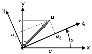
| Figure 1: Global axes () and principal curvature axes () |
Let us write down the FIC balance equation in the principal curvature axes of the solution (Figure 1). For simplicity we consider the 2D sourceless case () with an isotropic diffusion defined by a constant diffusion parameter . The FIC balance equation is
|
|
(19) |
where are the velocities along the principal axes of curvature and , respectively.
As and are the principal curvature axes of the solution then
|
|
(20) |
Introducing this simplification into Eq.(19) we can rewrite this equation as
|
|
(21) |
We can see clearly from Eq.(21) that the FIC governing equations introduce orthotopic diffusion parameters of values and along the and axes, respectively. Also note that the last term of Eq.(21) will vanish after discretization for linear elements.
Eq.(21) can be rewritten in matrix form (neglecting the last term) as
|
|
(22) |
where , , is the “physical” isotropic diffusion matrix and is the balancing diffusion matrix in the local axes and . The form of these matrices is
|
|
(23) |
The velocities along the principal curvature axes and can be obtained by projecting the cartesian velocities into the principal curvature axes and as
|
|
(24) |
where , and is the angle which the axis forms with the axis (Figure 1). Note that as the solution is continuous the principal curvature directions and are orthogonal.
The characteristic length distances and are defined as
|
|
(25) |
where and are typical element dimensions along the and axes, respectively and and are the corresponding stabilization parameters.
The values of and are computed by considering the solution of two uncoupled 1D problems along the and directions. This gives from Eq.(16)
|
The lengths and are taken as the maximum projection of the velocities and along the element sides (for triangles) and the element diagonals (for quadrilaterals), i.e.
|
|
(27.a) |
with
|
|
(27.b) |
In Eq.(27a) and contain the global components of the velocity vectors and , respectively. For triangles are the element sides vectors, whereas for quadrilaterals are the element diagonals vectors.
The next step is to transform Eq.(22) to global axes . The resulting equation is written as
|
|
(28) |
where the global diffusion matrix is
|
|
(29a) |
The isotropic diffusion matrix is given by Eq.(23) and the global balancing diffusion matrix is
|
|
(29b) |
where the transformation matrix T is given in Eq.(24).
Remark 2. We can write the local balancing diffusion matrix of Eq.(23) for as
|
|
(30a) |
where
|
|
(30b) |
If is greater than a similar split is performed with in the position 22 of matrix and is replaced by in .
Eq.(30a) shows that the diffusivity matrix is equivalent to the sum of a balancing diffusion along the principal curvature direction (or if ) and an isotropic diffusion matrix
The global balancing diffusion matrix of Eq.(29a) can therefore be written as
|
|
(31) |
Clearly, if the principal curvature direction is parallel to the velocity direction, then , , and
|
|
(32) |
where and is computed by Eq.(26a). Note that the method coincides with the standard SUPG approach in this case.
Remark 3. The global balance diffusion matrix can be also computed from the expression of vector in global axes as
|
|
(33) |
where and is the transformation matrix of Eq.(24). The proof of this equivalence is given in the Appendix. In our computation however we have chosen to compute the balancing diffusion matrix via Eqs.(23)–(29).
4.1 Computation of the principal curvature axes for linear elements
The principal curvature axes can be estimated as the eigenvectors of the curvature matrix
|
|
(34) |
In general matrix C varies within each element.
Computation of the second derivatives field for linear elements is not straightforward and it requires the nodal recovery of the first derivative field. This can be performed by using a simple nodal averaging procedure or more sophisticated superconvergence patch recovery techniques for the first derivative field [50,51].
Excellent results have been obtained by the authors in this work by approximating the principal curvature direction by the direction of the gradient vector .
This simplification allows us to estimate the direction in a very economical manner as the gradient vector can be directly computed at any point of a linear element. Direction is taken orthogonal to that of in an anti-clockwise sense.
For linear triangles is constant within the element. For four node quadrilaterals varies linearly. We have assumed in this case that the direction of is constant within the element and equal to that of vector computed at the element center.
The dependence of the balancing diffusion matrix with the principal curvature directions and introduces a non linearity in the solution process. A simple and effective iterative algorithm is described next.
4.2 General iterative scheme
A stabilized numerical solution can be found by the following algorithm.
Step 0 (SUPG step). At each integration point choose , i.e. the gradient direction is taken coincident with the velocity direction. Compute , and from Eqs.(23–29). The expression of the balancing diffusion matrix coincides now precisely with the standard (linear) SUPG form.
Solve for .
Verify that the solution is stable. This can be performed by verifying that there are not undershoots or overshoots in the numerical results with respect to the expected physical values. If the SUPG solution is unstable, then implement the following iterative scheme.
For each iteration:
Step 1 Compute at the element center. . Then compute , and .
Solve for .
Step 2 Estimate the convergence of the process. We have chosen the following convergence norm
|
|
(35) |
where is the total number of nodes in the mesh and is the maximum prescribed value at the Dirichlet boundary (if then ). In above steps the left upper indices denote the iteration number.
In the examples shown in the next section has been taken in Eq.(35).
If condition (35) is not satisfied, start a new iteration and repeat steps 1 and 2 until convergence. Indexes 0 and 1 are replaced now by and , respectively.
Remark 4. The convergence of the iterative scheme of the previous section obviously depends on the “quality” of the standard SUPG solution obtained in Step 0. Clearly when boundary layers or sharp transverse internal layers dominate the solution, the non linearity of the processes increases. The authors have found that the convergence of the scheme can be substantially improved in some problems if the following expression for the stabilizing dissipation matrix is used in Step 1
|
|
(36) |
where is a relaxation factor such that .
Convergence of the iterative scheme was achieved in just two iteration in Examples 6.1–6.3 for values of between 0.8 and 1. The best solution in Example 6.4 was found in five iterations for . This is due to the higher non linearity of the process induced by the transverse boundary layers in this case.
Remark 5. The direct iterative scheme presented in Section 4.2 is obviously not the only option to solve the non linear equations resulting from the dependence of the stabilizing diffusion matrix with the principal curvatures of the solution.
A simple and economical alternative is to use a time relaxation technique based in the solution of a pseudo transient problem with a forward Euler scheme and a diagonal mass matrix. This technique was used by Codina in [9,33] for solving a similar class of convection-diffusion problems.
5 EQUIVALENCE WITH SUPG AND SHOCK-CAPTURING TECHNIQUES
As mentioned earlier, the SUPG formulation based on the use of a stabilization term of the form shown in Eq.(10) has severe limitations to provide stabilized solutions (i.e. without overshoots and undershoots) in the vicinity of sharp gradients of the solution transverse to the flow direction. The usual remedy in these cases is to introduce an additional stabilization term (the shock capturing term).
In esence all shock capturing formulations are equivalent to an split of the stabilization term in two parts. One part is taken equal to the standard linear SUPG term. This term suffices to stabilize the effect of the gradient of the solution in the direction of the velocity. The second part is introduced in order to account for gradients of the solution along a direction not aligned with the velocity. This second term (the shock capturing or transverse diffusion term) usually involves the velocity projection along the gradient direction. This term introduces therefore a non linearity in the solution process. The usual approach is to start by computing the linear SUPG solution, check if there are sharp transverse gradients which deserve further stabilization and, if so, introduce the shock capturing term and iterate until a stabilized solution is found in the whole domain.
Despite their effectiveness, most shock capturing methods lack of a general theoretical framework and can be viewed as “ad hoc” extensions of the SUPG method. A serious drawback of these methods is that, in some cases, the amount of transverse diffusion can not be properly controlled and hence the final solution is either underdiffusive or overdiffusive.
The general stabilized formulation we propose here includes the best features of the SUPG and shock capturing techniques. The iterative scheme in fact follows the lines of the standard shock capturing methods [32-36]. The innovation in the proposed formulation lays in the definition of the shock capturing terms, which are deduced form the FIC governing equations written in the principal curvature directions. Numerical results obtained in all examples show that the method preserves the quality of the numerical solution in all situations by introducing the necessary streamline and transverse dissipation.
A similar shock capturing method of this kind was proposed by Oñate [38] in the context of the FIC approach. There the characteristic length vector was split as the sum of a vector along the velocity direction (the linear SUPG term) and a vector in the direction of the solution gradient (the non linear schock capturing term). Good results were obtained with this method for a variety of advection-diffusion problems [38]. The formulation we present here is more general as it encompasses the SUPG method and the shock capturing strategy in a unified approach.
We have shown in Remark 2 that the proposed approach coincides with the standard SUPG method (with no discontinuity capturing) when the principal direction is parallel to the velocity direction. This analogy is discussed further next.
Let us split the characteristic vector as the sum of two vectors along the velocity and the gradient directions respectively as
|
|
(37) |
where and are the characteristic lengths along the velocity and gradient directions, respectively. When is linear (i.e., independent of the solution) the first term in the r.h.s of Eq.(37) is the classical SUPG term. The second term depending on the solution gradient is the shock-capturing term.
Eq.(37) allows to solve for and in terms of the components of and as
|
|
(38.a) |
|
|
(38.b) |
where and are computed from and by Eq.(33).
Eqs.(38) clearly show that in the general case the expressions of and are a function of the numerical solution . Hence, for arbitrary orientations of the principal curvature direction , the stabilized method proposed can be interpreted as the combination of a non linear SUPG term and a non linear shock capturing term. The introduction of this gradient-dependent non linearity in the SUPG term is one of the distinct features of the new formulation.
When the principal curvature direction is parallel to the velocity direction then and
|
|
(39a) |
Hence
|
|
(39b) |
and the method coincides in this case with the standard linear SUPG approach, as expected.
A case of practical interest is when the directions of and are orthogonal. This occurs for some specific distributions of the velocity and the solution fields or in the vicinity of sharp layers when the mesh is fine enough, or it has some specific orientation. In these cases we have
|
|
(40) |
Hence from Eq.(33)
|
|
(41.a) |
and from Eqs.(38)
|
|
(41.b) |
Once again, the linear SUPG method is recovered and the stabilized formulation does not introduce any additional transverse dissipation, as should be expected.
Remark 6. From above arguments we conclude that the simplified expression with being a non linear function of the solution leads to a non linear SUPG term. This has a similarity with the non linear SUPG formulation reported in [28,31]. We have found that in general this assumption does not suffice to stabilize the solution in presence of high gradients transverse to the solution. In these cases the introduction of the term involving in Eq.(37) is essential in order to obtain an improved solution.
6 EXAMPLES
The efficiency of the algorithm is verified in a number of examples of application including sharp gradients at the interior of the domain as well as in boundary layers. The examples show the ability of the algorithm to provide a stabilized and accurate solution in all cases in very few iterations. All units in the examples are in the International System.
In the examples solved a solution is consider unstable if where and are the maximum and minimum prescribed values of at the Dirichlet boundaries. The parameter has been taken equal to . This condition basically ensures that the solution has no overshoots or undershoots with respect to the prescribed boundary values.
In all examples presented the classical SUPG results (with no discontinuity capturing) are compared with those obtained with the FIC iterative scheme. Examples 6.1–6.3 were solved for a value of in Eq.(36). A converged and accurate solution was obtained in all cases in just two iterations. The convergence process was quite insensitive to the value of for values of ranging between 0.8 and 1.0. We note that good stabilized results were also obtained in these examples using just one iteration. However, a slight increase in the accuracy of the results was obtained using two iterations, while no significant increase in accuracy was reached by iterating any further.
The FIC solution reported for Example 6.4 was obtained in five iterations for a value of in Eq.(36).
We finally note that most of the examples presented have been successfully solved in the past using different shock capturing techniques [32-36]. In this paper the FIC results are compared with values obtained using the standard (linear) SUPG formulation. The basic aim of the examples presented here is to show that the FIC formulation integrates naturally the best features of both the SUPG and the shock capturing formulations.
6.1 Square domain with uniform Dirichlet conditions, upward diagonal velocity and zero source
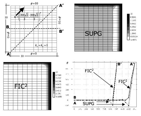
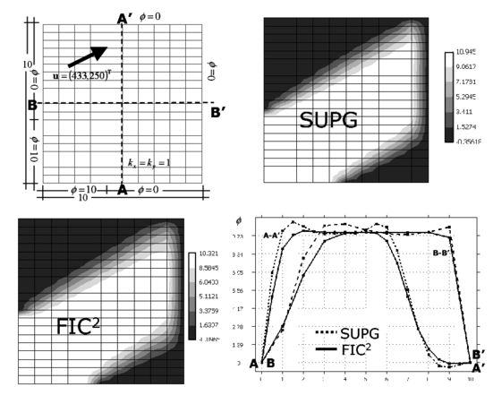
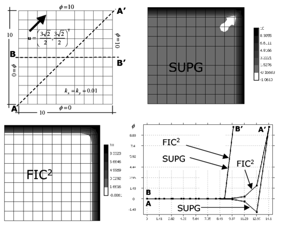
Figure 2 shows the geometry of the analysis domain and the boundary conditions. The domain is a square of side equal to 10. Zero values of the variable are prescribed at the inlet boundaries and , whereas is prescribed at the outlet boundaries and . The isotropic diffusion and the velocity vectors are taken parallel to the diagonal of the domain with . The problem has been solved with the structured mesh of four node rectangles shown in the figure. The Peclet number along the velocity direction is .
|
| Figure 2: Square domain with uniform Dirichlet conditions, upward diagonal velocity and zero source. SUPG and FIC solutions obtained with a structured mesh of linear four node square elements |
Results in Figure 2 show contours of the numerical solution for the SUPG and the FIC iterative scheme proposed. FIC in the figures denotes results obtained after two iterations of the scheme described in Section 4.2. A value of in Eq.(36) has been chosen. Note that the SUPG method yields incorrect negative values of in the vicinity of the upper right corner, as expected, whereas the FIC results are physically correct over the domain. A plot of the distribution of the solution along the horizontal center line and the diagonal line is shown. The difference between the FIC and SUPG results along the diagonal line is clearly seen.
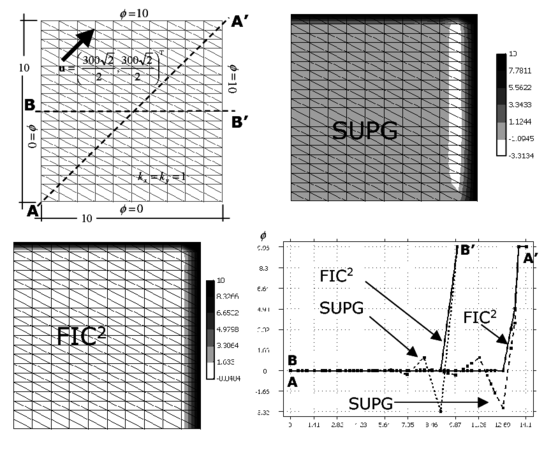
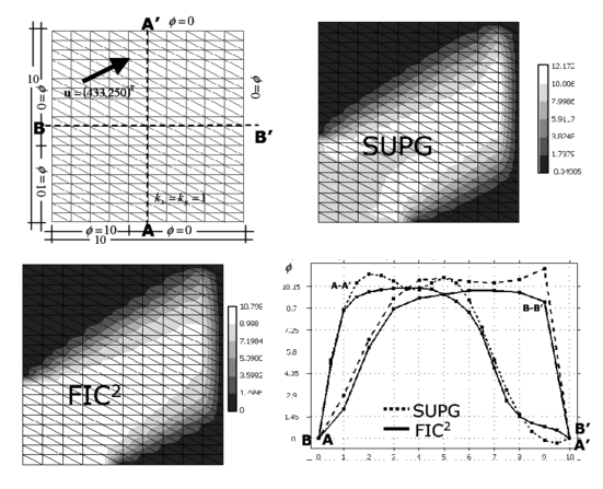
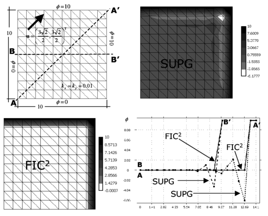
Figure 3 shows results for the same problem solved with a structurerd mesh of three node triangular elements. The effect of the stabilization process in more visible in this case as the SUPG solution has more undershoots than for four node square elements.
|
| Figure 3: Square domain with uniform Dirichlet conditions, upward diagonal velocity and zero source. SUPG and FIC solutions obtained with a structured mesh of linear three node triangles |
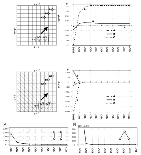
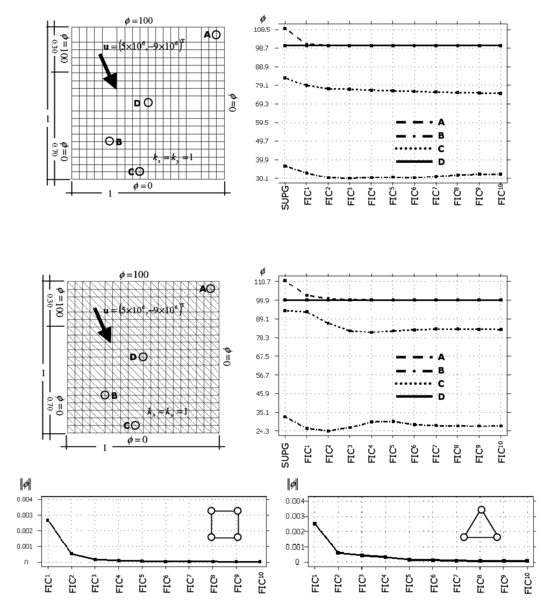
The convergence of the iterative process using square and triangular elements is plotted in Figure 4 where the evolution of the values of at three different points within the analysis domain is plotted. The evolution of the norm of Eq.(35) with the number of iterations is also shown. Note that a converged solution () is obtained in just two iterations.
|
| Figure 4: Square domain with uniform Dirichlet conditions, upward diagonal velocity and zero source. Convergence of the FIC solution for square and triangular elements |
Figures 5 and 6 show the solution of a similar problem using the same number of four node rectangular elements and linear triangles with a geometrical aspect ratio of 2:1. The SUPG solution of both cases is clearly non physical and the FIC iterative process provides again a stabilized and accurate solution in just two iterations.
6.2 Square domain with non uniform Dirichlet conditions, downwards diagonal velocity and zero source
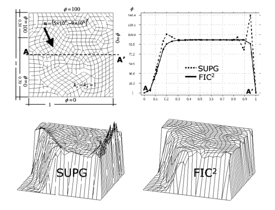
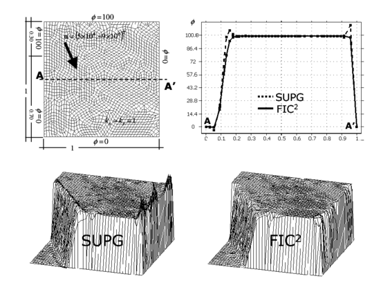
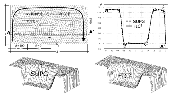
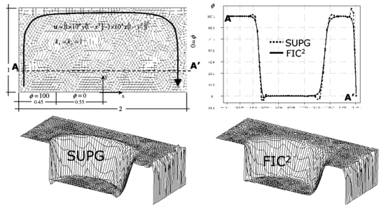
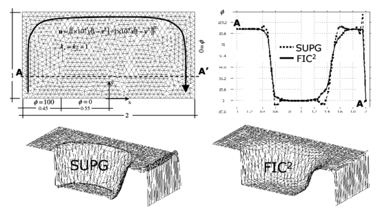
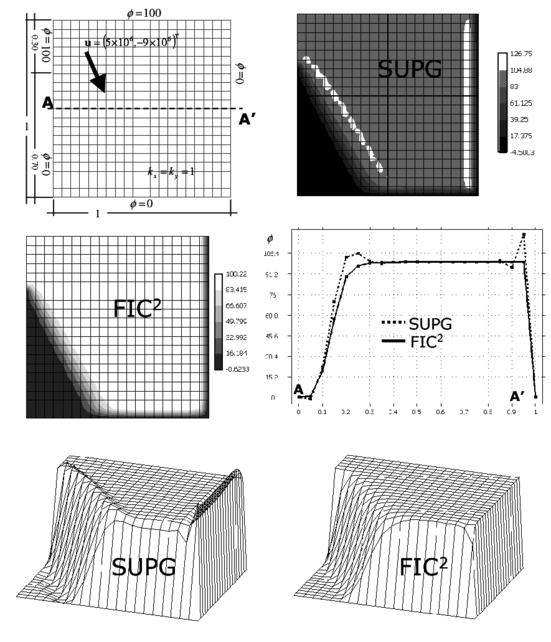
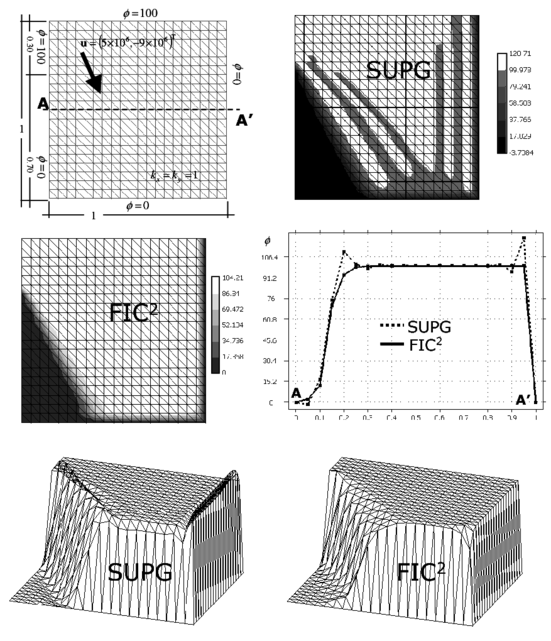
The geometry of the problem and the boundary conditions are shown in Figure 7. The side of the square domain has a length equal to one. The velocity vector is . An isotropic diffusion of unit value is assumed. The correct solution is a uniform plateau of value with an internal sharp layer in the vicinity of the left lower region where the solution drops to , a boundary layer at the right hand side and at partial boundary layer at the bottom side where the value of is prescribed to zero.
|
| Figure 7: Square domain with non uniform Dirichlet conditions, downwards diagonal velocity and zero source. SUPG and FIC solutions obtained with a structured mesh of linear four node square elements |
Figures 7 and 8 show results obtained with structured meshes of four node square elements and linear triangles, respectively. The SUPG solution in both cases has overshoots in the vicinity of the sharp gradient zones, whereas the FIC iterative scheme yields a stabilized and accurate solution in two iterations. Again in Eq.(36) was chosen. Note that the boundary layers and the internal sharp gradient zone are well captured without overshoots or undershoots with the FIC method using both types of elements.
|
| Figure 8: Square domain with non uniform Dirichlet conditions, downwards diagonal velocity and zero source. SUPG and FIC solutions obtained with a structured mesh of three node triangles |
The convergence of the process for both elements is shown in Figure 9.
|
| Figure 9: Square domain with uniform Dirichlet conditions, upward diagonal velocity and zero source. Convergence of the FIC solution for square and triangular elements |
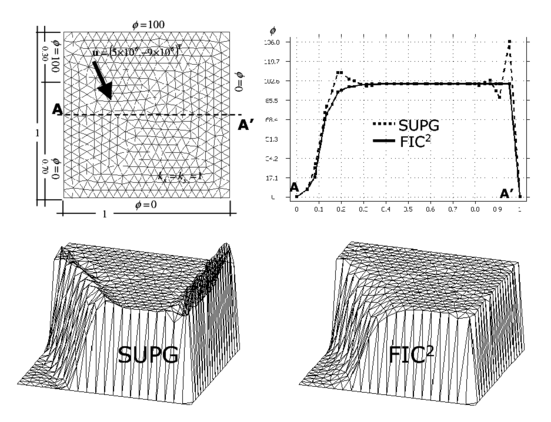
Figures 10 and 11 show results for the same problem using coarse and refined unstructured meshes of linear quadrilaterals and triangles, respectively. The performance of the FIC algorithm is very good in both cases despite the difficulty to capture the sharp layers with coarse unstructured meshes.
|
| Figure 11: Square domain with non uniform Dirichlet conditions, downwards diagonal velocity and zero source. SUPG and FIC solutions obtained with an unstructured mesh of 780 three node triangles |
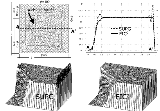
The solution is improved in both cases by using a refined unstructured mesh as shown in Figures 12 and 13. Note that the overall solutions obtained with the linear triangle and unstructured meshes are slightly better than those obtained with linear quadrilaterals for a similar number of elements. The improvements are clearer in the vicinity of the boundary layer at the right hand side of the domain.
|
| Figure 13: Square domain with non uniform Dirichlet conditions, downwards diagonal velocity and zero source. SUPG and FIC solutions obtained with a refined unstructured mesh of 1898 linear triangles |
Figures 14 and 15 show results for a similar problem solved now with structured meshes of linear rectangles and triangles with a geometrical aspect ratio of 2:1. The correct solution in this case is a central plateau of with a boundary layer at the right hand side where the solution drops to , and two sharp gradient zones at both sides of the plateau within the domain. The figures show the contours of over the analysis domain and the distribution of along the vertical and horizontal central lines. As expected the SUPG solution yields over and undershoots. Two iterations of the FIC iterative scheme again suffice to provide a correct solution over the whole domain.
This problem has been chosen by many authors as a test for stabilized formulations. A comparison of the solution obtained with different shock capturing techniques was reported by Codina [9,33] using a time relaxation scheme. The FIC results presented here reproduce the best results obtained for this problem with the shock capturing methods analyzed in [9,33].
6.3 Rectangular domain with Neumann and non uniform Dirichlet conditions, rotational velocity field and zero source
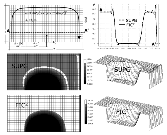
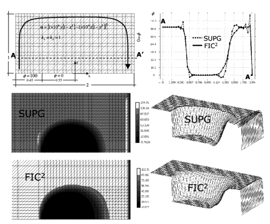
The rectangular domain of sides units and the boundary conditions are shown in Figure 16. The rotational velocity field is defined by . A unit isotropic diffusion is assumed. The velocity is prescribed at the domain sides shown. In the rest of the sides the Neumann boundary condition with is assumed. The correct solution is a uniform plateau of with a boundary layer at the right hand side where the solution drops towards the prescribed value of and a circular sharp gradient region around the lower circular zone where the solution takes a zero value.
Figures 16 and 17 present the results obtained with the structured meshes of linear square and triangular elements respectively shown. The contours of over the domain and the distribution of the solution along an horizontal line are plotted. Results clearly show the incapacity of the SUPG method to correctly capture the boundary layer and the internal gradient region. The solution obtained with two iterations of the FIC scheme presented is physically sound and accurate over the whole analysis domain as shown in the figures. FIC results were once more obtained for a value of in Eq.(36).
Figure 18 shows results for the solution of the same problem using coarse and refined unstructured meshes of linear quadrilaterals. Note the accuracy of the FIC stabilized solution, even for the coarse mesh.
The same problem was finally solved with a unstructured mesh of 1554 linear triangles. The number of elements chosen is quite similar to that used for the structured solution (1600 elements). The solution obtained shown in Figure 19 is quite accurate over the whole domain, despite the relative coarseness of the mesh. This is another prove of the best performance of the linear triangle in unstructured meshes.
6.4 Square domain with homogeneous Dirichlet condition and constant source
The computational domain for this last example is again the unit square, discretized now with uniform meshes of 20 20 linear quadrilateral and three node triangles. The value of is prescribed to zero on the whole boundary. The velocity vector is and the isotropic diffusion is . A uniformly distributed source over the whole domain has been taken.
The correct solution of this problem is a linear distribution of increasing uniformly from a value of zero at the inlet boundary until it reaches a maximum value in the vecinity of the outlet boundary. Three boundary layers exist for this problem, one at the exit boundary and two at the two lateral sides, where the value of drops drastically to zero. Figures 20 and 21 show results obtained with the two structured meshes of quadrilateral and triangles, respectively. The linear SUPG solution yields oscillations in the direction normal to the lateral layers, although a good resolution of the layer normal to the velocity field is obtained, as expected. The FIC solution for in Eq.(36) yielded a smoooth solution near the boundary layers, free of the lateral oscillations which are present in the SUPG solution. The best FIC solution in this case was however obtained for a value of in Eq.(36). Five iterations of the scheme were needed to obtain convergence in this case. The numerical results obtained for both meshes are shown in Figures 20 and 21.
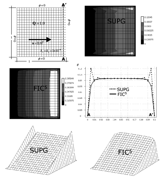
|
| Figure 20: Square domain with homogeneous Dirichlet conditions and constant source. Solution for a structural mesh of four node quadrilaterals |
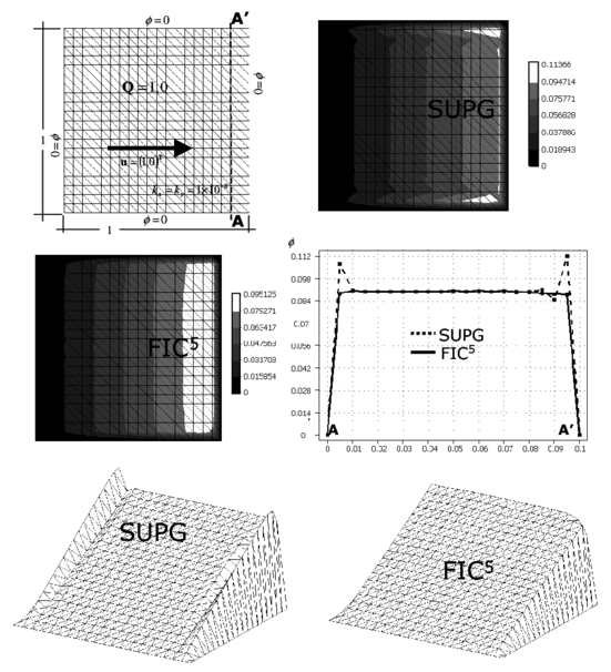
|
| Figure 21: Square domain with homogeneous Dirichlet conditions and constant source. Solution for an unstructured mesh of three node triangles |
This problem was also studied by Codina [9,33] with four node square elements as another benchmark to study the performance of different shock capturing methods. The FIC method proposed here has yielded accurate solutions for both quadrilateral and triangular elements, which are difficult to obtain for many of the existing stabilization procedures, as reported in [9,33].
7 CONCLUDING REMARKS
The FIC governing equations for the convection-diffusion problem written in the principal curvature directions introduce naturally the necessary balancing diffusion terms to accurately solve convection dominated problems with sharp internal gradients and boundary layers. In our computations over four node quadrilaterals and three node triangles very good results have been obtained by assuming that the principal curvature direction is constant over each element and equal to the direction of the gradient vector at the element center.
The dependence of the balancing diffusion with the solution gradient makes the stabilization process non linear. An efficient iterative scheme has been proposed where the standard SUPG formulation is used to obtain an initial solution. Convergence of the iterative scheme has proved to be very fast in all problems solved.
The balancing diffusion terms can be interpreted as the sum of a non linear SUPG diffusion term and a non linear shock capturing term. If the velocity is parallel to the gradient vector, then the standard (linear) SUPG term is recovered.
The efficiency and accuracy of the method was tested in a number of problems with arbitrary sharp gradients solved with structured and unstructured meshes of linear quadrilaterals and triangles.
Very accurate results were obtained in just two iterations for most of the problems solved (Examples 6.1–6.3). One iteration sufficed to provide good quality stabilized results in many cases.
As a general rule, both linear triangles and bilinear quadrilaterals yielded similar good results for structured meshes. The linear triangle shows a slightly superior performance for unstructured meshes.
The examples presented show that the FIC formulation incorporates in a unified theoretical and computational framework the best features of the classical streamline stabilization methods and shock capturing techniques.
ACKNOWLEDGEMENTS
The authors thank S. Badia, C. Felippa, R. Löhner, R.L. Taylor and O.C. Zienkiewicz for many useful discussions.
APPENDIX A
Computation of the balancing diffusion matrix in local and global axesComputation of the balancing diffusion matrix
D
¯
{\displaystyle {\overline {\textbf {D}}}}
in local and global axes
The balancing diffusion matrix can be computed by transforming the local matrix of Eq.(23) to global axes, or by using directly Eq.(33). We will prove next that both expressions yield the same system of governing differential equations, i.e. we will prove that
|
|
(A.1) |
where
|
|
(A.2) |
and
|
In above where is the angle that the principal curvature axis forms with the global direction . The characteristic length distances and are computed as described in Eqs.(25–27).
In order to prove the identity in Eq.(A.1) we proceed as follows
|
|
(A.5) |
|
|
(A.6) |
On the other hand
|
|
(A.7) |
Finally
|
|
(A.8) |
Clearly Eqs.(A.6) and (A.8) coincide if the last term in Eq.(A.8) is zero. This happens when and are the principal curvature directions. In order to prove this we will consider the usual case for which and both principal curvature directions are orthogonal. Then it exists a transformation matrix such that
|
|
(A.9) |
with defined as in Eq.(A.2).
The condition which ensures a diagonal matrix in the r.h.s. of Eq.(A.9) is
|
|
(A.10) |
which is precisely the condition which cancels out the last term in Eq.(A.8).
Hence the identity of Eq.(A.1) is satisfied.
REFERENCES
[1] Zienkiewicz O.C. and Taylor R.L. The finite element method. 5th Edition, 3 Volumes, Butterworth–Heinemann, 2000.
[2] Hirsch C. Numerical computation of internal and external flow, J. Wiley, Vol. 1 1988, Vol. 2, 1990.
[3] Heinrich J.C., Huyakorn P.S. and Zienkiewicz O.C. An upwind finite element scheme for two dimensional convective transport equations, Int. J. Num. Meth. Engng., 11, 131–143, 1977.
[4] Kelly D.W., Nakazawa S., Zienkiewicz O.C. and Heinrich J.C. A note on upwind and anisotropic balancing dissipation in finite element approximation to convective diffusion problems. Int. J. Num. Meth. Engng., 15, pp. 1705–1711, 1980.
[5] Brooks A.N. and Hughes T.J.R. Streamline upwind/Petrov-Galerkin formulation for convection dominated flows with particular emphasis on the incompressible Navier-Stokes equations. Comput. Methods Appl. Mech. Engrg., 32, 199–259, 1982.
[6] Hughes T.J.R and Tezduyar, T.E. Finite element method for first order hyperbolic systems with particular emphasis on the compressible Euler equations. Comput. Meth. Appl. Mech. Engng., 45, 217–284, 1984.
[7] Hughes T.J.R and Mallet M. A new finite element formulations for computational fluid dynamics: III. The generalized streamline operator for multidimensional advective-diffusive systems. Comput Methods Appl. Mech. Engrg., 58, 305–328, 1986a.
[8] Codina R., Oñate E. and Cervera M. The intrinsic time for the streamline-upwind Petrov-Galerkin formulation using quadratic elements. Int. J. Num. Meth. Engrg., 94, 239–262, 1992.
[9] Codina R. A finite element formulation for the numerical solution of the convection-diffusion equations. Monograph no. 14, CIMNE, Barcelona 1993.
[10] Donea J. A Taylor-Galerkin method for convective transport problems. Int. J. Num. Meth. Engng., 20, pp. 101–119, 1984.
[11] Donea J. and Huerta A. Finite element methods for flow problems. J. Wiley, 2003.
[12] Donea J., Belytschko T. and Smolinski P. A generalized Galerkin method for steady state convection-diffusion problems with applications to quadratic shape functions elements. Comp. Meth. Appl. Mech. Engng., 48, 25–43, 1985.
[13] Goldschmit M.B. and Dvorkin E.N. On the solution of the steady-state convection-diffusion equation using quadratic elements. A generalized Galerkin technique also reliable with distorted meshes. Engng. Comput., 11, 6, 565–579, 1994.
[14] Hughes T.J.R, Franca L.P. and Hulbert G.M. A new finite element formulation for computational fluid dynamics: VIII. The Galerkin/least-squares method for advective-diffusive equations. Comput. Methods Appl. Mech. Engrg., 73, 173–189, 1989.
[15] Franca L.P., Frey S.L. and Hughes T.J.R. Stabilized finite element methods: I. Application to the advective-diffusive model. Comput. Meth. Appl. Mech. Engn, Vol. 95, pp. 253–276, 1992.
[16] Franca L.P. and Dutra do Carmo E.G. The Galerkin Gradient Least Square method. Comput. Methods Appl. Mech. Engrg., 74, 41–54, 1989.
[17] Douglas J. and Russell T.F. Numerical methods for convection dominated diffusion problems based on combining the method of characteristics with finite element or finite difference procedures. SIAM J. Numer. Anal., 19, 871, 1982.
[18] Löhner R., Morgan K. and Zienkiewicz O.C. The solution of non-linear hyperbolic equation systems by the finite element method. Int. J. Num. Meth. in Fluids, 4, 1043, 1984.
[19] Zienkiewicz O.C. and Codina R. A general algorithm for compressible and incompressible flow. Part I: The split characteristic based scheme. Int. J. Num. Meth. in Fluids, 20, 869-85, 1995.
[20] Hughes T.J.R. Multiscale phenomena: Green functions, subgrid scale models, bubbles and the origins of stabilized methods. Comput. Methods Appl. Mech. Engrg 1995, 127, 387–401, 1995.
[21] Brezzi F., Franca L.P., Hughes T.J.R. and Russo A. . Comput. Methods Appl. Mech. Engrg., 145, 329–339, 1997.
[22] Codina R. Stabilization of incompressibility and convection through orthogonal sub-scales in finite element method. Comput. Methods Appl. Mech. Engrg., 190, 1579–1599, 2000.
[23] Hauke G. A simple subgrid scale stabilized method for the advection-diffusion-reaction equation. Comput. Methods Appl. Mech. Engrg., 191, 2925–2948, 2002.
[24] Brezzi, F. and Russo A. Choosing bubbles for advection-diffusion problems. Math Models Methods Appl. Sci., 4, 571–587, 1994.
[25] Farhat C., Harari I. and Franca L.P. The discontinuous enrichment method. Comput. Methods Appl. Mech. Engrg., 190, 6455–6479, 2001.
[26] Ilinca F., Hétu J.F. and Pelletier D. On stabilized finite element formulation for incompressible advective-diffusive transport and fluid flow problems. Comput. Methods Appl. Mech. Engrg., 188, 235–257, 2000.
[27] Tezduyar T.E. and Osawa Y. Finite element stabilization parameters computed from element matrices and vectors. Comput. Methods Appl. Mech. Engrg., 190, 411–430, 2000.
[28] Tezduyar T.E. Adaptive determination of the finite element stabilization parameters. In Proceedings of the ECCOMAS Computational Fluid Dynamics Conference 2001 (CD-ROM), Swansea, Wales, United Kingdom 2001.
[29] Harari I., Franca L.P. and Oliveira S.P. Streamline design of stability parameters for advection-diffusion problems. J. Comput. Physics, 171, 115–131, 2001.
[30] Nesliturk A. and Harari I. The nearly-optimal Petrov-Galerkin method for convection-diffusion problems. Comput Methods Appl. Mech. Engrg., 192, 2501–2519, 2003.
[31] Tezduyar T.E. Computation of moving boundaries and stabilization parameters. Int. J. Num. Meth. Fluids, 43, 555–575, 2003.
[32] Hughes T.J.R. and Mallet M. A new finite element formulations for computational fluid dynamics: IV. A discontinuity capturing operator for multidimensional advective-diffusive system. Comput. Methods Appl. Mech. Engrg., 58, 329–336, 1986b.
[33] Codina R. A discontinuity-capturing crosswind dissipation for the finite element solution of the convection-diffusion equation. Comput. Methods Appl. Mech. Engrg., 110, 325–342, 1993.
[34] Hughes T.J.R., Mallet M. and Mizukami A. A new finite element formulation for comptutational fluid dynamics: II Beyond SUPG. Comput. Methods Appl. Mech. Engrg., 54, 341–355, 1986.
[35] Galeo A.C. and Dutra do Carmo E.G. A consistent approximate upwind Petrov-Galerkin method for convection-dominated problems. Comput. Methods Appl. Mech. Engrg., 68, 83–95, 1988.
[36] Tezduyar T.E. and Park Y.J. Discontinuity-capturing finite element formulations for nonlinear convection-diffusion-reaction equations. Comput. Methods Appl. Mech. Engrg., 59, 307–325, 1986
[37] Oñate E. Derivation of stabilized equations for advective-diffusive transport and fluid flow problems. Comput. Methods Appl. Mech. Engrg., 151:1-2, 233–267, 1998.
[38] Oñate E. Possibilities of finite calculus in computational mechanics. Int. J. Num. Meth. Engng. 2004; 60:255–281.
[39] Oñate E. and Manzan M. Stabilization techniques for finite element analysis of convection diffusion problems. In Comput. Anal. of Heat Transfer, WIT Press, G. Comini and B. Sunden (Eds.), 2000.
[40] Oñate E., García J. and Idelsohn S.R. Computation of the stabilization parameter for the finite element solution of advective-diffusive problems. Int. J. Num. Meth. Fluids, 25, 1385–1407, 1997.
[41] Oñate E. and Manzan M. A general procedure for deriving stabilized space-time finite element methods for advective-diffusive problems. Int. J. Num. Meth. Fluids, 31, 203–221, 1999.
[42] Felippa C.A. and Oñate E. Nodally exact Ritz discretization of 1D diffusion-absorption and Helmholtz equations by variational FIC and modified equation methods. Research Report No. PI 237, CIMNE, Barcelona 2004. Submitted to Computational Mechanics.
[43] Oñate E., Miquel J. and Hauke G. Stabilized formulation for the 1D advection-diffusion-absorption equation using finite calculus and the finite element method. Submitted to Comput. Meth. Appl. Mech. Engng., Dec. 2004.
[44] Oñate E. A stabilized finite element method for incompressible viscous flows using a finite increment calculus formulation. Comput. Methods Appl. Mech. Engrg. 2000; 182:1–2:355–370.
[45] Oñate E., García J. A finite element method for fluid-structure interaction with surface waves using a finite calculus formulation. in Comput. Methods Appl. Mech. Engrg., 191:6-7, 635-660, 2001.
[46] García J. and Oñate E. An unstructured finite element solver for ship hydrodynamic problems. Journal of Appl. Mechanics, 70, 18–26, 2003.
[47] Oñate E., García J., Idelsohn S.R. Ship Hydrodynamics. Encyclopedia of Computational Mechanics, T. Hughes, R. de Borst and E. Stein (Eds.), J. Wiley, 2004.
[48] Oñate E., Taylor R.L., Zienkiewicz O.C. and Rojek J. A residual correction method based on finite calculus. Engineering Computations, Vol. 20, No. 5/6, 629–658, 2003.
[49] Oñate E., Rojek J., Taylor R.L. and Zienkiewicz O.C. Finite calculus formulation for analysis of incompressible solids using linear triangles and tetrahedra. Int. J. Num. Meth. Engng., 59, (11), 1473–1500, 2004.
[50] Zienkiewicz OC, Zhu JZ. The Superconvergent patch recovery (SPR) and adaptive finite element refinement. Comput. Methods Appl. Mech. Engrg. 1992; 101:207–224.
[51] Wiberg NW, Abdulwahab F, Li XD. (1997). Error estimation and adaptive procedures based on superconvergent patch recovery. Archives Comput. Meth. Engng. 1997; 4:3:203–242.
Document information
Published on 01/01/2006
DOI: 10.1016/j.cma.2005.05.036
Licence: CC BY-NC-SA license
