Abstract
Linking pieces of design information for inspiration are an important part of the early phase of the design process. One key linking operation is assembling, wherein designers create new ideas by assembling partial or whole pieces of ideas together. How designers assemble the ideas reflect their design process. Hence, by developing a computational tool for assembling ideas, the underlying rules of design decision-making might be revealed. In this research, we employed a computational design method consisting of methodological mapping (jigsaw) and consequential analysis (Design Jigsaw system prototype) to create associations between varied types of information at different levels in the design information hierarchy. We then propose a system prototype called Design Jigsaw, based on the analysis of five representation schemes with network-like structures and sound delegation mechanisms. We also developed and explored the representation, components, and the control mechanisms involved in these components. The algorithm of the two main control strategies, grouping and matching/combining, is described in detail along with the procedural description of a jigsaw solving session. Furthermore, we conducted a design experiment to reify the process of the Design Jigsaw system prototype.
Keywords
Idea linking ; Puzzle solving ; Design Jigsaw ; Control strategy ; Assembling ; Early phrase of design
1. Introduction
1.1. Generation of ideas from linking to assembling
During the early phases of designing, concepts are often explored by linking pieces of related information in activities that are similar to those characterizing case studies, site explorations, and brainstorming sessions. One key linking operation is assembling, wherein designers create new ideas by assembling partial or whole pieces of ideas together. How designers assemble the ideas reflect how they design. Hence, by developing a computational tool for assembling ideas, the underlying rules of design decision-making might be revealed.
In this paper, linking or association is referred to as a process by which one piece of information, such as a picture of a tree from the existing site, is linked to another piece of information, such as “house” or a particular design of a house. Designers can link ideas through their individual memories as well as through other participants׳ knowledge. Furthermore, these design ideas always originate from prior design cases (i.e., design precedents) (Oxman, 1994 ). The links among these associations create a divergent network of design case pictures, each representing either a whole or partial design idea. Such a network is often interactively linked, further generating many diverse threads of design delegations for different aspects of design.
Linking ideas is carried out through divergent and convergent steps. Each step has different processes for linking ideas. The divergent step, in which all related ideas are linked through linking mechanisms, is followed by a convergent step, wherein the selection of such ideas is made through control strategies. These linking plays provide designers with the ability to generate a meaningful and particular idea-jigsaw for design inspiration. Although hundreds of ideas may be linked in the divergent step, only 5–20 of these will be seriously considered (Ulrich and Eppinger, 1995 ). In order to make an understandable idea-map, a deliberate reduction of idea entities within the idea-map should be made. The current research aims to analyze the idea assembling process by developing a system prototype to reify such activity.
1.2. Identifying the assembling mechanisms from the concept of the jigsaw puzzle
The goals of this study are to explore assembling mechanisms and improve the control strategies. In a design puzzle (Chang, 2004 ), designing is considered a cyclic process between puzzle-making and puzzle-solving, thus making it similar to a jigsaw game. Literally speaking, a jigsaw game involves assembling of the pieces of information (ideas). We can obtain some insights by mapping the design behaviors onto a jigsaw game and incrementally solving the jigsaw process thereafter.
Briefly, design puzzles map the operation of puzzle games onto specific types of design problems. Furthermore, within a limited scope, such design problems are analogous to the combination of the jigsaw pieces. The player (designer) recognizes the attributes from vast amounts of jigsaw pieces, and then assembles the jigsaw pieces through a set of control strategies discovered (Lo et al ., 2010 ; Lo et al ., 2011 ). Then by assembling these pieces, an idea-linking outcome is generated and represented in order to solve a specific design.
1.3. The Design Jigsaw framework
The Design Jigsaw is an on-going developing framework that is formed by mapping the jigsaw puzzle-solving activity onto the design process. The mechanisms (grouping, matching, and combining) of playing the jigsaw provide an effective method to understand the underlying structure of the Design Jigsaw framework. These mechanisms can also be used to gain hints that can facilitate the assembling of ideas from a graph-like knowledge network. Based on the ICF representation of an idea entity (IE), issue plays a key role in grouping IEs. The important attributes that help designers select their preferred IEs include concept and form (Oxman and Oxman, 1993 ). Meanwhile, similarity and contrast links provide rules for combining IEs.
The Design Jigsaw provides us with a preliminary means of establishing a computational framework based on which ideas can be assembled in the design production process. This framework can automatically search for correlated information through the foundation of multi-media rule maps, categories, and jigsaw selections in the future instead of displaying the answers preset by designers.
A breakthrough design that exceeds the limitation of thinking can be developed through this jigsaw-solving process. All composite operation selections for grouping amounts and matching between the results are initially set as a single selection in order to limit the size of the initial framework for examinations during the planning phase of the platform. Then, we develop an effective principle for jigsaw-solving rules by utilizing game-related theories. An effective principle would allow the platform to assist users in working more effectively while developing architectural designs.
1.4. An approach for developing a system for reification
In this research, we employed a computational design method called methodological mapping (jigsaw) and consequential analysis (Design Jigsaw system prototype), in order to create associations among varied types of information at different levels in the design information hierarchy. Next, we manually developed a set of organizational and search strategies to derive unexpected inspirations. In order to tackle this problem, we use a set of control strategies and a representation, which represented the links and the process that can generate meaningfully linked ideas.
2. Finding a suitable system concept
We selected five representation schemes with a network/map-like structure and some sound delegation mechanisms for assembling the design idea activities described above. These five representations include the following: dynamic idea map (DIM), design collage, knowledge puzzles, ArcIMap, and annotation portfolio. Each representation is evaluated and discussed below based on the requirements of the Design Jigsaw system prototype.
2.1. Dynamic idea map
A DIM uses a distributed computation mechanism in modeling the idea linking process (Lai and Chang, 2006 ).
2.1.1. Representation
Based on the ICF framework of Oxman (1994) , a DIM comprises a group of IEs. Each IE has four aspects as follows: (1) design issue (I), (2) a keyword-composed description of design concepts (C), (3) a visual presentation of a design instance (F, form) following that design concept, and (4) user preferences (P) for differentiating the issue-form pairs from the view of the user (designer).
2.1.2. Rules and system concepts
The linking relationships are divided into three categories, namely similarity, contrast, and contingency. These categories are interrelated with one another even while maintaining an isolated network. DIM is implemented with a tail-made system that combines both case-based reasoning and agent-based platform using java-based technology, such as JESS and JADE.
2.2. Design collage
Design collage is an application of design puzzles. By treating design as a group of ideas integrated as a whole, an interlinked idea network is created. The linking process consists of hints, each generating a collage that has links to it.
2.2.1. Representation
A design collage has a simple linked network structure called “knowledge structure,” in which each node represents a concept comprising a list of keywords. Each keyword is visualized as a matched picture. The knowledge structure can be visualized as a grid-like frame with pictures that have the same relationship to the knowledge structure. With this simple network, a set of mechanisms can be created to fetch matched pictures and collage them together on the visual frame.
2.2.2. Rules and system concepts
The design puzzle rules and the puzzle server proposed by Yang et al. (2004) mainly explore a grid-like picture-combination as a representation that covers the dynamic aspects of one design solution in a single piece. This representation can be linked to a design collage. The rules are used to generate the visual frame (i.e., the collage) and to determine the weights of the nodes of the knowledge structure in relation to the knowledge structure. Cheng and Chang (2007) further adapted mind map outcome as a hint for triggering further exploration on design linking. The mind map is implemented in a multi-touch interface that intuitively organizes the links and their linking process.
2.3. Knowledge puzzle
Developed by Zouaq et al. (2007) , the knowledge puzzle is an intelligent tutoring system (ITS) that uses ontology and automatic generation as the bases for information retrieval. Based on the latter, the knowledge puzzle then converts the keywords found from the documents and their origins to automatically generate an ontology-based annotation. Using SWRL as the rule base, the knowledge puzzle can provide sufficient and timely learning for the users.
2.3.1. Representation
Knowledge puzzles depend on knowledge ontology as a learning process for solving puzzles. Each piece of the puzzle has a visual form with text or pictures, and is considered a knowledge component with complex meaning extension for linking other pieces of knowledge, which eventually form a different group of components. Each group is called “knowledge objects.” When knowledge objects are allocated into the memory of the system, they become knowledge learning objects. Representation in knowledge puzzles can be divided into three layers as follows: the ontology, annotation and document layers, which contain structure, knowledge objects, as well as assets and asset categories, respectively.
2.3.2. Rules and system concepts
With two layers (annotation and document) of information under the structure of ontologies, SWRL instructional rules are associated with a different instructional theory to form the instructional layer. Users can then employ instructional rules to guide their learning of knowledge objects.
2.4. ArcIMap
Tuncer (2009) hypothesized that designers often find it difficult to clearly and precisely classify knowledge during the conceptual development stage. Thus, the author proposed the ArcIMap, which is a network of knowledge components that depends on relations to link meaningful design cases (in the context of design). This process begins with visual presentation, which is essential in conducting further exploration. The ArcIMap is both a method and a model.
2.4.1. Representation
The ArcIMap consists of a semantic structure and a document structure. The semantic structure contains concept- and relationship-type inheritance hierarchies based on the concepts and their corresponding relationships. These types of inheritance hierarchies form the semantic-like information structure of ArcIMap. Each element (concept and relationship) of this information structure has information entities (document) associated with it. The concepts and relationships are typed in ArcIMap and are restricted so that users can handle them with ease.
2.4.2. Rules and system concepts
The rules and system concepts of ArcIMap specify the semantic structure and associate the document structure with it. Four prototypes were developed in this work. The application of ArcIMap had to be rooted in its context; therefore, the work process of the user and the organizational structure of the context were established first. The interface provides a visual front-end with a sematic network backbone visualizer. At present, no automatic process in ArcIMap has been developed.
2.5. Annotation portfolio
Gaver and Bowers (2012) studied the ability of the designer using his concept of annotated portfolios. This concept entails selecting a collection of designs, representing them in an appropriate medium, and then combining the design representations with brief textual annotations.
2.5.1. Representation
Gaver and Bowers (2012) also proposed that designers can construct a set of knowledge for design from a series of design cases. Therefore, annotated portfolios can refer to annotation as a metaphor by which to develop a design assistant. In turn, this allows designers to construct their own sets of knowledge. Compared with a computational approach, annotation portfolios can show richer representations of design artifacts.
2.5.2. Rules and system concepts
The concept of rules is similar to a jigsaw game, that is, by putting together all the pieces of puzzle, a complete picture of a design can be elucidated. Furthermore, new ideas or concepts can be developed with the stimulation of visual forms found in annotation portfolios. When dealing with a design artifact, a designer has to elicit and determine key ideas, structures, considerations and treatments, which can be incorporated and subsequently used. In other words, abstraction (particular visually) has to take place from the level of particular artifacts to a higher level in order to produce a knowledge yield that is applicable across a broader range of situations.
2.6. A system of control strategies for the Design Jigsaw
From the description above, it is evident that each system has advantages and disadvantages in the process of building the Design Jigsaw system prototype. DIM and knowledge puzzles have the most complex structures, which include linked IEs, layered representations, and linking relationships/mechanisms for generating complex map. However, for the scope of the Design Jigsaw, the representation must enable the users to easily control and manipulate the system. Design collage, as an alternative, shows how a combination of pictures can present a pile of ideas together. Here, the intuitive manipulation of rules and combinations provides insights regarding the interactions needed to develop control strategies. However, the representation of design collage is a simple keyword-based network. On one hand, the ArcIMap project uses an external semantic structure presentation for the description of design, combining it with document structure to provide a better iteration process that can help develop the Design Jigsaw. Annotation portfolios, on the other hand, provide no computational representation, although the interaction observations over these metaphors enlighten the interactive behaviors for the Design Jigsaw. Therefore, our approach involved several components as follows: (1) refining the structures of DIM and ArcIMap to suit the needs of the Design Jigsaw; (2) further simplifying the linking mechanisms that emerge from DIM based on the refined structure; and (3) analyzing interactions or interfaces based on insights gained from design collage and annotation portfolios.
Based on the representations described above, we learned four lessons on how to develop the Design Jigsaw system prototype. First, we learned that the network must not be too complex. Given that DIM is designed for a general, distributed idea linking network, much information for divergent purposes can be created during the linking process. Thus, the whole map becomes unreadable and difficult to use in further explorations. Second, in terms of text- and description-based interfaces, we learned that the first implementation in DIM reveals information with text and description which, although it aims to achieve agent communication, is actually not suitable for the jigsaw solving process. Third, we learned about meaningful concepts without meaningful semantics. Specifically, DIM and other representations depend on the synthetic and semantic connections that are often unnecessary in the conceptual design stages. Thus, other control strategies or connection mechanisms are required for connecting ideas. Finally, we learned about the importance of dynamic association. Most information appearing in the conceptual design stage is fragmented and interlinked, and network visualization within some orders is better than hierarchical classification. As such, outcomes of the Design Jigsaw must be dynamic enough to reflect the immediate choices made by users. Therefore, in order to make a jigsaw work, it is important to have a network while still being dynamic. With these four lessons in mind, we have developed the Design Jigsaw framework, as shown in the next section.
3. Developing control strategies for the Design Jigsaw
Based on the analysis above and the metaphor of the design process as a jigsaw puzzle-solving game, we propose a system prototype called Design Jigsaw. The prototype consists of components, relations, and the control strategies governing these components.
3.1. Components: IP
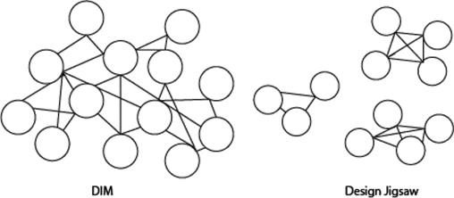
The three main objectives of this prototype are as follows: 1) to develop a prototype that can demonstrate visual information about a piece of design, 2) to link and generate other hints for inspiration, and 3) to generate convergent outcomes within a limited scope so as to reflect the design concept. Compared with the DIM representation (Figure 1 ), it is easier for designers to construct design knowledge from results of the Design Jigsaw, which generates clusters of ideas based on the relationships among the visual hints and concept keywords.
|
|
|
Figure 1. Left: the result of a DIM. Right: the result of the design jigsaw. |
The Design Jigsaw consists of IEs and three types of linking relationships among these IEs. Each IE includes three attributes, namely, Issue (I), Concept (C) and Form (F), which are represented and visualized by keywords, texts and image photos, respectively. By contrast, the DIM includes two kinds of components, namely, IEs and the linking relationships among them. These IEs are assigned to different sub-tasks decomposed from a specific design task, and those IEs with specific design knowledge can then collaborate according to different design situations.
Loosely based on the concepts of IE and linking relationship structure from the DIM, the components of the Design Jigsaw are called idea pieces (IPs) (i.e., the name refers to the “pieces” of a jigsaw game). Each IP records three attributes of the design knowledge [i.e., Issue (I), Concept (C) and Form (F)] in the same way as an IE, along with the linking relationships among I/C/F. In addition, IP further divides C into three properties, Cf (form), Cfu (function) and Cs (structure), based on a depiction of architectural ideas by means of keywords. C and F are the main linking hints of IPs in the Design Jigsaw, that is, the key design knowledge will continue to be constructed until the designer has solved the design problem with an appropriate design jigsaw solution. The three attributes of IP are described below.
- I (Issue): Issue is the keyword representing a design issue in precedents. It describes the design problem, wherein an architect is required to solve the problem by applying his/her knowledge in the concept development stage. For example, one of the main issues in Ronchamp, which was designed by Le Corbusier, was lighting.
- C (Concept): Concept is the keyword representing the design strategy to be adopted for solving a design issue based on the issue factors analysis. In other words, C refers to the conceptual means that are adopted to solve a design issue. There are various authors in the knowledge domain who used the term “strategy” to represent the same idea. Naturally, concept formulation comes after that of issue definition. C is further subdivided into three more specific properties for representing architectural ideas, namely, Cf, Cfu and Cs, which are defined as follows:
- Cf: the keyword representing the concept of form;
- Cfu: the keyword representing the concept of function; and
- Cs: the keyword representing the concept of structure.
- F (Form): Form is often represented using the visualization (e.g., image photos) of IP. Compared with the DIM, the Design Jigsaw uses the geometric features of Form (image) as an initial hint for designers. The geometric features are based on the features that transform an image into a hard contrast black and white picture. According to the features of the white line, the geometric features (Form_geom_feat) are line, curve, surface, and polygon or assembly.
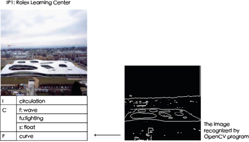
Therefore, the IP of the Rolex Learning Center (2006), designed by the internationally acclaimed Japanese architectural firm SANAA, can be coded in our Design Jigsaw framework as follows: IP [I: circulation, C (Cf: wave, Cfu: lighting, Cs: float), F: curve] (Figure 2 ).
|
|
|
Figure 2. An IP example: the Rolex Learning Center. |
3.2. Relations: links
Linking ideas in the Design Jigsaw are achieved through both divergent and convergent procedures. Linking ideas in the DIM provide a clear divergent procedure. The linking relationships among many relevant IEs are categorized in terms of similarity (SI), contrast (CR), and contingency (CI). Regardless of the synonym issues, contrast (CR) and contingency (CI) still require more semantic definition so that they can be utilized in finding correct links. In the Design Jigsaw, similarity is defined as the direct linking relationship. Contrast and contingency require a reflection on the items received. Therefore, on the bases of DIM links, in the Design Jigsaw, we focused on similarity (SI) (i.e., similar linking relationships) and developed further control strategies over these links to improve the visual effect computational process for convergent procedures. Consequently, all related IPs in the Design Jigsaw were only linked through similarity (SI) linking mechanisms. Furthermore, similarity linking focused on linking other IPs with similar C (Concept). We thus developed control strategies over the concept of IPs. These are described below, along with the linking mechanisms of the Design Jigsaw.
- Cf linking (cf→): Here, there are similar annotations of F between two IPs, and the relationship is recorded as IP cf→IP. There are three linking weights dependent on cf→ linking numbers. The maximum linked IP numbers is cf→1, then cf→2, and finally cf→3 seriatim.
- Cfu linking (cfu→): Here, there are similar annotations of function between two IPs, and the relationship is recorded as IP cfu→IP. There are three linking weights dependent on cfu→ linking numbers. The maximum linked IP numbers is cfu→1, then cfu→2, and finally cfu→3 seriatim.
- Cs linking (cs→): There are similar annotations of structure between two IPs. The relationship is recorded as IP cs→IP. There are three linking weights dependent on cs→ linking numbers. The maximum linked IP numbers is cs→1, then cs→2, and finally cs→3 seriatim.
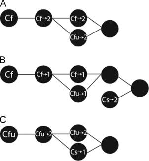
The similarity in the Cf linking relationship exemplified in the IPs in the Design Jigsaw is shown in Figure 3 . The IPs are linked by different Si relationships, such as cf→, cfu→, and cs→. The number of links decides the linked weights.
|
|
|
Figure 3. The linking relationships of IPs. |
3.3. Control strategies: grouping
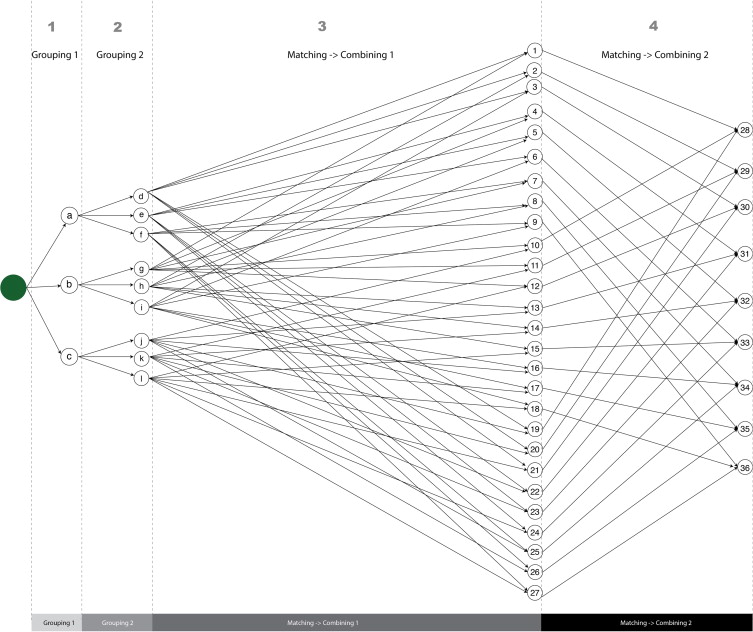
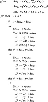
Control strategies are developed in the computational design jigsaw process. Here, the designer can apply different control strategies for restraining the amount of IPs that appear. Basically, there are four levels of control strategies applied (Figure 4 ): two for grouping and two for matching→combining.
|
|
|
Figure 4. The levels and control strategies of the design jigsaw. |
As shown in Figure 4 , each node is a new outcome generated by control strategies in the last level. The nodes in Grouping 1 and Grouping 2 are designated as “a ” to “l,” corresponding to a total of 12 nodes, in these two levels. The 36 nodes coded from 1 to 36, represent the outcome of the levels matching→combining 1 and matching→combining 2. The links are the relationships formed by the linking weights of different properties.
The control strategies of assembling are implemented as a rule-based system in the Design Jigsaw model. The four control sequence process mechanisms are described in the following subsections. Meanwhile, using the figure above, the grouping control strategies are described below.
- Grouping 1: This level groups the IPs into three groups using the concept descriptions designated by the keywords Cf, Cfu, and Cs. The Grouping 1 level generates three groups from the different attributes of IPs linked by SI relationships: node a, node b, and node c. Node a is a Cf group within cf→, node b is a Cfu group within cfu→, and node c is a Cs group within cs→.
- Grouping 2: This level groups the IPs again by means of the linking weights of Cf, Cfu, and Cs, thus producing nine groups. The maximum IP numbers with similar keywords is assigned to weight →1, the weight of the second IP numbers with similar keywords is recorded as →2, and the weight of the third IP numbers with similar keywords is assigned as →3. Consequently, the nine groups are cf→1 group at node d, cf→2 group at node e, cf→3 group at node f, cfu→1 group at node g, cfu→2 group at node h, cfu→3 group at node i, cs→1 group at node j, cs→2 group at node k, and cs→3 group at node l.
3.4. Control strategies: matching and combining
All selected IPs were grouped in nine groups either as a pair or as parts of a group with diverse concept attributes. The matching and combining mechanisms below allow users to identify the linked IPs into possible interested groups. With a reduced number, users can better manage and select the IPs for its design inspiration. These two control strategies are shown below.
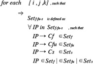
Matching and Combining 1: In this step, a new outcome is matched with two similar concepts and then combined through the weights used to assemble a converged linking network in the Grouping 2 step. This strategy can generate 27 different matching and combination nodes (nodes 1–27). The rules of matching and combining 1 are shown below as Figure 6 .
|
|
|
Figure 5. Process of the design jigsaw. |
|
|
|
Figure 6. rule1_graph. |
Matching and Combining 2: In this step, a new group is matched with three similar concepts and then combined through the weights used to assemble a converged linking network in the matching and combining 1 step. This strategy can generate nine different matching and combination outcomes (nodes 28–36). The rules of matching and combining 2 are shown as Figure 7 .
|
|
|
Figure 7. rule2_graph. |
4. Design experiment
In order to understand the control strategies of the proposed Design Jigsaw framework, we created a prototype for the purpose of experimentation. We then conducted a design experiment for prototype testing. Three key aspects of the experiment are described in this section, including the procedural description of the system, the participants and work environments, and the analysis of the experimental data collected.
4.1. Procedural description of the system
The system consists of six steps as described below.
- Selecting an initial IP: This involved importing an IP as the starting point of information flow.
- Retrieving IPs with Form association with the initial IP from the repository: Here, the IPs were selected from the IP repository by matching the geometrical features of the Form of the initial IP. This step was implemented in order to identify hints from the scattered jigsaw pieces, which could help in retrieving similar IPs with forms (i.e., features) that match those of the initial IP. We used the IP repository, which stored data about IPs.
- Grouping retrieved IPs into three groups: After retrieving, we then grouped those with linked IPs from the retrieved IPs from Step 2 into three groups, namely, the Cf, Cfu, and Cs groups. Grouping was done using the Grouping 2 level control strategy.
- Secondary grouping to create nine groups: Here, each linked network in one group from Step 3 was ordered by means of the weights in the network. Those with higher number weights were grouped in the secondary grouping. Only the top three groups in the secondary grouping were collected from the three different groups. Therefore, after secondary grouping, we created nine groups that contained a linked network in each group.
- Pair matching and combining from secondary grouping: To construct convergent idea concepts by matching and combining different Concept attributes, two properties were matched and combined. These were as follows: Cf matched and combined with Cfu, Cfu matched and combined with Cs, and Cs matched and combined with Cf by means of the weights of the IP numbers. For example, when some IPs matched not only the Cf(cf →1) group but also the Cfu(cfu→1) group, these could be combined to create a new outcome. Pair matching and combining nine groups generated from the last step produced 27 outcomes.
- Triple matching and combining from secondary grouping: Here, matching and combining were performed again to create a triple layer by selecting Cf, which was matched and combined with Cs. For example, when some IPs matched the keywords of Cf(cf →1), Cfu(cfu →1), and Cs(cs →1), they led to triple matching and combining and a total of nine outcomes.
4.2. The participants and work environment
The design subject was an information center located at Danhsui Harbor. The programs were ticket booth, waiting area, and information bulletin board. The participants (A, B, C) of this study were three third year college students who majored in Architecture. As they were in their junior year, they were considered to have already undertaken basic training in architecture. They were required to perform two simulations in order to reify and compare the control strategies of the Design Jigsaw system. The work setting for the prototyping was a simple design jigsaw game developed using paper cards.
4.3. Experimental data analysis
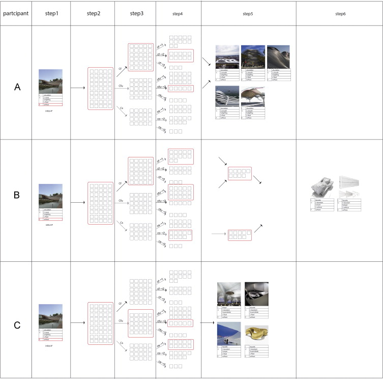
The IPs and processes of each participant were collected to observe the details of the control strategies in the prototype. The initial IP selected by the participants in Step 1 was based on a fixed Form_geom_feature (surface). A total of 45 IPs then underwent secondary grouping. Each concept was matched and assigned into one of three groups: Cf, Cfu, or Cs (Step 3). Each group comprised a single network with 3–15 linked IPs. Once grouped, participants made their choices. Participants A and B chose Cf, while participant C selected the Cfu group. The results of the control strategies employed by the different participants in successive steps are shown below (Table 1 ).
|
|
|
Table 1. The results of the experiment. |
After completing Step 3, participant A selected the cf→2 group, which comprised 11 IPs and was based on the conceptual keyword “smooth.” Matching and combining mechanisms compared selected IPs with other cfu→ and cs→ in six combinations. Next, Cf(cf→2) and Cfu(cfu→2) were selected in Step 5. Here, 16 IPs (11 from cf→2 and 5 from cfu→2) were matched and combined into five IPs.
In Step 4, participant B selected the cf→1 group, which comprise 12 IPs and was based on the conceptual keyword “transform.” Matching and combining mechanisms compared selected IPs with other cfu→ and cs→ in six combinations. In Step 5, cf→1, cfu→1, and cs→2 were selected. In Step 6, 37 IPs (12 from cf→1, 15 from cfu→1, and 10 from cs→2) were matched and combined into two IPs.
Different from other participants, participant C selected the Cf group in Step 3. This group was based on the conceptual keyword “penetrate.” There were five IPs from cf→2 and 10 from cf→1. These IPs were matched and combined into two IPs in Step 5. The control strategies of the Design Jigsaw of this experiment are depicted in Figure 5 .
We gained several insights from the observations. First, the designer can explore more ideas if the system starts from grouping the visual features. Second, by matching–combining different aspects of C (i.e., Cf/Cfu/Cs), the ideas are easier to classify and retrieve. Third, C is an important stage, in which designers can explore diverse connections and directions as well as gain the ability to be convergent while working on a manageable set of design ideas.
5. Conclusion
Based on the simple concept of representing the selection process of design ideas in the early phases of designing as a kind of jigsaw puzzle-solving game, we explored a computational design method of methodological mapping (jigsaw) and consequential analysis (Design Jigsaw system prototype), in order to create associations among varied types of information at different levels in the design information hierarchy. The Design Jigsaw system is rooted in finding a manageable set of IPs from interlinked idea maps. Therefore, most of the mechanisms (i.e., representation, components, and the control mechanisms involved in these components) we developed aimed at modeling the observations to be gained from the rule-based design process on which design decisions can be made.
Following the outcomes of the experiment, the results are reasonable and relevant for further investigation. However, this research only presents partial characteristics of the Design Jigsaw system. Apart from further defining the relevant relationships, a more in-depth exploration to identify better matching algorithms (rather than the simple keyword matching) should be conducted. Doing so can lead to a more effective method by which to comprehensively reify the effectiveness of the grouping/matching-combining algorithms.
References
- 1 Chang, T.W. Supporting Design Learning with Design Puzzles – Some Observations of On-line Learning with Design Puzzles, in Design & Decision Support Systems(DDSS'04) in Architecture and Urban Planning, Dordrecht, Kluwer Academic Publishers, Netherlands, 2004, pp. 293–307
- Cheng and Chang, 2007 Cheng, Y.B., Chang, T.W., Solving design puzzle with physical interaction – a collage table implementation. In: Proceedings of the 12th Conference on Computer-Aided Architectural Design Research in Asia (CAADRIA 2007), Nanjing, China, April 19–22, 2007, pp. 11–18.
- Gaver and Bowers, 2012 B. Gaver, J. Bowers; Annotated portfolios; Interactions, 19 (4) (2012), pp. 40–49
- Lai and Chang, 2006 I.C. Lai, T.W. Chang; A distributed linking system for supporting idea association in the conceptual design stage; Des. Stud., 27 (6) (2006), pp. 685–710
- Lo et al., 2010 Lo, C.H., Lai, I.C., Chang, T.W., 2010. Playing jigsaw: finding the underlying structure of combining ideas within design productive process. In: Proceedings of the Conference on Computer-Aided Architectural Design Research in Asia (CAADRIA 2010), Hong Kong, pp. 371–380.
- Lo et al., 2011 Lo, C.H., Lai, I.C., Chang, T.W., 2011. A is b, displacement: exploring linking patterns within metaphor in the design process. In: Proceedings of the Conference on Computer-Aided Architectural Design Research in Asia (CAADRIA 2011), Newcastle, Australia.
- Oxman and Oxman, 1993 Oxman, R. And Oxman, R. 1993. Precedents: memory structure in design case libraries, In: Flemming, U., Wyk, S. (Eds.), Proceedings of the Fifth International Conference on Computer-Aided Architectural Design Futures (CAAD Futures’93), pp. 273–287.
- Oxman, 1994 R.E. Oxman; Precedents in design: a computational model for the organization of precedent knowledge; Des. Stud., 15 (2) (1994), pp. 117–134
- Tunçer, 2009 Tunçer, B., 2009. The Architectural Information Map: Semantic Modeling in Conceptual Architectural Design (Ph.D. dissertation). Delft University of Technology, Delft, The Netherlands.
- Ulrich and Eppinger, 1995 K.T. Ulrich, S.D. Eppinger; Product Design and Development; McGraw-Hill, New York, USA (1995)
- Yang et al., 2004 Yang, L.C., Lin, C.C., Chang, T.W., Chen, S.C., 2004. Exploring visual information with puzzle rule – a design collage approach. In: Proceedings of the International Symposium on Automation and Robotics in Construction (ISARC 2004), Jeju Island, Korea.
- 1 Zouaq, A., Nkambou, R., Frasson, C., 2007. An integrated approach for automatic aggregation of learning knowledge object, Interdisciplinary Journal of Knowledge and Learning Objects, vol. 3, p. 135-162
Document information
Published on 12/05/17
Submitted on 12/05/17
Licence: Other
Share this document
Keywords
claim authorship
Are you one of the authors of this document?
