Abstract
The Adaptive Solar Facade (ASF) is a modular, highly integrated dynamic building facade.The energetic behavior as well as the architectural expression of the facade can be controlled with high spatio-temporal resolution through individually addressable modules. We present the general design process, the current mechanical design, and simulation results on photovoltaic power production and building energy consumption. We introduce the controller concept and show results on solar tracking as well as user interaction. Lastly, we present our current and planned prototypes.
Keywords
Dynamic facade ; BIPV ; Facade engineering ; Photovoltaics ; Responsive architecture
1. Introduction
Over a third of the anthropogenic greenhouse gas (GHG) emissions stem from the operation of buildings (heating, cooling and electricity), due to their fossil fuel based operation (Lucon and Ürge-Vorsatz, 2014 ). Therefore, the existing building stock offers a great potential for CO2 mitigation. In fact, the EU aims for all newly constructed buildings to have close to zero net energy consumption by 2020 (EU, 2010 ). To achieve this, incorporating renewable energy generation, such as photovoltaic (PV) systems, into buildings has been recognized as a viable path. Building integrated photovoltaic (BIPV) systems are typically rooftop installations owing to the relatively heavy weight structure of traditional silicon-based PV modules (Frontini et al., 2015 ). In addition to this bulkiness, while alternatives are slowly emerging, traditional PV modules still suffer from the monotonic blue color, which makes individual building integration challenging. Novel developments, such as organic solar cells, offer lightweightness and color variations and have been successfully applied in large scale buildings as, e.g., windows. However, the significantly low efficiency does not make them yet a viable approach for efficient solar power generation (Barraud, 2013 ).
On the other hand, thin-film PV modules, such as Cu(In, Ga)Se2 (CIGS), offer the advantage of flexible, curved, shapes and a lightweight structure when compared to the traditional modules, which come at the price of lower energy conversion efficiencies. However, recent research results have demonstrated that thin-film PV modules can also attain efficiencies similar to the traditional modules (Reinhard et al., 2013 ). In addition, from an economical perspective, the price per watt-peak of both systems have become comparable. Therefore, thin-film PV systems have become a powerful technology for BIPV (Kaelin et al., 2004 and Chen et al., 2014 ).
The lightweight structure of thin-film modules allows it to consider their integration into the building envelope. Although such facade PV systems receive less irradiation than rooftop and ground installations, they offer lower diurnal and seasonal variations, and can therefore substantially contribute to local electricity generation.Integrating BIPV with conventional building components, such as shading systems, can further lower costs and environmental impacts (Perez et al., 2012 ).
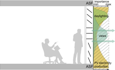
From an architectural perspective, the building envelope, or facade, is in essence the public face of a building, and has therefore a large impact on the perception of the building. From an energetic perspective, the envelope acts as a buffer or mediator between the interior and the exterior environment (see Fig. 1 ). The envelope can mitigate solar insolation, thereby offering reductions in heating/cooling loads, and improve distribution of daylight. Therefore, integrating PV modules into a dynamic shading system offers the possibility to fine tune the different functions, generate electricity, and balance energetic performance with architectural expression.
|
|
|
Fig. 1. The facade acts as mediator between the interior and the exterior environment and fulfills various functions. Modified from Jakica and Zanelli (2014) .
|
In this paper, we present our current progress on the Adaptive Solar Facade (ASF), a modular highly integrated dynamic building facade.The energetic behavior as well as the architectural expression of the facade can be controlled with high spatio-temporal resolution through individually addressable modules. The novelty of the ASF, compared to other dynamic facade systems,lies in the complexity of the integration of the individual functions, resulting in multi-dimensional functionalities.
The remainder of the paper is organized as follows. The next section introduces the architectural concept of the ASF. In Section 3 , we present the mechanical design, as well as the controller concept. We discuss our numerical analysis methods and results in Section 4 . Our current prototypes are introduced in Section 5 . Finally, Section 6 concludes the paper.
2. Architectural concept
The field of dynamic facades as sustainable building elements is in its infancy. However, as discussed by Velasco et al. (2015) , the field is growing rapidly due to the requirement for better environmental performance of the building stock, and the recent rise of computational tools and electronics for control. Dynamic facades have the potential to add to the architectural expression of a building by visualizing the changeable aspects of the environment (Meagher, 2015 ).
Capitalizing on the advantages of flexible thin film modules, Kenney & Violich Architecture (kvarch.net) developed The Soft House . It features a PV-embedded textile shading system consisting of individually movable stripes. The textile stripes can be raised and twisted using DC motors to maximize for various functions such as shading, solar gains, or PV generation.
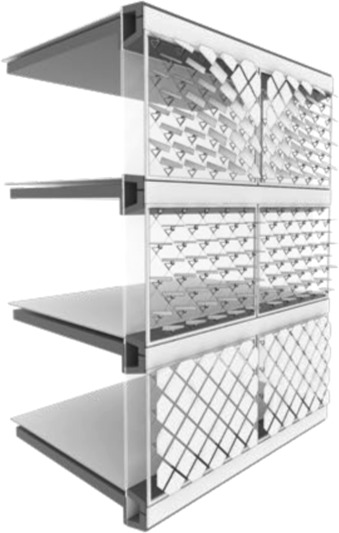
The concept of the Adaptive Solar Facade (ASF) has been introduced in Rossi et al. (2012) . We review it here for completeness. The basic element of the ASF is the dynamic, multifunctional module. It provides shading, electricity production, as well as daylight distribution. The module can act autonomously, but it can also be clustered into small groups. Likewise, as shown in Fig. 2 , groups of clustered modules can relate to a window or particular interior spaces. As we will detail below, the conceptual differences to the Soft House approach is that first, for the ASF we are experimenting with novel low-cost actuators, and second, we explore a fully modular approach and increase the granularity of the facade.
|
|
|
Fig. 2. Modules on a building facade, mounted in frames on a cable net structure within the shading layer of the facade.
|
As the components can move independently of each other, and in response to varying internal and external environmental influences, complex surface patterns can emerge without the need to design and fabricate complex geometries (see Fig. 3 ). The complexity of the system is generated through its behavior rather than through non-standard components. Even with a simple tiling pattern many potential variations are possible.
|
|
|
Fig. 3. Abstract representation of possible emergent module patterns of the ASF.
|
The tiling pattern of the modules is not confined to a predetermined size or geometry. Solar thin film manufacturers offer the production of custom geometries, and an increasing number of colors and degrees of translucency, which widens the design palette open to architects. The diamond shaped modules in Fig. 2 and Fig. 3 are due to our current prototype designs (see Section 3 ). Other shapes are conceivable, especially considering that the shape of the PV module and the shading panel do not have to coincide.
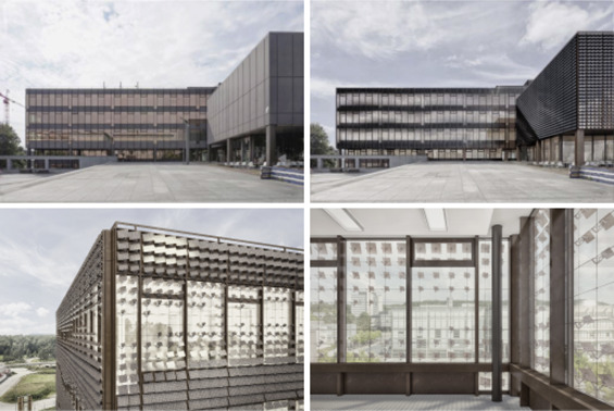
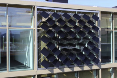
Another variation of the ASF is shown in the photomontage of Fig. 4 , where it is applied as a retrofit measure to an existing building. Here, the modules are squares to follow the design of the building. The demonstrated design applications represent only a fraction of the possibilities for adaptive solar facades on buildings in general. In its current status, the ASF can be summarized architecturally as a smart facade element that can become a platform for energy efficiency, visual comfort, daylight distribution as well as branding and image.
|
|
|
Fig. 4. The Adaptive Solar Facade as a retrofit measure on the HIL building of ETH Zürich. Top left: Photograph of the building. Top right: Photomontage of the building with the ASF. Bottom left: Close-up view. Bottom right: View from the inside. (Images by Christian Studerus.)
|
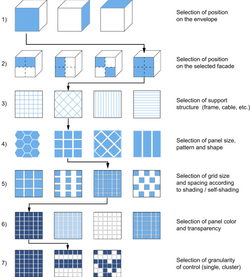
In Fig. 5 we illustrate the general design process for the ASF. Steps (1) and (2) relate to the positioning of the ASF on the building and on the facade. After this, in step (3), a suitable support structure has to be defined, which can utilize existing structure on the building, or an added structure, e.g., a frame and cable-net solution as is the case for our prototypes. Steps (4)–(6) define the basic visual expression of the ASF by selecting panel shapes and patterns, their relative positions, as well as materials (colors and transparency). Finally, in step (7), the control granularity of the ASF is chosen, by defining whether all modules move together, or in bands, or individually. In our prototypes, we opted for the latter.
|
|
|
Fig. 5. Design process of the ASF. See main text for explanations. The arrows follow one possible design.
|
3. Design
3.1. Mechanical
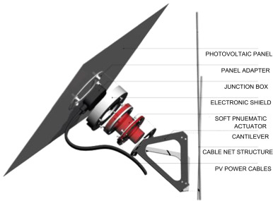
The current design of the ASF has four key elements: The shading panel consisting of 0.8 mm thick aluminum substrate for the thin-film PV module, the soft-pneumatic actuator, the cantilever, and the supporting frame and cable net (see Fig. 6 and Fig. 7 ). The module has a total weight of 800 g. In the following we detail the design considerations for the actuator, the cantilever and the cable net.
|
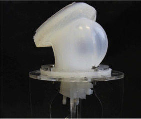
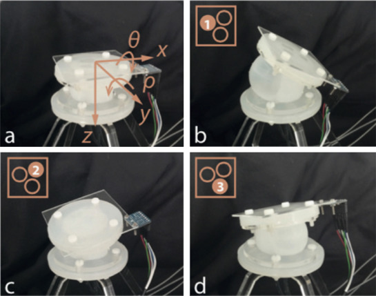
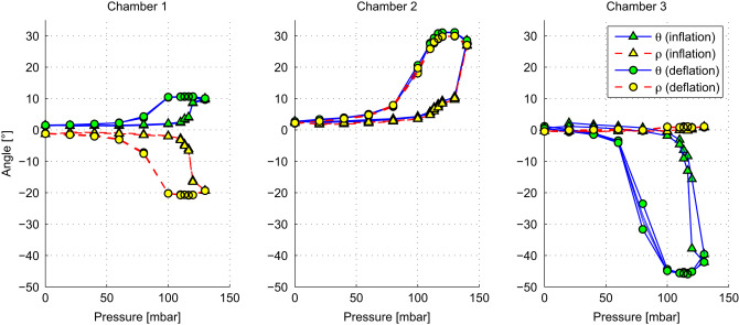
Soft pneumatic actuator : The soft pneumatic actuator is made from elastic materials, e.g., silicone rubber, and energized using compressed air. Fig. 8 presents the current prototype of the soft pneumatic actuator developed specifically for the ASF. The actuators contain three inflatable chambers, and are, as shown in Fig. 9 , capable of orienting a PV cell along two axes (Svetozarevic et al., 2014 ). The pressure-deflection characteristics of all three chambers during inflation and deflation are depicted in Fig. 10 .
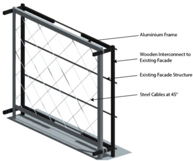
Frame and cable net : The cable net, spanning a stainless steel frame, forms the supporting structure of the ASF ( Fig. 7 ). The frame and the cable net were designed to withstand an approximated wind load of 500 N per panel (corresponding to a windspeed of ≈180 km/h). The frame consists of two vertical U-channel profiles and two horizontal L profiles. Further details of the properties are shown in Table 1 .
| ||||||||||||||||||||||||||||||||||||||
|
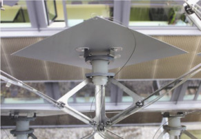
Cantilever : The offset provided by the cantilever enables the PV panel to rotate in all necessary directions without interfering with the cable-net structure.The cantilever is tilted to 45° as the actuator can achieve a rotation of . This enables the panel to attain a fully open and fully closed position. The current design shown in Fig. 11 is a double bent cantilever manufactured from laser cut stainless steel. It minimizes the obstruction of the occupants׳ view, and remains lightweight while simultaneously being sufficiently strong to carry the PV module and withstand the elements.
|
|
|
|
Fig. 6. Current facade module.
|
|
|
|
Fig. 7. Rendering of the frame and cable-net.
|
3.2. Control system
The objective of the ASF is to create a comfortable thermal and visual environment, fulfilling the requirements of the user for shading, temperature and light levels. At the same time, power should be generated through the PV cells whenever doing so does not conflict with the desires of the user.
As we have described in Rossi et al. (2012) , we do not envision a high level controller to coordinate the interaction between the lighting, shading, and power generation. Rather, we investigate if, and if so then how, the ASF can adapt to its environment, and in particular to its user.
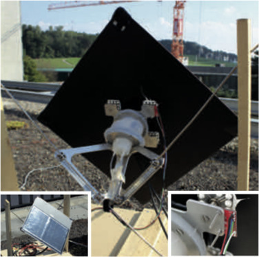
In our current implementation, the modules of the ASF can perform two-axis solar tracking, i.e., orient themselves toward the sun. This is a key component for maximum power production of the ASF. To achieve this, an inertial measurement unit (IMU 9150 from InvenSense) that measures the azmimuth and altitude angles is attached to the panel (see Fig. 12 ). The reference positions for the sun for a given date/time are generated using the DIVA plugin for Rhino (Jakubiec and Reinhart, 2011 ).
|
|
|
Fig. 12. Experimental setup for solar tracking. Top: Back view on the ASF module. Bottom left: Front view on the module with the thin-film solar module. Bottom right: Sparkfun breadboard with IMU.
|
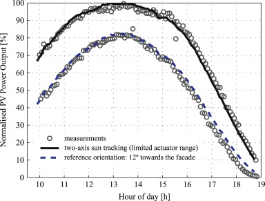
The results of one solar tracking experiment with one module are shown in Fig. 13 . The experiment is set on the roof of authors׳ office building in Zurich (47°24′N, 8°30′E) and was performed on a clear day (August 31, 2015). The DC power output at maximum power point (MPP) of the thin-film CIGS module was recorded, while the ASF module position was adjusted every 5 min. In addition, we measured the power output at the reference position. Ideally, the reference position would be aligned with the building walls (0°) and oriented to the south. However, due to the actuator limits, we could only achieve 12°.
Fig. 13.
Power production during solar tracking experiment on August 31, 2015.
We calculated the PV power output using a model that takes into account the three components, i.e., beam, diffuse sky, and ground reflected radiation (Häberlin, 2012 ). In addition, we take into account the actuator range, the active PV area and its electrical conversion efficiency. As seen in Fig. 13 , the experimental results correspond very well to the model predictions. The measured gain due to solar tracking was 36% on this particular day. This demonstrates successful solar tracking with the ASF module.
As for the user interaction with the ASF, note that typically users do not adjust their blinds more than once per day (Gunay et al., 2013 ). This low interaction means that there is a flexibility for automatic control with the goal of energy optimization, as long as it does not interfere with the person׳s wishes, and the movement of the modules is not distracting.
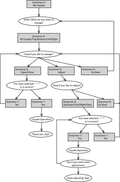
At the same time, the way of interacting with the ASF must be intuitive and not overwhelming, especially in view of the many potential configurations, and a simple override mechanism must be provided. As a first approach, we implemented a voice-based interaction mechanism on our laboratory scale prototype (see Section 5.1 ) using the Arduino (www.arduino.cc ) and EasyVR (www.veear.eu ) hardware. This allowed us to define simple commands (open/close/adjust) bound to specific locations on the ASF (left, right, top, and bottom), and execute a specific program once the voice command has been identified. Fig. 14 shows the flowchart of the program. It listens for the keyword ‘My Facade’, enters upon detecting it into the control logic, and executes the appropriate actions.
|
|
|
Fig. 14. Interaction diagram. Rectangles: possible user inputs (grammars). Ellipses: ASF response/action.
|
The EasyVR hardware does not require training of the user for voice recognition. In an initial test, amongst 13 research group members, we achieved an average recognition rate of 97.1% amongst the native English speakers, and 91.2% for the non-native English speakers. This success proves the viability of the voice-based approach.
In a further experiment, we evaluated the interaction of the users with the facade based on success or failure in operating the facade. To simulate the intuitiveness, the users were only given a brief verbal introduction to the system. We considered as success when the user achieved the desired operation, and as failure otherwise. The 13 users completed a total of 68 trial runs, and achieved an average success rate of 64%. These results are encouraging, but also show that more work is robustequired to achieve a robust interaction.
As for the user acceptance, we have received anecdotal feedback that the interface was in general relatively simple to learn and operate. However, a more natural command process would be preferable over our implemented stepwise dialog. While most of the users agreed that voice control is a feasible approach for the ASF, there were also some with strong preferences towards a mechanical interaction, e.g., via switches. In other words, redundant interaction mechanisms need to be provided.
4. Numerical analysis
To analyze the ASF, we have developed two simulation environments using the Rhinoceros 3D (www.rhino3d.com ) software and its Grasshopper (www.grasshopper3d.com ) plugin. In the first, we used a simplified design version of the ASF to investigate the influence on the energy demand (heating, cooling, and electricity) of a hypothetical one zone office room. In the second, we use a more detailed model to analyze the solar electricity production throughout the year. In the following, we detail our findings.
4.1. Energy demand savings
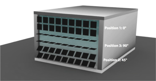
The analysis is done for a south facing office similar to the room in the House of Natural Resources (HoNR) building where the ASF is first realized (see Section 5.2 ). The modeled room is shown in Fig. 15 . The modules of the ASF are modeled as 400×400 mm panels. The panels are grouped into three bands where each band can exist in a fully open (90°), fully closed (0°), and slanted (45°) state on a horizontal axis. On the vertical axis all the panels can move from 90° to −90° in steps of 15°.
|
|
|
Fig. 15. The studied room with the Adaptive Solar Facade attached. In the shown configuration, the panels are at 0° on the vertical axis, and 0°, 90°, and 45° on the horizontal axis from top to bottom, respectively.
|
Each of the resulting 324 possible ASF configurations are analyzed in Energy Plus using a single zone thermal analysis with hourly time steps over a one year period. A summary of simulation parameters can be found in Table 2 . Then, the results were processed in MATLAB to determine the optimal configuration for each hour of the year.
| Office envelope | Roof/floor/walls: adiabatic |
|---|---|
| Window: double glazed LoE glass | |
| Infiltration: 0.5 exchanges/hours | |
| Thermal set-points | Heating: 22° |
| Cooling: 26° | |
| Lighting | Set-point: 11.8 W/m2 |
| Control: 300lxthreshold | |
| Occupancy | Office: weekdays from 8:00 to 18:00 |
| Persons: 0.1 people/m2 | |
| Adaptive Solar Facade | Solar reflectance: 0.5 |
| Visible reflectance: 0.5 | |
| Weather file | Geneva, Switzerland (067000-IWEC) |
To analyze the energy savings, we convert the simulated net energy demand for heating, cooling, and lighting to the end electricity demand for the office based in Switzerland. We assume a heat pump with a coefficient of performance (COP) of 5 to regulate the office temperature. The office is cooled using incoming district water, therefore only pumping electricity is taken into account. The room is assumed to be illuminated with 113 W LED lighting.
The energy consumption and savings of the ASF is compared to two reference configurations: (1) a case without shading and (2) a standard louver system with blinds fixed at 45°. The results for the net energy demand and the total electricity demand are shown in Table 3 and Table 4 , respectively.
| (1) No shading | (2) Louvers at 45° | ASF | % savings comp. to (1) | % savings comp. to (2) | |
|---|---|---|---|---|---|
| Heating (GJ) | 4.64 | 5.29 | 4.70 | −1 | 11 |
| Lighting (GJ) | 1.56 | 1.65 | 1.60 | −3 | 3 |
| Cooling (GJ) | 13.5 | 4.53 | 2.39 | 82 | 47 |
| Total (GJ) | 19.7 | 11.5 | 8.69 | 56 | 24 |
| Louvers at 45° | ASF | Savings (absolute) | Savings (%) | |
|---|---|---|---|---|
| Heating (kW h) | 301.2 | 267.4 | 33.0 | 11 |
| LED lighting (kW h) | 124.9 | 121.1 | 3.78 | 22 |
| Cooling pump (kW h) | 4.17 | 3.24 | 0.9 | 3.0 |
| Total (kW h) | 430 | 391.8 | 38.4 | 8.9 |
| kgCO2 -eq (EU grid mix) | 171.7 | 156.3 | 15.3 | 8.9 |
The ASF achieves total energy savings of 56% compared to the no shading case and 25% compared to the fixed louvers case. Table 4 shows a reduction in the electricity consumption compared to the fixed louvers case by 8.9%, which also corresponds to a CO2 offset of 15.3 kg CO2 -eq per year based on the EU grid mix.
4.2. PV system design
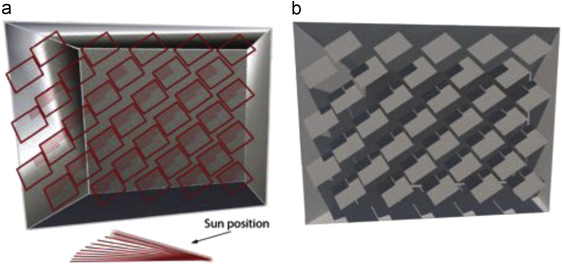
The modules of the ASF are equipped with highly efficient and lightweight thin-film CIGS PV modules. In order to estimate the electricity production from the ASF and to optimize the system configuration, we developed an integrated framework combining high-resolution 3D shading calculation and electrical modeling. In the first step, the appearance and mutual shading between an array of dynamic PV modules is simulated. Based on the building geometry, the horizon contour line, and the module geometry, we determine for each module and sun position the following important variables: the shadow shape, orientation towards the sun, sky view factor, and visibility of reflecting elements. This process is iterated over time. The results are stored in data files at the desired spatial and temporal resolution. Potentially various module and facade geometries can be evaluated. As an example, Fig. 16 shows the calculation of mutual shading of the modules for a specific facade layout and sun position. To verify the calculation method, the shading pattern is compared to a physical based rendering as shown in Fig. 16 b.
|
|
|
Fig. 16. (a) Module shading calculated within Rhino/Grasshopper for a specific sun position. (b) Corresponding rendering using the LuxRender software.
|
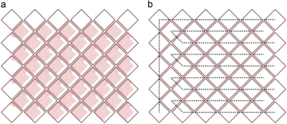
For further analysis of the electrical performance, the shading pattern and solar irradiance are coupled with an electrical model, which calculates the characteristic current–voltage curves of PV modules and their interconnection as a function of time. We optimize the electrical design of the system by modeling the energy yield for different PV cell orientations and placement of bypass diodes. Knowledge of the shading pattern is also important for efficient interconnection of modules, as only modules with similar irradiance should be connected in strings to minimize electrical mismatch losses. An example of a possible string layout considering the shading pattern is shown in Fig. 17 . Note that the optimal electrical configuration in terms of PV cell orientation and string configuration depends on the facade orientation, module arrangement and control strategy.
|
|
|
Fig. 17. Shading pattern (a) and possible module string connection (b) for a specific sun position.
|
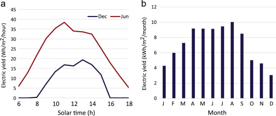
The modeling framework helps us to predict electricity generation of the facade system as well as to plan PV system components and building integration. Fig. 18 shows the typical daily and monthly electricity generation profile per square meter of active PV module area for a south facing facade located in Zurich, Switzerland. Note that electricity generation of the facade PV system is relatively high in winter compared to conventional roof mounted PV systems and as such reaches a better match with building electric loads.
|
|
|
Fig. 18. (a) Typical electricity generation over one day in December and June for a south facing facade per module area using 2-axis tracking. (b) Average monthly electricity generation.
|
5. Prototypes
5.1. Laboratory scale: proof-of-concept
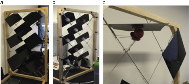
The first prototype, shown in Fig. 19 , consists of eight panels made of plastic without a photovoltaic module. It was mainly constructed to test the functionality of the soft pneumatic actuators. The actuators can rotate the panel in two degrees of freedom at an angle . The actuators are attached via laser cut plexiglas (PMMA) cantilevers to the steel cable net support, see Fig. 19 c.
|
|
|
Fig. 19. Proof of concept with 8 panels on a wooden frame. (a) Front view, (b) rear view exposing the actuators and cable net, and (c) open and closed configurations.
|
5.2. Building scale: ETH House of Natural Resources
Our first full-scale proof of concept prototype, shown in Fig. 20 and Fig. 21 , was constructed on the House of Natural Resources Building (HoNR) on the ETH Honggerberg campus (www.honr.ethz.ch ). The building was inaugurated in June 2015, and showcases advances in sustainable building technology, e.g., post-tensioned timber frame using hardwood, timber–concrete composite slab using beech wood plates, biaxial timber slab, and the ASF.
|
|
|
Fig. 20. Building scale ASF prototype on the House of Natural Resources (HoNR).
|
|
|
|
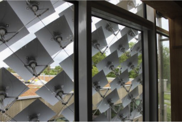
Fig. 21. Inside view on the ASF.
|
The ASF prototype is 3.9×3.2 m and contains 50 individually addressable modules. A movie of its construction and operation is available on the website of the authors (http://systems.arch.ethz.ch ). The ASF was installed in front of a south facing office. To monitor the thermal comfort, temperature, humidity and illuminance sensors have been deployed inside the office. In addition, the adjacent and identical office with a conventional, fabric based, shading system is monitored. The objectives are to validate the numerical models, compare the thermal and electrical performance of the ASF to the standard office, and quantify the differences. Furthermore, feedback from the occupants will also be gathered through behavioral studies.
5.3. Outlook: HiLo/NEST
The next prototypes will be installed in the HiLo (High performance–Low energy) research and innovation unit of NEST (Next Evolution of Sustainable building Technologies, nest.empa.ch). NEST is a dynamic, modular research and demonstration platform for advanced and innovative building technologies in Switzerland.
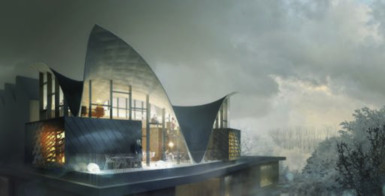
The HiLo unit, shown in Fig. 22 , is planned as a duplex penthouse apartment for visiting scientists, and will showcase ultra-lightweight construction as well as smart and adaptive building systems. The Adaptive Solar Facade will be one of four core innovations exhibited in HiLo, the other three being:
- an integrated, thin shell roof (Veenendaal and Block, 2014 ),
- a funicular floor system (López et al., 2014 ), and
- an occupant centered control system (Nagy et al., 2014 and Nagy et al., 2015 ).
|
|
|
Fig. 22. The HiLo module at NEST/EMPA will feature two adaptive solar facades.
|
In fact, two ASFs will be installed at HiLo on different facades (south and south-west) in front of the two bedroom windows. This will allow us to study the individual control and interactions of the occupants with the facades, in a residential setting – as opposed to the ASF on the HoNR as an office setting. The NEST backbone was completed in September, 2015, and the construction of the HiLo module is scheduled to start in mid-2016.
6. Discussion and conclusions
In this paper, we presented our progress in the development of the Adaptive Solar Facade. The architectural concept and the mechanical design of the proof-of-concept prototypes were discussed. The modular approach allows for simple design of the individual module, while the complexity in behavior is handled through the control system. This, combined with a lightweight support structure enables simple and straightforward integration of the ASF on various facades, making it a viable solution for large scale building integrated photovoltaics.
Using numerical simulations, we showed the energy savings potential. For our particular setup, we achieved total energy savings of 25%. Finally, we discussed solar electricity generation under the constraint of self-shading and demonstrated the advantage of solar tracking.
Related to the financial aspects of the ASF, it is clear that in a commercial real-world application the goal will be to balance the energy and emission savings with the investment and operational costs. This economic aspect remains to be further investigated. The presented work is a research prototype aiming at exploring the technical possibilities, potentials and architectural implications of a modular, dynamic farcade. We believe that the employed components, i.e., soft pneumatic actuators, lightweight thin-film photovoltaic modules, reduced number of electrical components, etc., lay a solid foundation to further design and optimize an economically viable system or product line without compromising their advantages. A range of products are conceivable, from a basic system where all modules perform the same action, to complex modular systems with self-learning capabilities and voice control.
Possible further research directions are to analyze the effects of the facade in different application scenarios and climates. If the facade were to be applied in a hot climate, e.g., Spain, then we expect even larger energy savings compared to the base case of a moderate climate as discussed in this paper. The application of the facade in two real-world living labs, the ETH House of Natural Resources and HiLo, will allow the validation of the simulation using measurements and, moreover, the conduction of thermal and lighting comfort analysis to complement the energy savings and renewable energy generation, respectively. Finally, focus group studies should be conducted in order to determine the subjective design potentials of the ASF for individual designers.
Acknowledgments
The authors would like to acknowledge the HiLo and HoNR project members. Supermanoeuvre (Sydney, Australia), ZJA Zwarts & Jansma Architects (Amsterdam, Netherlands), and the Professorship of Architecture and Structures (BRG, ETH Zurich) for their work in designing the HiLo building; and the Institute of Structural Engineering (IBK, ETH Zurich) for their work in designing the HoNR building. We would like to thank Flisom AG for provision of high-efficiency CIGS PV modules. The contributions of Eunyoung Jung toward the voice recognition system, and Christian Studerus for creating Fig. 4 are gratefully acknowledged. This research has been partially funded by the Building Technologies Accelerator program of Climate-KIC , and by CTI within SCCER FEEB&D (CTI.2014.0119 ).
References
- Barraud, 2013 E. Barraud; Stained glass solar windows for the Swiss tech convention center; CHIMIA Int. J. Chem., 67 (3) (2013), pp. 181–182
- Chen et al., 2014 Chen, Y., Feng, Z., Verlinden, P., 2014. Assessment of module efficiency and manufacturing cost for industrial crystalline silicon and thin film technologies. In: 6th World Conference on Photovoltaic Energy Conversion.
- EU, 2010 EU, 2010. Directive 2010/31/EU of the European Parliament and of the Council on the Energy Performance of Buildings. Off. J. Eur. Union 153 (L), 13–35.
- Frontini et al., 2015 Frontini, F., Bonomo, P., Chatzipanagi, A., 2015. BIPV Product Overview for Solar Facades and Roofs. Technical Report, Swiss BIPV Competence Centre, SUPSI.
- Gunay et al., 2013 H.B. Gunay, W. O׳Brien, I. Beausoleil-Morrison; A critical review of observation studies, modeling, and simulation of adaptive occupant behaviors in offices; Build. Environ., 70 (2013), pp. 31–47
- Häberlin, 2012 H. Häberlin; Photovoltaics System Design and Practice; John Wiley & Sons Ltd, The Atrium, Southern Gate, Chichester, West Sussex, PO19 8SQ, United Kingdom (2012)
- Jakica and Zanelli, 2014 Jakica, N., Zanelli, A., 2014. Dynamic visualization of optical and energy yield co-simulation of new generation BIPV envelope in early design phase using custom ray tracing algorithm in python. In: Proceedings of the Advanced Building Skins.
- Jakubiec and Reinhart, 2011 Jakubiec, J.A., Reinhart, C.F., 2011. DIVA 2.0: integrating daylight and thermal simulations using Rhinoceros 3D, Daysim and EnergyPlus. In: Building Simulation—12th Conference of International Building Performance Simulation Association.
- Kaelin et al., 2004 M. Kaelin, D. Rudmann, A. Tiwari; Low cost processing of CIGS thin film solar cells; Sol. Energy, 77 (6) (2004), pp. 749–756
- López et al., 2014 López, D., Veenendaal, D., Akbarzadeh, M., Block, P., 2014. Prototype of an ultra-thin, concrete vaulted floor system. In: IASS-SLTE Symposium.
- Lucon and Ürge-Vorsatz, 2014 Lucon, O., Ürge-Vorsatz, D., 2014. Mitigation of Climate Change. Intergovernmental Panel on Climate Change. Fifth Assessment Report, pp. 674–738.
- Meagher, 2015 M. Meagher; Designing for change: the poetic potential of responsive architecture; Front. Archit. Res., 4 (2) (2015), pp. 159–165
- Nagy et al., 2014 Nagy, Z., Hazas, M., Frei, M., Rossi, D., Schlueter, A., 2014. Illuminating adaptive comfort: dynamic lighting for the active occupant. In: Windsor Conference on Network for Comfort and Energy Use in Buildings (NCEUB).
- Nagy et al., 2015 Z. Nagy, F.Y. Yong, M. Frei, A. Schlueter; Occupant centered lighting control for comfort and energy efficient building operation; Energy Build., 94 (2015), pp. 100–108
- Perez et al., 2012 M.J. Perez, V. Fthenakis, H.-C. Kim, A.O. Pereira; Façade-integrated photovoltaics: a life cycle and performance assessment case study; Prog. Photovolt.: Res. Appl., 20 (8) (2012), pp. 975–990
- Reinhard et al., 2013 P. Reinhard, A. Chirila, P. Blosch, F. Pianezzi, S. Nishiwaki, S. Buechelers, A.N. Tiwari; Review of progress toward 20% efficiency flexible CIGS solar cells and manufacturing issues of solar modules; IEEE J. Photovolt., 3 (1) (2013), pp. 572–580
- Rossi et al., 2012 D. Rossi, Z. Nagy, A. Schlueter; Adaptive distributed robotics for environmental performance, occupant comfort and architectural expression; Int. J. Archit. Comput., 10 (3) (2012), pp. 341–360
- Svetozarevic et al., 2014 Svetozarevic, B., Nagy, Z., Rossi, D., Schlueter, A., 2014. Experimental characterization of a 2-DOF soft robotic platform for architectural applications. In: Robotics: Science and Systems, Workshop on Advances on Soft Robotics.
- Veenendaal and Block, 2014 D. Veenendaal, P. Block; Design process for prototype concrete shells using a hybrid cable-net and fabric formwork; Eng. Struct., 75 (2014), pp. 39–50
- Velasco et al., 2015 Velasco, R., Brakke, A.P., Chavarro, D., 2015. Dynamic façades and computation: towards an inclusive categorization of high performance kinetic façade systems. In: Computer-Aided Architectural Design Futures. The Next City—New Technologies and the Future of the Built Environment. Springer-Verlag, Berlin, Heidelberg, pp. 172–191.
Document information
Published on 21/07/16
Licence: Other
Share this document
Keywords
claim authorship
Are you one of the authors of this document?

