Abstract
A study of double-diffusive natural convection in a trapezoidal enclosure with a partial heated active right sidewall has been conducted numerically using the finite difference method. The length of the heated active part is equal to half of the inclined wall. Uniform different temperatures and concentrations are imposed along the active parts of the enclosure. The top and bottom boundaries of the enclosure, as well as inactive part of the right sidewall, are being insulated and impermeable. The species diffusivity of the fluid is considered to be constant, but the density varies linearly with the temperature and concentration. Double-diffusive convection for laminar two-dimensional incompressible flow with negligible radiation is expressed in terms of vorticity, temperature or energy, concentration and stream function. A Partial Differential Equation (PDE) technique is adopted to generate regular grid distribution in the physical space. The numerical results are reported for the effect of different heating cases, thermal Grashof numbers, and inclination angles on the contours of streamline, temperature, and concentration. Also, the relevant results for the average Nusselt and Sherwood numbers are demonstrated for several parameters including thermal Grashof number (, Lewis number (, Prandtl number ( at a fixed aspect ratio and buoyancy ratio .
Keywords
Natural convection; Double-diffusive; Enclosure; Partially heated; Numerical simulation
Nomenclature
Ar- aspect ratio
C- dimensional concentration
- mass diffusivity
- acceleration of gravity
- solutal Grashof number,
- thermal Grashof number,
h- length of heating section (m)
H- height of the cavity (m)
l- length of inclined wall (m)
L- length of the cavity (m)
Le- Lewis number,
m- center of heating section (m)
- buoyancy ratio,
Nu- local Nusselt number
- average Nusselt number
p- pressure (Pa)
Pr- Prandtl number,
S- dimensionless concentration
Sc- Schmidt number,
Sh- local Sherwood number
- average Sherwood number
T- temperature (K)
t- dimensional time (s)
- velocity components (m/s)
- dimensionless velocity components
- dimensional coordinates (m)
- dimensionless coordinates
Greek symbols
- thermal diffusivity
- coefficient of concentration expansion
- coefficient of thermal expansion
- dimensionless temperature
- kinematic viscosity
- density
- vorticity (
- dimensionless vorticity
- stream function (
- dimensionless stream function
- dimensionless time
Subscripts
c- cold wall and low concentration
h- hot wall and high concentration
1. Introduction
A diversity of transport procedure in nature and numerous industrial applications encounters with the simultaneous heat and mass transfer. Fluid flows generated by combining thermal and solutal buoyancy forces are well known as double-diffusive convection. This phenomenon can be seen in different natural fields such as geology, biology, astrophysics, and oceanography. Double-diffusive also happens in various engineering applications such as solar ponds, natural gas storage tanks, crystal manufacturing, material processing, and food processing. To have a general overview of the phenomenon see some relevant fundamental works [1], [2], [3], [4] and [5]. An extensive overview of the literature was reported by [6], [7], [8], [9] and [10].
In recent years, study of the double-diffusive phenomenon has been mainly restricted to square and rectangular enclosures, for instance see [11], [12], [13], [14], [15], [16] and [17]. However, it could be more practical and efficient to design enclosures in non-rectangular shapes such as triangular in some engineering applications such as solar collectors or heat exchangers. The presence of sloping walls makes it difficult to analyze the phenomenon in such geometries rather than in rectangular cavities. One of the most interesting non-rectangular geometries is trapezoidal which is involved in several practical scientific applications, such as attic spaces in buildings [18], greenhouses [19] or sun drying of crops [20]. Unfortunately, minimal attention has been paid to this geometry in examinations in spite of the significant aspects and potential of the trapezoid in what involves heat and mass transfer performance. Iyican et al. [21] and [22] were the first to investigate natural convection heat transfer in a closed trapezoidal cavity, presenting both analytical and experimental results.
The problem of natural convection heat transfer in trapezoidal enclosures has been extensively analyzed in the literature, see [23], [24], [25] and [26]. However, less attention has been given to double-diffusive heat and mass transfer natural convection in this geometry. A preliminary investigation of double diffusive convection in the trapezoidal enclosure has been done by Dong and Ebadian [27]. They studied a cavity with slopping walls and horizontal top and bottom boundaries. In their investigation results were obtained for Pr = 7 and Le = 100 (water) in both aiding and opposing flows. Boussaid et al. [28] studied double diffusive convection in the laminar-flow regime. In another work, Van der Eyden et al. [29] examined numerically a trapezoidal enclosure with horizontal top and bottom boundaries and slopping sidewalls at . The configuration was encountered in underground coal gasification. In their examination, the flow was considered to be turbulent at thermal Grashof number Gr = and buoyancy ratio N = 2.5. The researchers demonstrated numerical results for the mixture argon/nitrogen with Le = 1.16 injected from the bottom as well as the sidewalls. The numerical results had a good agreement compared with experimental results. Papanicolaou and Belessiotis [30] analyzed natural convective heat and mass transfer in an asymmetric trapezoidal enclosure. They carried out the work for both opposing and assisting buoyancy forces with vertical temperature and concentration gradients.
The above literature surveys show that most of the works are concerned with the heat and mass transfer convection in rectangular geometries because of either complete thermal and solutal active horizontal or inclined walls. However, some engineering applications such as solar energy collection, prevention of subsoil water pollution, cooling of electronic components, and fluidized bed chemical reactor are subjected to partial heating and cooling zones. In fact, the complete active walls are not optimized for the heat and mass transfer in such practical applications. In other words, the relative setting of the hot and cold wall regions plays more significant role in optimizing heat and mass transfer rate in the cavity. Therefore, it is required to study the convective heat and mass transfer in the enclosures with partially active thermal and solutal walls to obtain the results that give a better understanding of these applications.
Natural convection in partially heating and cooling rectangular enclosures has been extensively studied in the literature Kuhn and Oosthuizen [31], Valencia and Frederick [32], Yucel and Turkoglu [33], El-Refaee et al. [34], Chen and Chen [35], Nada and Moawed [36] and Nada [37] and [38]. The steady free convection flow in a two-dimensional right angle trapezoidal cavity filled with a fluid saturated porous medium has been investigated by Varol et al. [39]. According to the findings of the study, Nusselt number and flow strength were an ascending function of Rayleigh number, and it strongly depended on the location of the cooler. The strength of the flow also contributed to a high value for the cooler located near to the top boundary.
Recently, the enthusiasm for investigation of double diffusive convection has been in square and rectangular enclosures subjected to partially active thermal walls. A steady laminar flow of double-diffusive convective heat transfer and fluid flow in a square cavity with three heaters situated at equal pitches on the left side wall has been studied by Teamah et al. [40]. The results showed that the average Nusselt and Sherwood numbers increase as the heater length increases. Nikbakhti and Rahimi [41] have studied numerically double-diffusive heat and mass transfer in a square cavity with partially active thermal walls for . They found that the rate of heat and mass transfer will be a maximum when heating section located at the bottom and the cooling one is on the top. Later, Nikbakhti and Khodakhah [42] investigated the effect of buoyancy ratio in both aiding and opposing flows on the heat and mass transfer performance inside the square cavity having partially active thermal sidewalls. They concluded that the buoyancy ratio in aiding and opposing flows changes the effective thermal combination where the maximum heat and mass transfer rate is obtained within the cavity. Natural convection heat and mass transfer in a rectangular enclosure with partially thermally active sidewalls filled with porous media was investigated by Nikbakhti and Saberi [43]. Nithyadevi and Yang [44] numerically examined double-diffusive natural convection of water filled in a partially heated square enclosure with Soret and Dufour coefficients around the maximum density. The results demonstrated that the temperature of maximum density exerts great influences on the heat and mass transfer owing to the formation of bi-cellular structure. In addition, it was found that the increase in the thermal Rayleigh number leads to increase in heat and mass transfer rate irrespective of the thermal source section. Double-diffusive natural convection with entropy generation in an enclosure partially heated and salted from the left vertical sidewall has been numerically examined by Oueslati et al. [45]. They focused their study on effects of the main parameters (Rayleigh number, buoyancy ratio, source length, Lewis number and source location) on the heat and mass transfer rate in rectangular cavity with an aspect ratio (Ar = 4). Double-diffusive buoyancy forces induced natural convection in a porous cavity partially heated and cooled from sidewalls studied by Jena et al. [46]. Numerical simulations have been performed for five different combinations of partially active sections to reveal their effect on heat and mass transfer. The authors found that for buoyancy ratio ∣N∣ < 1 the middle-middle arrangement and for ∣N∣ > 1 the top–bottom arrangement are the most effective combinations in terms of the heat and mass transfer performance in the cavity. Chen et al. [47] have studied double diffusive convection in vertical annuluses subjected to opposing temperature and concentration gradients. The authors used a simple Lattice Boltzmann method to conduct their research. They studied the effects of a wide range of parameters including (, the buoyancy ratio (, the aspect ratio (), and the radius ratio ( on heat and mass transfer characteristics.
As seen from the above literature review and to the best knowledge of the authors, double diffusive natural convection phenomenon in the partially thermal trapezoidal enclosure has not been considered yet. Thus, the principal aim of the present study is to analyze this phenomenon in a trapezoidal enclosure partially heated from the right inclined wall. The analysis is performed to understand the influences of different arrangements of heated active right sidewall, thermal Grashof number, Prandtl number, and Lewis number on fluid flow and heat and mass transfer performance (based on the average Nusselt and Sherwood numbers) in the trapezoidal enclosure.
2. Problem statement and mathematical formulation
2.1. Physical model
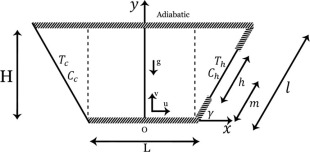
The general schematic configuration is a two-dimensional trapezoid enclosure with two walls of length l inclined at an angle with the x axis, length L which can be assumed to be equal height H of the enclosure for specific angle, as shown in Fig. 1a, along with the coordinates. The sloping walls of the enclosure are specified at two fixed different temperatures and concentrations (. The left wall is at ( and the right wall is partially at ( where ( and (. Also, the remaining right sidewalls, as well as horizontal walls, are assumed to be adiabatic and impermeable to mass transfer.
|
|
|
Figure 1a. Physical configuration. |
Aspect ratio is defined as the ratio of the height H to the length L of the cavity (Ar = H/L). The length of the thermally active part of the right wall is l/2. According to the location of the active thermal zone, three different thermally cases can be visualized as shown in Fig. 1b. In case I, heated zone is located near to the top right wall, in case II it is in the middle and in case III it is located near to the bottom right wall.
|
|
|
Figure 1b. Three different thermally cases. |
2.2. Governing equations and physical boundary conditions
The fluid flow is assumed to be incompressible, Newtonian, and laminar with negligible viscous dissipation. There are no heat generation and chemical reactions, and also surface thermal radiation exchange has not been taken into consideration. Under these descriptions and assumptions, the governing equations for double-diffusive natural convection flow using conservation of mass, momentum, energy and concentration in dimensional form are written as follows:
|
|
(1) |
|
|
(2) |
|
|
(3) |
|
|
(4) |
|
|
(5) |
The mixture density is assumed to be uniform over the enclosure, exception made to the buoyancy term, in which it is taken as a function of both the temperature and concentration levels through the Boussinesq approach
|
|
(6) |
where is the thermal expansion coefficient, and is the concentration expansion coefficient.
The appropriate initial and boundary conditions are
| : | , | For all solid walls, |
| : | , | |
| , | , | |
| , | ||
| , | , | |
| , | ||
| , | ||
| , | ||
| , | ||
| , | and | |
| . | ||
The stream function and vorticity in dimensional form can be defined in the usual way as
|
|
(7) |
Using the following transformation of variables:
|
|
|
|
The governing Eqs. (1), (2), (3), (4) and (5) can be rewritten in the vorticity–stream function formulation as follows:
|
|
(8) |
|
|
(9) |
|
|
(10) |
where
|
|
(11) |
The non-dimensional parameters that appear in the equations are Pr the Prandtl number, the thermal Grashof number, and Le the Lewis number. Parameter is the buoyancy ratio, which is the ratio between the solute and thermal buoyancy forces.
The local Nusselt and Sherwood numbers are defined by ; on the heating section at the right wall and ; on the heating section at the right wall or at the left wall. Here n denotes the normal direction on a plane.
The average Nusselt and Sherwood numbers at the left wall are
|
|
And the average Nusselt and Sherwood numbers on the heating section on the right wall are
|
|
/2 is height of heating section.
The dimensionless form of the initial and boundary conditions is as follows:
| : | , | For all solid walls, |
| : | , | |
| , | , | |
| , | ||
| , | , | |
| , | ||
| , | ||
| , | ||
| , | and | |
| . | ||
3. Solution procedure
After mesh generation of the physical domain, Navier–Stokes equations in trapezoid (physical space) are transformed into a rectangle (computational space) via derivatives, chain rule and then the discretized transport equations are solved in the rectangular computational domain. The governing equations and the stream function equation in conjunction with the initial and boundary conditions have been numerically solved through the Finite Difference Method (FDM). A first-order forward scheme is adopted for time derivation. The stream function field is solved via Point Successive Over Relaxation (PSOR) method, and the Alternating Direction Implicit (ADI) technique is utilized to solve the vorticity, energy, and mass equations. In addition, the convective terms have been discretized using a first-order forward and backward difference via upwind scheme while a second order central differencing is applied to discretize the diffusive terms and the buoyancy for numerical stability. We start from arbitrarily specified initial values of variables, and afterward solve the discretized transient equations by marching in time until an asymptotic steady-state solution is reached. An over-relation parameter of 1.8 is chosen for stream function in order to obtain converged solutions. The convergence of the iteration for stream function solution is obtained at each time step. In order to check for steady-state solution the criterion is employed as follows:
|
|
(12) |
where stands for or S and n is the iteration. The value of is chosen as . The time step used in the computations is varied between 0.0001 and 0.000001 depending on the thermal Grashof number, the angle and mesh size values.
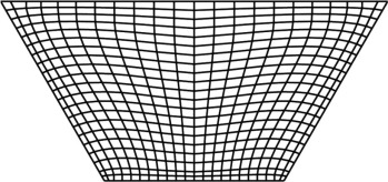
It is worthwhile mentioning that finite-difference equations are solved at discrete points within the domain of interest. Hence, a set of grid points within the domain, as well as the boundaries of the domain, must be specified. Typically, the computational domain is selected to be rectangular in shape where the interior grid points are distributed along the grid lines. The generation of a grid, with uniform spacing, cannot be complex within a rectangular physical domain. However, in some engineering applications the form of the enclosure can also be non-rectangular where imposing a rectangular computational domain on such physical domains is difficult. The reason is owing to the fact that real boundaries are not coincided with the mathematical space. Asan and Namli [48] and Haese and Teubner [49] used a regular rectangular grid placed over the triangular cavity as the diagonal elements coincided with points on the slopping surface. Later, Varol et al. [50] and Saleh et al. [51] also followed the technique presented by Haese and Teubner [49]. They solved the equations on inclined walls in the trapezoidal enclosure by approximating the inclined boundaries with staircase-like zigzag lines. They had to select a suitable inclination angle and aspect ratio in order to maintain the inclined walls match exactly at the nodal point. Otherwise, the implementation of the boundary conditions on inclined walls required some kind of interpolation which might lead to a substantial reduction in accuracy at the place of greatest sensitivity such as corners. To overcome the problem, the physical space is transferred to a computational space, Fig. 2a. A generalized coordinate system is introduced for accomplishing this transformation. In fact, the nonrectangular grid system in the physical space is mapped to a rectangular uniform grid spacing in the computational domain by taking advantage of such coordinate system. The main issue is identifying the location of the grid points in the physical domain. In the work of Basak et al. [52] the computational grid in the trapezoidal domain was generated through mapping the trapezoidal domain into a square domain. They used some base functions for mapping the trapezoidal space into the square space. It can be said that the method appeared to be very fast, from a computational point of view, and the grid generation via the algebraic method was not difficult. It also provided a reasonable grid system with continuous and smooth metric distributions. However, the control of grid smoothness and skewness did not seem to be very simple in this technique. Also, discontinuities at a boundary may propagate into the interior region that could lead to errors due to sudden changes in the metrics. As a result, implementation of boundary conditions required some special tricks. For example, Basak et al. [52] utilized basis functions for performing boundary conditions and calculating the Nusselt numbers. To handle discussed difficulties, grid systems have been generated by a partial differential equation technique in the current study. In this method, a system of PDEs is solved to obtain the grid points in the physical domain, but the computational space is a rectangular shape with uniform grid spacing. As seen from Fig. 2b, the grid lines are perpendicular to all surfaces that improve the accuracy and simply the implementation of the boundary conditions and calculation of the Nusselt and Sherwood numbers at the surfaces, especially at the inclined walls. In consequence, it is significant to note that the PDE method has a high ability to generate grid system in any complex shapes as it enables the flow to be calculated precisely.
|
|
|
Figure 2a. Mapping of physical trapezoidal space in coordinate system to a square computational space in coordinate system. |
|
|
|
Figure 2b. Mesh of the enclosure generated in this work. |
4. Grid sensitivity study and code validation
4.1. Grid independent check
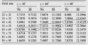
To decide the suitable grid size for the trapezoidal enclosure studied in this paper, numerical solutions are done for different grid sizes from 21 × 21 to 91 × 91 for three different inclination angles and . Table 1 indicates optimal grid sizes for three different inclination angles . As it is seen from the table a further refinement of grids from 41 × 41, 51 × 51 and 61 × 61 for , , and respectively, to 91 × 91 does not exert a significant effect on the results in terms of the average Nusselt and Sherwood numbers. As a consequence, a uniform grid of 61 × 61 points is sufficiently proper to ensure a grid independent solution for all of the angles in this work.
4.2. Validation
Prior to discussion on obtaining results, it is necessary to verify the present computation procedure. However, owing to lack of relevant appropriate findings in the existing literature describing the enclosure configuration and boundary conditions considered in this work the current results have been validated against those for the square enclosures. As the first test, the results are compared with those presented by Nikbakhti and Rahimi [41] which refer to a square cavity having partially thermally active walls. The comparison is shown in Table 2. In the following, as an additional verification, the computer code is validated with Kuznetsov and Sheremet [53] for double-diffusive natural convection in a two-dimensional square enclosure and the comparison is provided in Table 3.
| Le | Model | Case I | Case II | Case III | |||
|---|---|---|---|---|---|---|---|
| 2.0 | Ref. [41] | 5.4705 | 8.1249 | 6.6783 | 10.3542 | 7.6090 | 10.4376 |
| Present | 5.8030 | 8.6535 | 7.1708 | 10.3649 | 7.8143 | 10.4611 | |
| 3.0 | Ref. [41] | 5.5125 | 10.0799 | 6.7335 | 11.6213 | 7.6558 | 12.2213 |
| Present | 5.9687 | 10.4702 | 7.2851 | 12.1955 | 7.9005 | 12.4760 | |
| Gr | Ref. [53] | Present | ||
|---|---|---|---|---|
| 103 | 2.18 | 5.29 | 2.21 | 5.33 |
| 3.65 | 8.94 | 3.80 | 9.31 | |
| 104 | 4.53 | 11.29 | 4.68 | 11.29 |
It can be observed that the obtained results of the present study indicate good agreement with those from the earlier investigations and therefore, they provide confidence to the accuracy of the current numerical code.
5. Results and discussion
A numerical analysis has been carried out on double diffusive natural convection heat and mass transfer in a partially heated trapezoidal enclosure. Three different cases can be considered based on the arrangement of the partially heating active part on the right inclined wall. Influences of several parameters, which describe the flow behavior and heat and mass transfer characteristics in the enclosure, including location of heating part, angle of inclined wall, thermal Grashof number, Prandtl number, and Lewis number have been discussed. To indicate the fluid flow and heat and mass transfer phenomenon inside the trapezoidal enclosure, the results are demonstrated in the form of isotherms, isoconcentrations, streamlines, mid-height velocity and mid-weight velocity profiles.
5.1. Time–space variations
In the first subsection, the time development of fluid motion, temperature, and concentration distribution across the trapezoidal enclosure is analyzed. According to the initial condition at , the fluid contained in the enclosure is at and and consequently does not produce heat and mass inside the cavity. It is worth recalling that for , the temperature of the right partially active sidewall is changed to and that of the left sidewall remains at . While the left wall is still maintained at low concentration, the right partially heated active wall has higher concentration, . Because the right side wall is partially imposed to a higher temperature than that of the fluid, the fluid particles near the heated active sidewall become hot and their temperature increases. In the initial stage, while the buoyancy forces are too weak the fluid particles accelerate due to conduction and, therefore, spread across the enclosure. In fact, a small change in the fluid spreads instantly throughout the fluid. This is due to the incompressible assumption, the continuity equation and the motion of the fluid in the area enclosed. Thus, it is observed that the contour of streamlines spreads across the cavity despite the smallness of the velocities values in the initial stage.
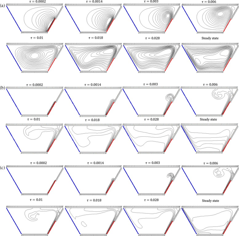
Fig. 3(a)–(c) illustrates streamlines, isotherms and isoconcentrations in the transient-state regime for and in case III.
|
|
|
Figure 3. Time–space variations of (a) streamlines, (b) isotherms and (c) isoconcentrations for case III with , , and . |
Streamlines show that at the beginning, the fluid contained within the enclosure is activated by the heating active zone and a weak counterclockwise rotating cell appears near the right heated wall. As time passes the strength of the cell increases, and the cell expands and moves slowly toward the center so that the center of the circulation is placed in the central zone of the enclosure when = 0.01. As we further advance in time the rotation center is shifted to the top-right, and the cell grows in its size and spreads throughout the enclosure. Eventually, in the steady state the fluid field intensifies due to the domination of the convection and occupies the whole enclosure.
At the initial time steps, isothermal and isoconcentration lines are restricted to a thin region adjacent to the partially heated active right wall in an almost parallel manner showing the conduction mode of heat transfer dominated in the enclosure. As time goes on, the convection is started, and the isotherms and isoconcentrations are gradually spreading throughout the enclosure. With further increasing time, the temperature and concentration lines reach the left sidewall and the convection becomes dominant across the enclosure. It is useful to note that the isoconcentration lines are more distorted and indicate the sharper gradients at the thermally active zones implying higher mass transfer inside the enclosure.
5.2. Effect of heating locations
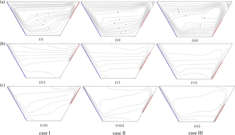
Fig. 4(i)–(ix) demonstrates the flow pattern, the temperature and concentration distributions for three different heating locations by plotting the contours of stream lines, isotherms and isoconcentrations with following characteristics: and .
|
|
|
Figure 4. (a) Streamlines, (b) isotherms and (c) isoconcentrations for case I (left), case II (middle), and case III (right) with , , and . |
Fig. 4(i)–(iii) shows the flow patterns inside the enclosure for three different cases. It is observed that the flow is impelled upward by the active heated right sidewall and then downward by the cold left inclined wall. This leads to the appearance of the principal cell in the counterclockwise rotation direction that occupies the whole enclosure seen in all cases considered. In the first case, when the heating zone is placed on the top of the right sidewall (Fig. 4(i)), most of the fluid moves around the top part of the enclosure and the circulation is stronger due to the existence of a partially heated wall and the remaining parts are less activated due to the adiabatic walls. In this case, the flow is too weak with . It is seen that when the heating zone moves to the middle of the right sidewall, the strength of the flow is intensified, Fig. 4(ii). In the last case, where the heating zone is located on the bottom, the flow gets enough free space paths for circulation before meeting top adiabatic boundary and therefore, it accelerates and occupies the whole enclosure. The flow is further grown in strength and the velocity, and circulation rate is higher compared with other cases with .
Fig. 4(iv)–(vi) illustrates the temperature distribution inside the enclosure for three mentioned cases by plotting the contours of isotherms. In Fig. 4(iv) the corresponding isotherms indicate relatively parallel temperature distribution near the heating active zone in the top part of the enclosure with the domination of conduction mode of heat transfer. When the heating section moves to the bottom part of the sidewall a thermal boundary layer is formed close to the active zone, and the convection can be seen from isotherms, Fig. 4(vi). In this case, the heat transfer rate performance has been considerably enhanced in the cavity. Generally, crowded boundary layers are observed on the cooled inclined left sidewall in all three cases and as an interesting result this boundary layer is just formed on the right sidewall when the heating active section is located partially on the bottom of the right sidewall.
The isopleths of concentration, Fig. 4(vii)–(ix), have similar manner as that of temperature, which is mainly due to the similarity of energy and mass transfer equations. However, isoconcentration lines are more distorted and indicate the sharper gradients at the thermally active zones implying higher mass transfer in the cavity. It is also observed that the formed thermal boundary layer compared to the formed solutal boundary layer is thicker. It is worthy to note that the impact of the thermal diffusivity is greater than that of the mass diffusivity on fluid flow since the Schmidt number is over the Prandtl number (Le = 3).
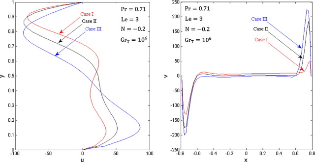
In order to gain a deeper insight into the fluid flow behavior for cases I, II and III, the flow velocities along the mid-part of the trapezoidal cavity are exhibited in Fig. 5. It is seen that the horizontal velocity profiles close to the top wall has an almost equal magnitude in three cases. On the other hand, the profiles reveal that the horizontal component of velocity close to the bottom boundary is affected significantly by changing the location of the heated zone on the right sidewall. As the bottom part of the right wall is heated, the fluid near the thermal active zone has enough space to accelerate vertically before meeting the top adiabatic wall, so it manages to obtain higher velocity. However, when the middle or top part of the right wall is heated, the velocity of the fluid adjacent to the bottom boundary has lower magnitude. Thus, the horizontal velocity close to the bottom wall is maximum for case III. It is also observed that case III has the highest value of vertical velocity while the lowest vertical velocity is obtained in case I.
|
|
|
Figure 5. Velocity profiles for three different thermal cases. |
5.3. Effects of thermal Grashof number
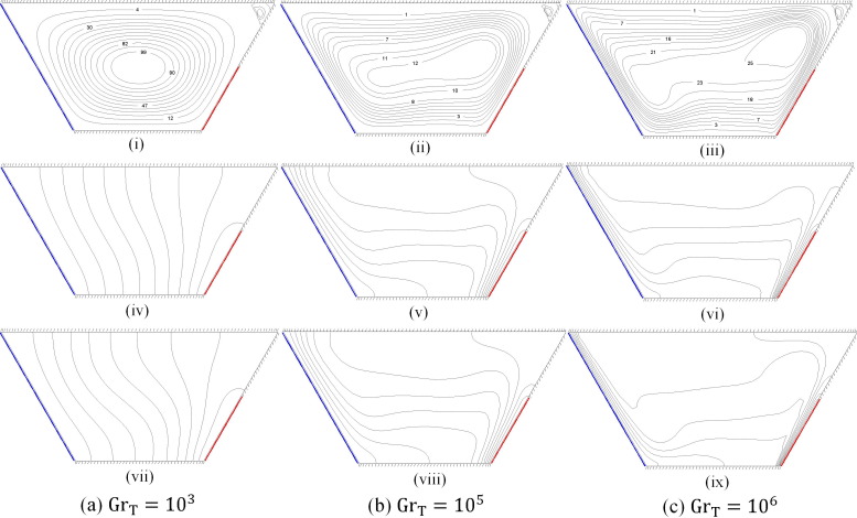
The effects of the thermal Grashof number on the flow field, temperature and concentration distributions have been studied in this subsection. Fig. 6(i)–(ix) shows the contours of streamlines, isotherms and isoconcentrations in Case III for and three different values of the thermal Grashof numbers including , and .
|
|
|
Figure 6. Streamlines (up), isotherms (middle) and isoconcentrations (down) for case III and (a) (b) (c) with , , . |
For low Grashof numbers such as , a single cell rotating around the center of the enclosure in the counterclockwise direction is seen and its strength is too weak (Fig. 6(i)). In low values of Gr conduction mode of heat transfer becomes dominant in the enclosure owing to the stationary of the fluid flow and the maximum value of the stream function is only . With increasing of Gr , the flow becomes intensified, and the convection mode of heat transfer appears in the enclosure. Further increasing of the thermal Grashof number leads to the increase in the size of the principal cell and the fluid flow almost occupies the whole cavity. For higher values of the thermal Grashof number, i.e. , the circulation rate increases considerably due to the domination of convection mode in the enclosure. The center of rotation is shifted toward the top-right portion with one inner cell appearing in the main cell as shown in Fig. 6(iii).
For low thermal Grashof numbers such as , the corresponding isotherms and isoconcentrations indicate almost parallel temperature and concentration distributions in the enclosure respectively, although the isoconcentrations are more distorted, Fig. 6(iv) and (vii). Such distributions reveal that the dominant mode of heat transfer within the enclosure is conduction. As the thermal Grashof number increases the convection mode of transfer is commenced, and the distortion of the isotherm and isoconcentration becomes gradually greater. Isotherms and isoconcentrations move toward the active thermal sidewalls, and it leads to the formation of a thermal and solutal boundary, respectively layer along the active zone. Furthermore, the thickness of the thermal and solutal boundary layers reduces with increasing the thermal Grashof number, as seen from Fig. 6(vi) and (ix). It is interesting to note that isoconcentration lines demonstrate the sharper gradients compared to the isothermal lines in the enclosure indicating the higher mass transfer.
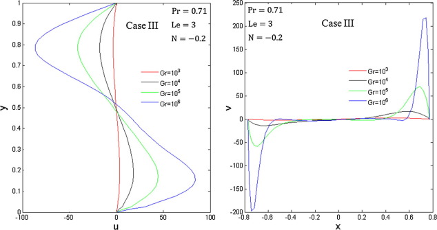
In order to have a better understanding of the influence of the thermal Grashof number on the flow velocities, the mid-height and mid-width velocities are demonstrated in Fig. 7. It is obvious that increasing the thermal Grashof number leads to increase in the velocity. For low values of thermal Grashof numbers, i.e. , the fluid flow is too weak, and the dominant mode of heat transfer in the enclosure is conduction. However, with further increase in the Gr the convection appears so that for a high value of thermal Grashof number, i.e. , convection becomes the dominant mode of heat transfer in the enclosure. Consequently, it leads to the considerable rise in the flow velocity. It is further observed a symmetric trend of the vertical and horizontal velocity profiles that show the direction of the flow within the enclosure.
|
|
|
Figure 7. Velocity profiles for different thermal Grashof numbers. |
5.4. Effects of inclination angles
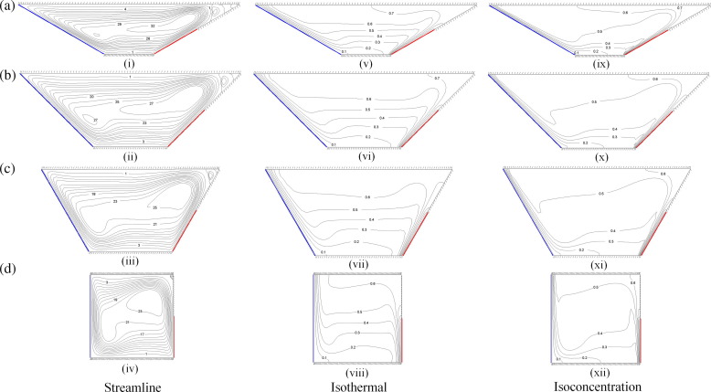
In this part of the study, the effects of sidewall inclination angle on the flow field, temperature and concentration distributions are analyzed. The flow patterns, isotherms and isoconcentrations for Case III with and are displayed in Fig. 8(i)–(xii).
|
|
|
Figure 8. Streamlines (on the left), isotherms (in the middle), and isoconcentrations (on the right) for (a) γ = 30°, (b) γ = 45°, (c) γ = 60°, and (d) γ = 90° in case III with , , , and . |
Fig. 8(i)–(iv) indicates the effect of inclination angle variations on the flow pattern. As it can be seen from these figures, a principal cell occupies the whole enclosure for all inclination angles with one inner cell whose size becomes smaller as the inclination angle increases. It is further observed that the flow separates from the walls for low values of inclination angle like so that one detachment zone is seen at the top-right corner. Interestingly, as the inclination angle increases this phenomenon gradually disappears because of the insignificant dissimilarity for high angles.
For small values of the inclination angle, , isotherms exhibit wavy variation in the enclosure as seen from Fig. 8(v). However with further increasing of angle, isotherms demonstrate regular distribution between the heated zone and the cold sidewall and they are parallel to each other. For , distribution of isotherms demonstrates relatively sinusoidal-shaped variation in the middle of the square cavity as shown in Fig. 8(viii).
As it is illustrated in Fig. 8(ix)–(xii), the isoconcentration has similar behavior as isothermal due to the similarity of energy and mass transfer equations. But, according to the Lewis number Le = 3, the thermal diffusivity has a greater effect than the mass diffusivity on fluid. As a result, formed solutal boundary layer in relation to the formed thermal boundary layer is thinner. In addition, isoconcentrations also show much more wavy variation for all angles compared with isotherms implying higher mass transfer in the enclosure.
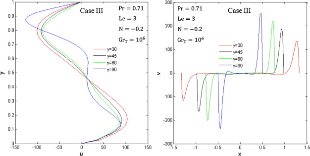
Fig. 9 displays the horizontal and vertical velocity profiles at the mid-vertical and horizontal planes of the enclosure for different inclination angles. It is observed from the horizontal velocity profiles that the velocities have symmetric manner for but for the value of velocity is lower at the bottom half of the enclosure than that of the upper half. In addition, the value of the horizontal velocity is affected minimally by the increase in inclination angle for while it is affected significantly for . On the contrary, the vertical velocity profiles show that the fluid particles near the heated part of the right wall become hot and, therefore, rise along the sidewall whereas the fluid particles fall along the cold left sidewall. Interestingly, it tends to decrease with the reduction in due to increasing the horizontal distance. In other words, the fluid particle moves vertically with higher velocity as the inclination angle increases.
|
|
|
Figure 9. Velocity profiles for four different inclination angles. |
5.5. Heat and mass transfer rates: average Nusselt and Sherwood numbers
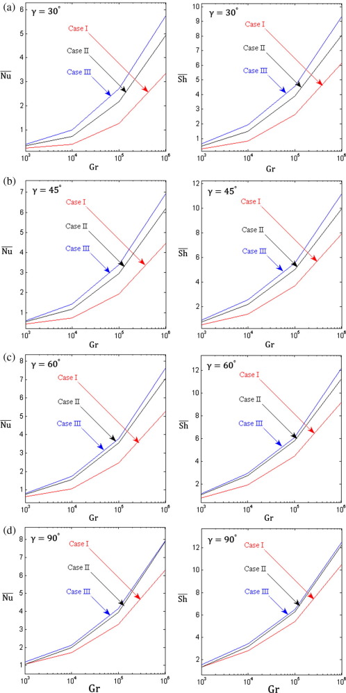
The heat and mass transfer rate is measured using the average Nusselt and Sherwood numbers. Firstly, to appraise how the different locations of the heated zone of the right sidewall influence the heat and mass transfer performance, the average Nusselt and Sherwood numbers are plotted as a function of Grashof number for three different mentioned cases when , 45°, 60° and 90° as shown in Fig. 10(a)–(d). Overall, the average Nusselt and Sherwood numbers increase as the Grashof Number increases. As a consequence, heat and mass transfer are ascending functions of Grashof number. It is also interesting to observe that the rate of heat and mass transfer (based on the average Nusselt and Sherwood numbers) depends on the position of the partial active heated wall. Thus, case III is the most effective case in terms of the performance of heat and mass transfer in the enclosure for all inclination angles. It is also observed that the variation of the location varies of the heated zone does not exert a considerable effect on the average Nusselt and Sherwood numbers for low values of thermal Grashof number. Thus, there is a minimal difference among three cases based on the rate of heat and mass transfer. However, the effect of partial active heated portion becomes much more significant for higher values of Gr. This is due to the convection domination at high Grashof numbers in the enclosure. As it can be seen from Fig. 10(a)–(d), the values of and tend to increase with increasing of wall inclination angle as the maximum values of and are obtained for a square cavity.
|
|
|
Figure 10. Variation of the average Nusselt number (on the left) and the average Sherwood number (on the right) with the thermal Grashof number for different cases: (a) , (b) , (c) , and (d) at , |
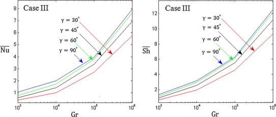
A detailed description is demonstrated in Fig. 11 to present the effects of the variation of the sidewall inclination angle on the heat and mass transfer performance. The average Nusselt and Sherwood numbers illustrate that the heat and mass transfer rate increases with the increase in the inclination angle of the sidewall. This is mainly because the distance between the cold wall and partially heated wall decreases, and therefore less thermal resistance happens in the enclosure. As a result, the maximum rate of heat and mass transfer occurs in the square enclosure while the rate is minimum in a trapezoidal enclosure with inclination angle owing to the long distance between the cold and partially heated sidewalls.
|
|
|
Figure 11. Variation of the average Nusselt number (on the left) and the average Sherwood number (on the right) with the thermal Grashof number for different inclination angles in case III at , |
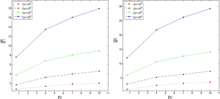
The influence of Prandtl number on heat and mass transfer phenomenon for different Grashof numbers is exhibited in Fig. 12 in Case III for and . The figure shows that the effect of the Prandtl number on the average Nusselt and Sherwood numbers is relatively insignificant at low values of thermal Grashof number. However, the Prandtl number has a significant influence on heat and mass transfer performance at high values of thermal Grashof number so that the average Nusselt and Sherwood numbers are found to increase substantially as Prandtl number increases.
|
|
|
Figure 12. Variation of the average Nusselt number (on the left) and the average Sherwood number (on the right) with the Prandtl number for different thermal Grashof numbers in case III at |
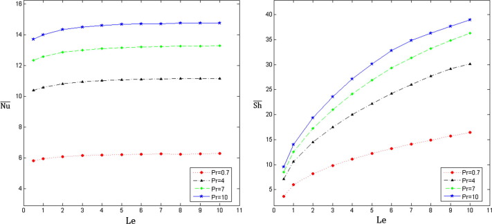
Finally, Fig. 13 illustrates the variation of the average Nusselt and Sherwood numbers with the Lewis number for four values of (air), (R-12 refrigerant), (salt water) and (fruit juice) when and . It is seen that the Lewis number has a different impact on and . The figure demonstrates that the average Nusselt number is relatively independent of Le which means that the heat transfer maintains constant with increasing of Lewis number.
|
|
|
Figure 13. Variation of the average Nusselt number (on the left) and the average Sherwood number (on the right) with the Lewis number for different Prandtl numbers in case III at . |
On the contrary, the average Sherwood number experiences a considerable rise with the increase of Lewis number. Therefore, it can be concluded that the transmission of energy is not enhanced with increasing of Lewis number while it leads to improving the mass transfer performance inside the enclosure. It is also seen that the average Nusselt and Sherwood numbers increase as the Prandtl number increases and therefore, it leads to the heat and mass transfer enhancement in the enclosure.
6. Conclusion
The present study is involved with the numerical simulation of heat and mass transfer by natural convection in a two-dimensional trapezoidal enclosure partially heated from the right sidewall. The left sidewall is maintained cold while the horizontal walls, as well as inactive part of the right sidewall, are assumed to be adiabatic and impermeable to mass transfer. The computations are performed for three different cases when the thermal active part is located on the top (case I), in the middle (case II), and on the bottom (case III) of the right sidewall. Finite difference method has been adopted for the solution of the problem, and the mesh generation of the physical domain is done via the elliptic grid generator technique. This investigation is conducted for various parameters and the significant results obtained can be summarized as follows. It is found that the position of the heated zone exerts a substantial influence on the fluid flow and the heat and mass transfer rate so that the heat and mass transfer performance of the enclosure is obtained to be higher in case III than case II and case I. The inclination angle of the slopping walls also has an effect on the values of and so that the performance of the heat and mass transfer inside the enclosure is enhanced with increasing of . Furthermore, the average Nusselt and Sherwood numbers increase as the thermal Grashof number increases that leads to increasing the heat and mass transfer rate in the cavity. In particular, the transport of heat and mass rises considerably for . Increasing the Prandtl number has no considerable influence on the average Nusselt and Sherwood numbers for whereas there is a significant rise in the rate of heat and mass transfer as Prandtl number increases for higher values of thermal Grashof number. While increasing the Lewis number causes improving the mass transfer performance, it has no significant effect on the energy transfer inside the enclosure.
References
- [1] J.S. Turner; Double diffusive phenomena; Annu. Rev. Fluid Mech., 6 (1974), pp. 37–56
- [2] R.W. Schmitt; Double diffusion in oceanography; Annu. Rev. Fluid Mech., 26 (1994), pp. 255–285
- [3] H.E. Huppert, R.S.J. Sparks; Double-diffusive convection due to crystallization in magmas; Annu. Rev. Earth Planet. Sci., 12 (1984), pp. 11–37
- [4] S. Ostrach; Natural convection with combined driving forces; Physicochem. Hydrodyn., 1 (1980), pp. 233–247
- [5] R. Viskanta, T.L. Bergman, F.P. Incropera; Double diffusive natural convection; S. Kakac, W. Aung, R. Viskanta (Eds.), Natural Convection: Fundamentals and Applications, Hemisphere, Washington, DC (1985), pp. 1075–1099
- [6] A. Bejan; Mass and heat transfer by natural convection in a vertical cavity; Int. J. Heat Fluid Flow, 6 (1985), pp. 149–159
- [7] D.A. Nield, A. Bejan; Convection in Porous Media; Springer-Verlag (1992)
- [8] J.S. Turner; The coupled turbulent transport of salt and heat across a sharp density interface; Int. J. Heat Mass Transfer, 8 (1965), pp. 759–761
- [9] H. Fernando; Buoyancy transfer across a diffusive interface; J. Fluid Mech., 209 (1989), pp. l–34
- [10] B. Gebhart, L. Pera; The nature of vertical natural convection flows resulting from the combined buoyancy effects of thermal and stress diffusion; Int. J. Heat Mass Transfer, 14 (1971), pp. 2025–2050
- [11] H. Sun, G. Lauriat, D.L. Sun, W.Q. Tao; Transient double-diffusive convection in an enclosure with large density variations; Int. J. Heat Mass Transfer, 53 (2010), pp. 615–625
- [12] K.N. Morshed, M.R. Sharif, A.W. Islam; Laminar mixed convection in a lid-driven square cavity with two isothermally heated square internal blockages; Chem. Eng. Commun., 202 (2015), pp. 1176–1190
- [13] M. Mobedi, U. Ozkol, B. Sunden; Visualization of diffusion and convection heat transport in a square cavity with natural convection; Int. J. Heat Mass Transfer, 53 (2010), pp. 99–109
- [14] M. Corcione, S. Grignaffini, A. Quintino; Correlations for the double-diffusive natural convection in square enclosures induced by opposite temperature and concentration gradients; Int. J. Heat Mass Transfer, 81 (2015), pp. 811–819
- [15] T.R. Mahapatra, D. Pal, S. Mondal; Effects of buoyancy ratio on double-diffusive natural convection in a lid-driven cavity; Int. J. Heat Mass Transfer, 57 (2013), pp. 771–785
- [16] M.A. Teamah; Numerical simulation of double diffusive natural convection in rectangular enclosure in the presences of magnetic field and heat source; Int. J. Therm. Sci., 47 (2008), pp. 237–248
- [17] M.A. Teamah, A.F. Elsafty, E.Z. Massoud; Numerical simulation of double-diffusive natural convective flow in an inclined rectangular enclosure in the presence of magnetic field and heat source; Int. J. Therm. Sci., 52 (2012), pp. 161–175
- [18] F. Moukalled, S. Acharya; Natural convection in trapezoidal cavities with baffles mounted on the upper inclined surfaces; Numer. Heat Transfer, Part A, 37 (6) (2000), pp. 545–565
- [19] T. Boulard, C. Kittas, J.C. Roy, S. Wang; Convective and ventilation transfers in greenhouses, Part 2: determination of the distributed greenhouse climate; Biosyst. Eng., 83 (2) (2002), pp. 129–147
- [20] P.H. Oosthuizen; Free convective flow in an enclosure with a cooled inclined upper surface; Comput. Mech., 14 (5) (1994), pp. 420–430
- [21] L. Iyican, Y. Bayazitoglu, L.C. Witte; An analytical study of natural convective heat transfer within trapezoidal enclosure; J. Heat Transfer, 102 (8) (1980), pp. 640–647
- [22] L. Iyican, L.C. Witte, Y. Bayazitoglu; An experimental study of natural convection in trapezoidal enclosures; J. Heat Transfer, 102 (8) (1980), pp. 648–653
- [23] S.W. Lam, R. Gani, J.G. Symons; Experimental and numerical studies of natural convection in trapezoidal cavities; ASME J. Heat Transfer, 111 (1989), pp. 372–377
- [24] M. Pericacute; Natural convection in trapezoidal cavities; Numer. Heat Transfer A, 24 (1993), pp. 213–219
- [25] F. Moukalled, M. Darwish; Natural convection in a partitioned trapezoidal cavity heated from the side; Numer. Heat Transfer Part A, 43 (2003), pp. 543–563
- [26] R.A. Kuyper, C.J. Hoogendoorn; Laminar natural convection flow in trapezoidal enclosures; Numer. Heat Transfer, Part A, 28 (1) (1995), pp. 55–67
- [27] Z.F. Dong, M.A. Ebadian; Investigation of double-diffusive natural convection in a trapezoidal enclosure; J. Heat Transfer – Trans. ASME, 116 (1994), pp. 492–495
- [28] M. Boussaid, A. Djerrada, M. Bouhadef; Thermosolutal transfer within trapezoidal cavity; Numer. Heat Transfer, Part A, 43 (4) (2003), pp. 431–448
- [29] J.T. Van der Eyden, T.H. Van der Meer, K. Hanjalic, E. Biezen, J. Bruining; Double-diffusive natural convection in trapezoidal enclosures; Int. J. Heat Mass Transfer, 41 (13) (1998), pp. 1885–1898
- [30] E. Papanicolaou, V. Belessiotis; Double-diffusive natural convection in an asymmetric trapezoidal enclosure: unsteady behavior in the laminar and the turbulent-flow regime; Int. J. Heat Mass Transfer, 48 (2005), pp. 191–209
- [31] D. Kuhn, P.H. Oosthuizen; Unsteady natural convection in a partially heated rectangular cavity; J. Heat Transfer, 109 (1987), pp. 789–801
- [32] A. Valencia, R.L. Frederick; Heat transfer in square cavities with partially active vertical walls; Int. J. Heat Mass Transfer, 32 (1989), pp. 1567–1574
- [33] N. Yucel, H. Turkoglu; Natural convection in rectangular enclosures with partial heating and cooling; Heat Mass Transfer, 29 (1994), pp. 471–477
- [34] M.M. El-Refaee, M.M. Elsayed, N.M. Al-Najem, A.A. Noor; Natural convection in partially cooled tilted cavities; Int. J. Numer. Methods Fluids, 28 (1998), pp. 477–499
- [35] T.H. Chen, L. Chen; Study of buoyancy-induced flows subjected to partially heated sources on the left and bottom walls in a square enclosure; Int. J. Therm. Sci., 46 (2007), pp. 1219–1231
- [36] S.A. Nada, M. Moawed; Free convection in tilted rectangular enclosures heated at the bottom wall and vented by different slots-venting arrangements; Exp. Therm. Fluid Sci., 28 (2004), pp. 853–862
- [37] S.A. Nada; Natural convection heat transfer in horizontal and vertical closed narrow enclosures with heated rectangular finned base plate; Int. J. Heat Mass Transfer, 50 (2007), pp. 667–679
- [38] S.A. Nada; Experimental investigation of natural convection heat transfer in horizontal and inclined annular fluid layers; Heat Mass Transfer, 44 (2008), pp. 929–936
- [39] Y. Varol, H.F. Oztop, I. Pop; Natural convection in right angle porous trapezoidal enclosure partially cooled from inclined wall; Int. J. Heat Mass Transfer, 36 (2009), pp. 6–15
- [40] M.A. Teamah, M.M. Khairat Dawood, W.M. El Maghlany; Double diffusive natural convection in a square cavity with segmental heat sources; Eur. J. Sci. Res., 54 (2011), pp. 287–301
- [41] R. Nikbakhti, A.B. Rahimi; Double-diffusive natural convection in a rectangular cavity with partially thermally active side walls; J. Taiwan Inst. Chem. Eng., 43 (2012), pp. 535–541
- [42] R. Nikbakhti, J. Khodakhah, Numerical investigation of double diffusive buoyancy forces induced natural convection in a cavity partially heated and cooled from sidewalls, Engineering Science and Technology, an International Journal, Article in Press, Corrected Proof, 2015.
- [43] R. Nikbakhti, A. Saberi; Natural convection heat and mass transfer in a rectangular porous cavity having partially thermally active walls; Int. J. Mech. Eng. Robot. Res., 5 (2016), pp. 72–76
- [44] N. Nithyadevi, R. Yang; Double diffusive natural convection in a partially heated enclosure with Soret and Dufour effects; Int. J. Heat Fluid Flow, 30 (2009), pp. 902–910
- [45] F. Oueslati, B. Ben-Beya, T. Lili; Double-diffusive natural convection and entropy generation in an enclosure of aspect ratio 4 with partial vertical heating and salting sources; Alexandria Eng. J., 52 (2013), pp. 605–625
- [46] S.K. Jena, S.K. Mahapatra, A. Sarkar; Double diffusive buoyancy opposed natural convection in a porous cavity having partially active vertical walls; Int. J. Heat Mass Transfer, 62 (2013), pp. 805–817
- [47] S. Chen, J. Tölke, M. Krafczyk; Numerical investigation of double-diffusive (natural) convection in vertical annuluses with opposing temperature and concentration gradients; Int. J. Heat Fluid Flow, 31 (2010), pp. 217–226
- [48] H. Asan, L. Namli; Numerical simulation of buoyant flow in a roof of triangular cross-section under winter day boundary conditions; Energy Build., 33 (2001), pp. 753–757
- [49] P.M. Haese, M.D. Teubner; Heat exchange in an attic space; Int. J. Heat Mass Transfer, 45 (2002), pp. 4925–4936
- [50] Y. Varol, H.F. Oztop, I. Pop; Maximum density effects on buoyancy-driven convection in a porous trapezoidal cavity; Int. Commun. Heat Mass Transfer, 37 (2010), pp. 401–409
- [51] H. Saleh, R. Roslan, I. Hashim; Natural convection in a porous trapezoidal enclosure with an inclined magnetic field; Comput. Fluids, 47 (2011), pp. 155–164
- [52] T. Basak, S. Roy, S.K. Singh, I. Pop; Finite element simulation of natural convection within porous trapezoidal enclosures for various inclination angles: effect of various wall heating; Int. J. Heat Mass Transfer, 52 (2009), pp. 4135–4150
- [53] G.V. Kuznetsov, M.A. Sheremet; A numerical simulation of double-diffusive conjugate natural convection in an enclosure; Int. J. Therm. Sci., 50 (2011), pp. 1878–1886
Document information
Published on 12/04/17
Licence: Other
Share this document
Keywords
claim authorship
Are you one of the authors of this document?
