Presented at
ISEF 2005 - XII International Symposium on Electromagnetic Fields
in Mechatronics, Electrical and Electronic Engineering
Baiona, Spain, September 15-17, 2005
Abstract
Computational electromagnetism requires a wide range of numerical methods depending on the application, the topology of the geometry, the frequency and the quality of the solution. Different efforts have been done to develop a universal software package able to deal with any problem, by integrating existing specific modules in the same interface. Nevertheless, modern computational approaches suggest to use a common basic environment, as high level computing lenguage, to be adapted to the requirements done by the end-user. Following this philosophy, this paper proposes three useful computer tools, combining the most usual requirements, to be customised for any electromagnetic problem.
Brief State of the Art
Different classifications of the electromagnetic problems can be done, but considering the growing and diverse community of developers and users, we will follow a scheme based on the applications or, in other words, the user initial requirements:
A first level or requirements is done by the purpose of the results: academic, industrial or research.
The first is basically focused on teaching electromagnetic concepts, showing some materials properties (magnets, superconductors, dielectrics) or explain the differences between basic configurations (a dipole, the mirror effect, boundary conditions, etc). It does not require high precision results, and the complex models should be avoided. Nevertheless, it is important to allow the easy modification of the parameters (geometry, materials, load and boundary conditions) by the students. In this case, the precision of the results should be limited to reduce the computing time.
The second case, industrial applications, typically demands a very precise results. The possibility of modify the parameters of the problem is not so important as the quality of obtained solution. The industrial products or processes use to have well defined materials, components and limited device configurations, and the technological innovations basically depend on minor changes. Usually, the computing time is not so important as the details of the results. However, for some industrial designs is only needed a qualitative comparison of solutions between two possible designs. For example, to design magnetic screens for TV receptors is needed to consider the non linearity of the materials as well as the low thickness of the screen, with a high computing cost. It seems to be more convenient to include an optimisation algorithm using just lineal materials, and deciding the best design by comparing qualitative solutions.
Finally, the research world moves from one scenario (the industrial) to the other (the academic), trying to provide new developments, new answers to the questions coming from the industry, by obtaining a new level of the abstraction of the problem, but exploring the basic concepts, the open possibilities to better solve those questions.
Applications
By Industry, there are two traditional fields in computational electromagnetism: related to communication systems, usually equivalent to full wave problems, and related to industrial machines, usually working with quasistatic (or uncoupled) fields. Nevertheless, the electronic topics belong to both disciplines, make more difficult this basic classification.
Electrical machines is one of the first electromagnetic topics [1] where the numerical methods was applied, probably due to their similar formulation to the thermal or structural problems, based in the Poisson equation. This field includes computation of the magnetic fields in motors, transformers and any other device including non linear magnetic materials (permanent magnets, ferromagnetic composes, etc…) The static approach should be enough for many of the problems, and the quasistatic solution, usually in the time domain, includes the estimation of the Eddy currents, but without considering the whole coupling between the electric and magnetic field. This kind of modules are also able to design magnetic screenings, magnetic sensors or complex systems for scientific devices, such as the magnets for Synchrotrons. It can be used also for low frequency electronic circuits, but mainly coupled to thermal modules to compute the heat dissipation, for example. At higher frequencies, where the circuit dimensions are greater that the wavelength, it is required full wave electromagnetic modules (transmission lines, radiofrequency and microwave circuits and devices, etc).
Typical telecommunication problems, quite close to the industrial machines, are those requiring the computation of the electromagnetic compatibility, to obtain the emission created by high frequency (in terms of the dimension of the system) sources, to avoid interferences between electronic devices and circuits. Analogous simulation modules are used to improve the design of mobile communications systems (cell phones, radio antennas, bluetooth technology, etc), to compute the electromagnetic radiation absorbed by the human body (the SAR, Specific Absortion Rate).
But the highest computing cost electromagnetic problems are those with open domains and big dimensions in term of wavelength, where the full wave model is also used. It is the case of most of the antenna related problems (antenna design, radiation diagram computation, antenna radiation effects on the environment, placement of antennas in aerostructures, wideband and multi-frequency antennas, smart antennas and arrays). It is equivalent to the RCS (Radar Cross Section) computation, to predict the shape of objects, improve radar detection systems by exploring the propagation effects on communications and radar systems (e.g. atmosphere, complex terrains), etc.
Last but not less, new emerging technologies are requiring the combination of disciplines at high level, now possible thanks to the individual advances of each of them, but an exiting challenge putting all together. Two good examples are the food technologies, where the thermal, fluid dynamic and electromagnetism are the basic phenomena to better understand and improve the sterilisation, drying and other complex processes. The second is the bio-engineering, assuming the human body as a complex mechanical, thermal, fluid and electromagnetic system, with promising results to advance in the medical sciences.
Common Aspects
A simulation program can be described using the user point of view, that can be easily compared with an experimental laboratory process:
- First: it is important to define the domain of work (in the lab we will select the right place to built our prototype, with the suitable measurement equipment: network analyser, signal generator, power supply, etc), that is, to define if we will work in the frequency or time domain, with full wave electromagnetism or quasistatic fields, etc;
- Second: we will select the materials to use to built our prototype: a library of materials with their electromagnetic properties is needed. For the simulation program, the non linearities, anisotropy and losses of the material are critical aspects to be considered for the solver;
- Third: the geometry is designed and created (as with conventional CAD packages, but taking care of aspects not important for visualisation purposes, but critical when computing, such as the appropriate contact between the surfaces or volumens, scaling problems, etc;
- Fourth: the active elements or load conditions (current or voltage sources) have to be defined;
- Fifth: The user has to select the required precision of the results, that is, the mesh or computation points (in the lab, we select the span, the resolution bandwith, etc);
- Sixth: the virtual prototype has been built and the simulation can start, we call to the electromagnetic computational module, the Maxwell equations solver (equivalent to switch on the equipment: sources and measurement systems);
- Seventh: after the computing time, the results are visualised (in the lab, we check what is the signal obtained);
Additionally, if we are working with symmetric problems, or open domains, special conditions have to be considered, the boundary conditions, to simulate the evolution of the electromagnetic fields in the limits of the domain.
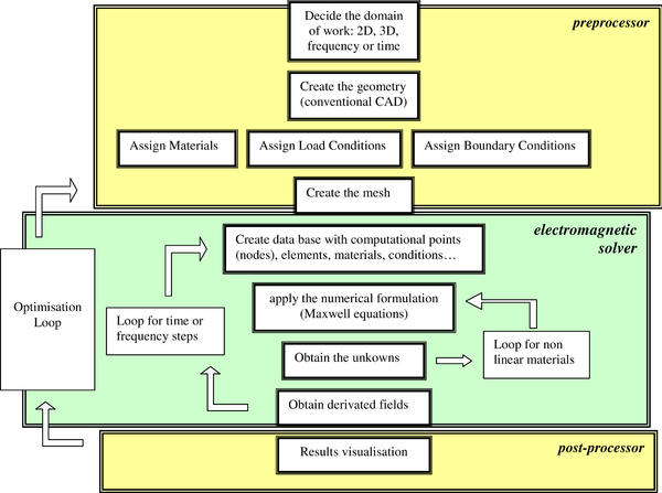
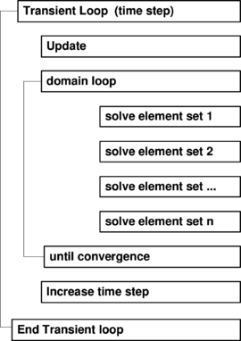
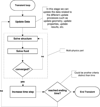
In terms of a flux diagram, we have:
This diagram can be extended if we need to move the geometry, change the load conditions or adapt to any other aditional method or external program (parallel computing, circuit design, etc).
Traditional Computing Solutions
From the point of view of the code, we can classify the methods in the time domain (TD, adequate to obtain transient solutions) or frequency domain (FD, when the sinusoidal mode is enough). Depending of the equations to be solved (the mathematical formulation), a simplified list could be [2]:
Differential Equation Methods
Based on the direct discretisation of the differential equations.
FDTD (Finite Difference Time Domain), FDFD(Finite Difference Frequency Domain).
Advantages
- Easy of implementation;
- Simple and precise (we solve directly the equations involved in our problem);
- Sparse matrix (the linear system generated is almost diagonal, making possible a fast and precise resolution);
Disadvantages
- Strong limitations to use complex geometries (the only mesh allowed has to be a regular grid);
- It needs artificial boundary conditions to limit open domains, and to accomplish the Sommerfeld radiation condition;
Variational Methods
Based on the variational formulation of Maxwell’s equations.
MoM (Method of Moments), FEM (Finite Element Methods), FVM (Finite Volume Methods), etc.
MoM (Method of Moments), BEM(Boundary Element Method)
Advantages
- It is only necessary to solve equivalent currents in the surfaces of the problem (less number of unknowns and meshing required )
- Problems with infinite or semi-infinite domain are accurately modelled (radiation conditions are naturally included in the Green functions); -
- Easily adapted to complex geometries;
Disadvantages
- Full matrix (high computing cost);
- The Green functions for the specific problem should be obtained;
- Difficult to work with non homogeneous and non linear;
FEM (Finite Element Method).
Advantages
- General and flexible (it does not require the knowledge of Green fuctions for every problem);
- Easy to work with not linear behaviors and unhomogeneous materials;
- Sparse matrix (linear system can be solved efficiently using iterative or direct sparse algorithms);
- It works very well with complex geometries;
Disadvantages
- Sommerfeld´s radiation condition has to be approximated in an artificial boundary;
- It is needed to mesh the whole domain of the problem;
- Hardware demanding;
Asymptotic methods
Based on the approximation of the Maxwell equation. It do not solve the full Maxwell set of equations.
Ray-tracing, etc):
GO (Geometric Optics), GTD (Geometric Theory of Diffraction), UTD (Uniform Theory of Diffraction), UAT (Uniform Asintotic Theory), PTD (Physical Theory of Diffraction).
Advantages
- Extremely efficient;
- Not too much hardware resources are needed;
- It is not necessary a specific mesh;
- Very short computing times;
Disadvantages
- They are based on approaches;
- Presence of singularities;
Hybrid methods
FEM-MoM, FDTD-FEM, GTD-FEM
Blend of two or more methods which takes advantage of their most remarkable features and minimize their weakest points.
Transversal Computing Solutions
Additionally to the topics previously mentioned, there are other important efforts to complement the simulation programs with transversal capabilities as, for example, the advances in parallel computing and grid computing, the possibilities of the remote computing (strongly linked to the previous feature).
These technologies, easily adapted to any simulation program, as external plug-ins, are also quite close to other artificial intelligence methods, such as neural networks, to include optimisation loops in the simulation procedures, and multi-agent engines, for the management of the grid computing resources. Extending this concept, new simulation methods can be guess for the future, by combining the traditional numerical methods above classified with the new multi-agent paradigms [3, 4].
Criteria for the Selection of Methods
In summary, after the above classification, the important questions that the developer (or buyer), should have to answer are:
Requeriments of the physical solution: quantitative or qualitative
It is usual to associate qualitative solutions for academic exercises and quantitative ones for the professional world. But a more or less precise solution is not always depending on this direct classification, as presented in the introduction.
Dynamic of the problem: static, quasistatic, low or high frequency dynamic
Most of the problems of interest are dynamics, but due to the high cost of the different time and/or frequency steps, it is important to consider if the real parameter to obtain is directly related with the dynamics of the problem. There are a huge number of designs that can be decided using static solutions (or just the values for one frequency, under the sinusoidal mode approach).
One, two or three dimensional domain
The real world is three dimensional, but some important electromagnetic structures can be defined using a two or even one dimensional domain: planar structures, transmission lines, axysimmetric geometries, etc.
Open or close problem domain
The kind of domain can strongly determine the numerical method. For open domains is usual to work with the method of moments, and for close domains can be better to work with finite element methods.
Time or frequency domain
Time domain is used when we are interested in transient behaviour (as in lightning stroke simulation, transient eddy curents, etc ) . Frequency domain is suitable when we are interested in the sinusoidal steady state analysis as such in aerial design, microwave circuits design, etc.
Linear or Non Linear Materials, with or without losses
Full wave problems have been traditionally solved with boundary methods, usually only in presence of perfect conductors. Considerations of materials with losses, or non linearities are easier to solve with finite elements, where inhomogeneities and non linearities are naturally consider in the formulation. Non linearities also increase the computation time by adding an additional loop to find the working point of the material.
Finally, is also clear that other very important question is related to which one will be the application, already mentioned.
Application: electrical machines, transmission lines, electronic circuits, antennas…
General Computing Tools
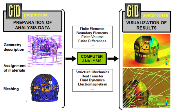
An Universal Pre and PostProcessing Solution: GiD
One of the most critical and time consuming problems for the numerical simulation is the selection of a good simplified geometrical model, the creation of an appropriate mesh [5] and processing of the results, in the sense of finding a fast presentation of the million of unknows obtained (quick visualisation, combination of variables, etc). All this problems are responsibility of the pre and postprocessing software, and are common not just in most of the electromagnetic problems, but also in other engineering disciplines.
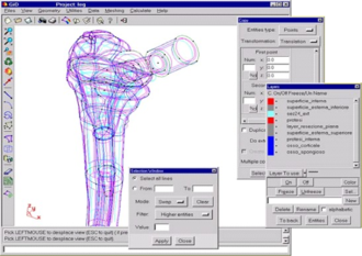
GiD [6] was developed at CIMNE, the International Center for Numerical Methods in Enginnering, as result of the demands of our own numerical methods experts, coming from different fields (civil, industrial, naval or aeronautic engineers). Each of them required specific geometrical and mesh specifications, to be used with their own mathematical formulation and computing codes. Therefore, the initial requirements for GiD included a common interface to handle complex 2D and 3D geometries, easily labeled with material properties and conditions, and prepared to export the mesh data linked with all the problem information to their solvers.
After near ten years of development, GiD is used by about 10.000 scientist and engineers worldwide, and over 45,500 downloads from more than 50 countries. For this reason, one of the key aspects to be successful in a so wide range of applications is the continuous feedback with their users.
Summarising their main features, GiD is a competitive pre and post processor, universal, adaptive and user-friendly graphical user Interface for geometrical modelling, data input meshing and visualisation of results for all types of numerical simulation programs.
Typical problems that can be successfully tackled with GiD include most situations in solid and structural mechanics, fluid dynamics, electromagnetism, heat transfer, geomechanics, etc. using finite element, finite volume, boundary element, finite difference or point based (meshless) numerical procedures (visit http://gid.cimne.upc.es/2004/papers.subst to see some advanced applications of GiD, including some applications to electromagnetism).
The following are the capabilities that make of GiD a key tool for the simulation programs developers:
- Universal: GiD is ideal for generation all the information (structures and unstructured meshes, boundary and loading conditions, material types, visualisation of results, etc.) required for the analysis of any problem in science and engineering using numerical methods. Typical problems are structural analysis, fluid dynamics, etc. using finite element, finite volume or point-based (meshless) numerical procedures.
- Adaptive: GiD is extremely easy to adapt to any numerical simulation code. In fact, GiD can be adjusted by the user to read and write data in an unlimited number of formats. GiD’s input and output formats can be customised and made compatible with any existing in-house software.
- User-friendly: The development of GiD has been focused on the needs of the user and on the simplicity, speed, effectiveness, and accuracy he or she demands at input data preparation and result visualisation level. GiD has proven to be extremely useful for companies, universities, and R+D centres.
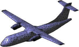
- Mesh generation options: GiD allows the generation of large meshes in a fast and efficient manner. It has structured meshes (2D triangular and quadrilateral meshes, and 3D hexahedral meshes) and unstructured meshes (2D triangular and quadrilateral meshes, and 3D tetrahedral meshes).
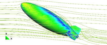
- Visualisation facilities: Deformed shapes, temperature distributions, pressure, vector and contour plots for displacements, velocities, stresses, animated sequences for dynamic analyses, scalar, vector and matrix quantities, particle line flow diagrams, user-customisable menus and Iso surface visualisations.
- GiD customisation: simple pre and post processing menus are quickly developed for existing software, including online manuals, tutorials or internet connections. Advanced customisation capabilities based on TCL/TK allow the creation of sophisticated interfaces with a wide variety of looks, skins and specific widgets.
GiD has been designed to be used in universities, research centers and companies to develop and apply different numerical simulation programs. However, in spite of its advantageous features, GiD has some limitations for electromagnetic problems, mainly due to the unavailability of non-standard (H(curl) and H(div), low and higher orders) finite elements. Nowadays, the programmer can deal with these limitations by creating their own TCL/TK functions.
There are some commercial and open source software for numerical simulations that have selected GiD as a pre and postprocessor. Good examples are Impact [7], Tochnog [8] or GiD_CEM [9], a software package for geometrical creation, simplification, cleaning and meshing of CAD models for Computational ElectroMagnetics, result of a EADS-CIMNE partnership.
A General Simulation Package Environment: Kratos
Different efforts are being done to create a single environment to deal with multi-physic problems [10, 11, 12]. The natural evolution of the current software packages is to extend their capabilities to multi-disciplinary problems, by integrating other minor programs, or by including capabilities to accept plug-ins.
This integration of disciplines, in the physical as well as in the mathematical sense, suggests the use of the modern object oriented philosophy from the computational point of view. The modular design, hierarchy and abstraction of these approachs fits to the generality, flexibility and reusability required for the current and future challenges in numerical methods.
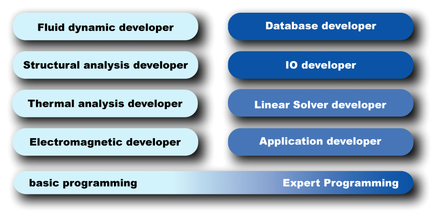
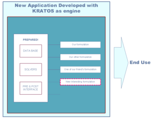
Kratos [13] has as main objective to establish a framework, methodology and computing structure to allow the building of finite element programs at different levels of implementation. For example, depending on the interest of the user the package can be used as a high level library to explore new finite element formulations or to check the features of new technical implementation of physical applications.
Summarising the main Kratos capabilities:
- Kratos is a Methodology and Computing Structure to Build Finite Element Programs: an open source framework with object-oriented structure intended to provide the tools for finite element programmers in different fields and connect them in term of solving coupled multi-physics problems.
- Kratos is a environment to work at Different Implementation Levels. It consist in a set of classes and methods for programmers to provide the ability to handle multi-physic, adaptive meshing and optimisation problems. Kratos should help to built a numerical application in C++ from the easiest formulation (conduction problem) to the most complex ones (optimisation techniques).
- Two different approachs can be done: from the user-developer point of view, considering their contribution as requirements of the Kratos system as well as plug in extensions, but also from the user-application interests, using the already existing finite element programs as calculation engine.
- Kratos is Reusable and Program Maintainable. Special attention has been put in the modular aspects of the Object Oriented Programming and in the creation of an intranet platform to share all the Kratos documentation including methodology, structure, project progress and source code.
- Kratos is Open Source. The main code and structure is free available and aimed to grow with the need of the user, under GNU Lesser General Public License and the code can be open or close depending on the developers preferences.
The major drawback of Kratos current version for computational electromagnetism is that does not work with complex numbers and that it only deals with Langrangian elements, but, in next versions, both problems are planned to be solved. Also, Kratos includes the possibility of using phyton to interact with the database on run time, in order to extend their set of functions to be adapted to the user requirements.
General Electromagnetic Simulation Package
EMANT: [14] is the result of integrate Kratos and GiD as a single package for electromagnetic analysis [15].
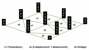
The main requirements for EMANT, as a numerical code for solving Maxwell’s equations, based in the finite element method formulation [16], is to take advantage of all the Kratos features but considering the peculiarities of the electromagnetic problems [17, 18]. Therefore, the major difference between Kartos, as a general tool, and EMANT as electromagnetic one, is the need of an specific database for complex numbers, and functions to work in the frequency domain.
The progress in the EMANT features goes from static and quasistatic problems in the time domain, based in the Poisson equation, quite similar to the thermal or structural ones, to those for full wave propagation, in the frequency domain, where a new formulation is needed. For the first case, electro-thermal coupled and typical eddy current problems has been successfully tested, and can be easily integrated in other Kratos modules such as the fluid dynamic or structural ones, of high interest for electrical machines, or food processes.
A full wave 2D electromagnetic module is free available in [XX], with some examples of use and an user manual. The three 3D modules have been also already developed, but due to the limitations of the finite element method (FEM) for open problems, new hybrid formulations combining the Method of Moments with the FEM is being developed.
The future challenges for EMANT is to combine different methods (BEM-FEM or GTD-FEM) to solve complex electromagnetic problems, where the open geometries are solved using boundary elements but with specific areas, the sources for example, working with the finite element method, or in those places where non metalic materials has to be used.
Additionally, taking advantage of Kratos inherent modularity, EMANT is intended to cope with multi-physics coupled problems, such as thermal dissipation in the packaging of circutis.
The current version has been designed mainly for research and academic purposes, to help students, scientist and engineers to calculate electromagnetic fields in a wide variety of practical situations, helping also to reach a deeper knowledge of electromagnetic phenomena by showing fields behavior visually.
Conclusions
A summary of the current developments on computational electromagnetism has been reviewed, and a list of the common needs is obtained by comparing the most usual electromagnetic problems. As a result, three general computer tools are presented to cover these requirements, their advantages and drawbacks. The main feature of these programs is that they can be used to craft customised numerical simulation programs: GiD for geometrical modeling, data input and visualisation of results. Kratos as starting point for a C++ finite element code, and finally, EMANT, as an example of how to blend Kratos and GiD to analyse electromagnetic problems.
References
[1] P.P. Silvester and R. L. Ferrari, Finite Elements for Electrical Engineers, Cambridge University Press, 1983
[2] F. Reitich and K. K. Tamma, State-of-the-art, trends and directions in Computational Electromagnetics, CMES Comput. Model. Eng. Sci. 5 (2004), 287-294
[3] S. Bieniasz, K. Cetnarowicz, E. Nawarecki, S. Kluska-Nawarecka: Agent-based Simulation in Finite Element Environment. Management and Control of Production and Logistics. IFIP, IFAC, IEEE Conference, ENSIEG, LAG Grenoble, France 2000
[4] Gilbert Peffer and Javier Mora, “Multi-Agent Scientific Computing”, VI Symposium on Artificial Intelligence –AI-METH 2005, Gliwice (Poland), 16, 17 and 18 November 2005
[5] Joseph George Ferrante, “Geometrical and Electromagnetic Modelling for Aerospace Engineering”, 2nd Conference on Advances and Applications of GiD, Barcelona, Spain, 18, 19 and 20 February 2004
[6] GiD:Personal Pre and Post Processor. http://www.gidhome.com . International Center for Numerical Methods in Engineering (CIMNE)
[7] Impact: A Free Explicit Dynamic Finite Element Program, http://impact.sourceforge.net/
[8] Tochnog: A Free Explicit/Implicit Finite Element Program, http://tochnog.sourceforge.net/
[9] GID-CEM: Geometrical Creation, Simplification, Cleaning and Meshing of CAD models for Computational ElectroMagnetics, http://www.aseris-emc2000.com/products/gid_cem/index.php
[10] POOMA: Parallel Object-Oriented Methods and Applications, http://acts.nersc.gov/pooma/
[11] deal.II: A Finite Element Differential Equations Analysis Library, http://www.dealii.org/
[12] Femlab: an interactive environment for modeling scientific and engineering applications, http://www.comsol.com/products/femlab/
[13] KRATOS: An Object-Oriented Environment for Development of Multi-Physics Analysis Software. http://www.cimne.com/kratos . International Center for Numerical Methods in Engineering (CIMNE)
[14] EMANT-Kratos: Electromagnetic Analysis with Numerical Tools using a Multi-Physics Object-Oriented Environment Software. http://www.cimne.com/kratos/emant . International Center for Numerical Methods in Engineering (CIMNE)
[15] Rubén Otín, Javier Mora and Eugenio Oñate, EMANT: Integration of GiD and Kratos, Open and Flexible Computational Tools, 2005 IEEE/ACES International Conference on Wireless Communications and Applied Computational Electromagnetics, April 3-7, 2005, Hilton Hawaiian Village, Honolulu, Hawaii
[16] J. Jin. The Finite Element Method in Electromagnetics. John Wiley & Sons, 2002
[17] C. Hazard and M. Lenoir. On the solution of the time-harmonic scattering problems for Maxwell’s equations. SIAM Journal on Mathematical Analysis, 27:1597–1630, 1996
[18] Bo-Nan Jiang, Jie Wu, and L.A. Povinelli. The origin of spurious solutions in computational electromagnetics. Journal of Computational Physics, 125:104–123, 1996
Document information
Published on 01/01/2005
Licence: CC BY-NC-SA license
Share this document
Keywords
claim authorship
Are you one of the authors of this document?
