Abstract: Dynamic characterization of structures from field measurements is useful for different purposes (e.g. retrofit validation, model updating, structural health monitoring, etc.). The identification of high spatial density mode shapes has been recently a challenge tackled using mobile sensors. These sensors travel over the structure and continuously acquire vibration data that is used to identify modal coordinates with a higher spatial density than can generally be obtained using a limited number of stationary sensors. The recorded signal from a mobile sensor is non-stationary, thus, it has significant variations in its spectral content over time, requiring a suitable processing to extract the properties not only for the time but also for the frequency domain. In this paper, Cohen’s class Time-Frequency Distributions (TFD) are proposed for the output-only dynamics identification of structures based on non-stationary signals recorded with mobile sensors. Identification is achieved through cross-time-frequency estimators using Smoothed Pseudo-Wigner-Ville (SPWVD) distribution. Results from numerical simulations using a simply supported beam subject to ambient vibration are shown and the sensibility of the proposed identification to the presence of measurement noise is evaluated. Numerical results show that use of the cross-time-frequency estimators is effective in extracting modal properties of the structures and filtering noise.
Keywords: Modal Identification, Mobile Sensors, Non-Stationary Signals, Time-Frequency Distributions
1. Introduction
Structural Health Monitoring (SHM) Systems usually play a crucial duty in early failure or damage detection for construction, maintenance or catastrophe management. Civil infrastructure and many other sectors can greatly benefit from systems that monitor behaviour under normal operating conditions, without the need of interrupting regular day-to-day activity (Brownjohn, 2007; Karbhari et al., 2009).
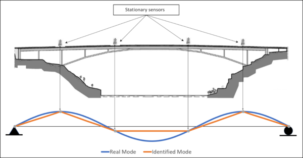
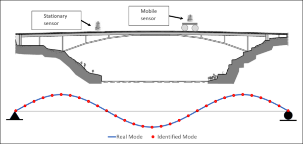
The future trend in instrumentation for SHM is the use of smart mobile sensing along with wireless intelligent networks, as they not only provide similar information to conventional cabled systems, but can also be installed at a much lower cost and process data autonomously using their embedded microprocessors and software (Lynch, 2006; Spencer et al., 2004). Modal shapes are traditionally identified with stationary sensors fixed at locations that provide representative structural responses, however, these schemes contain restricted spatial information (Figure 1). If more spatial and temporal data is obtained from a vibrating structure, the structure’s response can be evaluated more accurately, and hence the advantage of implementing the structure with as many stationary sensors as possible during the acquisition of data. However, despite the improved accuracy in estimations, these or dense sensor array approaches can be impractical for many reasons including the cost of sensors and setup time, memory constrains, network reliability, power requirements, and physical limitations due to structure geometries (Magalhães et al., 2008, 2009; Matarazzo T. J. and Pakzad, S. N. 2013). Mobile sensing is a novel alternative in Structural Health Monitoring (SHM). The objective is to solve failings from fixed sensor array setups. Few sensors are usually used to collect dense spatial information in mobile sensing setups. Mobile sensing provides several advantages over schemes using stationary sensors, but the main advantage is that a single mobile sensor can be used to record signals continuously along the structure. Modal coordinates are identified with a higher spatial density than using stationary sensors because the mobile sensor continuously records vibration data as it travels along trajectories on the structure (Figure 2). Mobile sensing is not only easier to implement, but also more cost effective when compared to dense stationary sensor arrays (Marulanda et al., 2016; Marulanda, J., 2014; Matarazzo T. J. and Pakzad S. N., 2013).
Recent implementation of mobile sensor networks has been diverse, although limited, and is still under development. Zhu et al. (2010, 2012) proposed a sensing device. Such device will record data at selected nodes, but will not do so while the sensor is moving. Sibley et al. (2002) and Dantu et al. (2005) implemented Robomote, miniature low cost robots for mobile sensors networks. Partial modal identification include the use of a moving vehicle to identify frequencies of a single span bridge using frequency domain techniques (Cerda F. et al., 2012; Lin and Yang, 2005). Marulanda et al. (2016) and Marulanda (2014) developed a novel technique that uses two sensors, one mobile and the other stationary, in which the mobile sensor records continuously, and, in a subsequent procedure, performs the modal identification through spectrograms. Matarazzo et al. (2014, 2016) proposed a method of collecting data through continuous mobile detection in the presence of missing time and space observations. As the corresponding matrices have incompatible data records, they developed and successfully implemented an algorithm, called STRIDE, to cover for such “empty spaces”.
The use of mobile sensors, typically accelerometers, require an analysis of non-stationary response signals. Time-Frequency analysis has been proposed by several authors to analyse non-stationary responses in structural identification and in the assessment of mechanical damage. Staszewski et al. (1994) and Rioul et al. (1991) have devoted several papers to modal identification using the Short-Time Fourier Transform (STFT) and Wavelet Transform (WT). The STFT transforms the signal in a two-dimensional time-frequency plane, assuming that the signal is stationary when viewed through a limited extension window. The Fourier Transform of the windowed signal leads to a time-frequency distribution (Gabor, 1946; Arango, 2009; Oppenheim, 2010). The STFT is linear and therefore provides poor energy information about the signal. Quadratic Time-Frequency Distributions (TFDs), on the other hand, allow the interpretation of representations from a much richer energy point of view (Hlawatsch and Boudreaux-Bartels, 1992; Loughlin et al., 1993). Marginal properties express such interpretation. However, in view of the Uncertainty Principle, such properties are not sufficient to identify an energy density at each point on the time-frequency plane. (Ceravolo, 2009). A spectrogram, or quadratic representation of the amplitude of the STFT, is a three dimensional representation of the time-averaged Fourier Transform over adjacent time segments of a random process (Bendat and Piersol, 2011). It does not fulfil marginal properties and violates the Linearity Principle, generating crossed or interference terms. These spurious terms are restricted to those regions of the time-frequency domain where the auto-terms overlap. In the specific case of the spectrogram, for two sufficiently separated components in the time-frequency plane, its interference terms are practically nil (Ceravolo, 2009). Spectrograms can be used to obtain modal coordinates from the signals recorded from a mobile and a stationary sensor. These signals are divided into quasi-stationary segments and then the auto-spectral density and cross-spectral density functions for segments of both records are calculated. Finally a modal identification procedure is performed (Marulanda et al., 2016; Marulanda, J, 2014).
In this paper, the non-stationary signals analysis recorded from sensors is performed by using Cohen’s class TFDs. The adoption of a quadratic representation helps in overcoming the limitations from time-frequency resolution, as these transformations, the energetic and the correlative, are not based on the segmentation of signals. (Cohen, 1995). Invariance to time and frequency shifts characterize the Cohen’s Class Distributions (Hlawatsch and Auger, 2013). The system response is recorded in the time-frequency plane as the evolution of the spectral components corresponding to the energy of individual vibration modes whenever the Cohen’s Class Distributions is in use (Bonato et al., 1998, 1999; Bonato et al., 2000; Bonato P. et al., 1997; Cohen, 1995; Hammond and White, 1996; Hlawatsch and Boudreaux-Bartels, 1992). The proposed technique assumes that the frequency range of the system input spans the vibration modes. As the input spectrum increases, so does the identification accuracy. The instantaneous amplitude ratios directly determine the modal amplitude ratios for the time-frequency representations of signals recorded from a mobile sensor and a stationary sensor. Additionally, the phase of the cross-time- frequency representation between the two signals estimate the phase relationships. The estimators retain their dependence on time since they are derived directly from the two-dimensional functions of frequency and time variables. modal responses in linear time invariant systems show a constant relationship between the amplitude and the phase, and, therefore, the identified mode shapes are characterized by their stability over time (Bonato et al., 1998).
2. Theoretical Background
Cohen’s Class Distributions
Cohen’s class distributions display a clear invariance of their representations for time and frequency shifts, a desirable property when correlating signal characteristics to phenomena occurring in the physical system generating the signal. The following equation describes all the Cohen’s class distributions (Hlawatsch and Auger, 2013):
|
|
(1) |
where is the signal, is its complex conjugate, is time, is frequency and is the time delay, is the circular frequency; is the kernel of the distribution and is the Cohen Class TFD. The cross-time-frequency distribution between two signals and can be defined as follows:
|
(2) |
The Wigner–Ville distribution (WVD) is the basic TFD and is a quadratic form that measures a local time-frequency energy. This distribution is obtained from equation (1) using . Although the WVD satisfies a several important mathematical properties (Bonato et al., 2001; Flandrin, 1984; Wang and McFadden, 1993), it is not very suitable for applications with multiple components signals since the bi-linearity of the transform causes the appearance of interference terms . These are spurious terms when using the time-frequency characteristics of the signal for modal identification. The smoothed pseudo-Wigner-Ville transform (SPWVD) results from , where and are the standard deviations in time and frequency, respectively. With the exception of real value, time-shift-invariance, and frequency invariance, the application of the smoothed function causes the loss of most of the mathematical properties of the WVD, (Hlawatsch and Boudreaux-Bartels, 1992). The foregoing independence between windows makes the SPWVD very versatile for reducing cross—terms in the WVD. This property is useful for modal identification.The Choi-Williams Distribution (CWD) (Choi and Williams, 1989; Papandreou and Boudreaux-Bertels, 1993) is defined by . This kernel is defined in the ambiguity plane . If is very large, the kernel vanishes, therefore leading to the WVD, otherwise, the kernel application will have a filtering effect. For small values of , the effect of the multiplication is to preserve the ambiguity function close the origin of the plane , therefore, this kernel satisfies the minimization property (Cohen, 1995). In multicomponent signals the authentic terms are usually close to the ambiguity plane axis, and the interference terms are dispersed away. The resulting characteristic function reduces the interference terms without significantly affecting the signal components (Bonato et al., 1997). Therefore, although the CWD violates the time and frequency support properties, it can be shown that the introduced error is generally negligible (Lippmann, 1989; Papandreou and Boudreaux-Bertels, 1993), so the value should be adapted to each individual case, since the location of the interference terms and the signal components change with respect to the characteristics of the signal (Bonato et al., 1997). In this paper, SPWVD distribution is used. In this case, by parameterizing the windows, as they attenuate the interference terms without significantly modifying the signals, good modal identification results are obtained.
Modal Identification Using Mobile Sensors
The proposed methodology requires a mobile sensor that acquires data continuously along the structure to be identified and simultaneous acquisition by a stationary sensor. Under ambient excitation using a zero mean Gaussian white noise process, the outputs of the system are also zero mean Gaussian processes, exciting the fundamental frequencies (Bendat and Piersol, 2011). Since the recorded signal from the mobile sensor is non-stationary, a procedure based on the Cohen Class Distributions (i.e. SPWVD) is proposed. These distributions are invariable to time and frequency shifts, which is required for proper system identification.
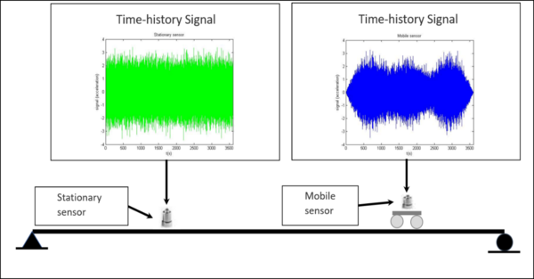
Assuming that the structure to be identified is the one-dimensional beam shown in Figure 3 has discrete degrees of freedom (d.o.f.), wich each d.o.f. corresponds to a segment of the signal from the mobile sensor (Figure 4).
Let be the response (displacement) in the th position of the system, the response (displacement) associated with the th vibration mode, and a term of the normalized eigenvectors matrix, then can be in decouple form as,
|
|
(3) |
The term of the sum in equation (3) extends to the vibration modes that are detected in the th position corresponding to a discretized d.o.f. The structure under ambient excitation is equipped with a mobile sensor with constant velocity that continuously records the acceleration and, simultaneously, with a stationary sensor also recording the acceleration vibrations. For each d.o.f., the individual modal components appear in the form of an energy peak in the time-frequency plane that can be written in complex form as (Bonato et al., 2000):
|
|
(4) |
where is a baseband signal related to the mode; and are the amplitude and phase modulation waveforms respectively; is the natural frequency; is the amplitude of the mode shape in the position. The complex form of equation (4) represents an analytical signal and, therefore, the spectrum of is single-sided. The WVD will transform the signal into:
|
(5) |
where is the WVD of the signal , is the convolution in frequency, and ) is the Dirac delta (impulse) located in . In multi-component signals, when auto-terms and interference overlap, using a kernel capable of attenuating interference terms leads to an increased reliability of the estimated amplitude ratio. The use of highly selective kernels, ambiguity domain functions (Bonato et al., 2000), improves the capacity of the cross-time-frequency-transform to separate signal components, and therefore, allow amplitude ratio and phase difference estimators become close to each modal shape frequency.
The following expression represents the Cohen’s Class Transforms:
|
|
(6) |
where is a Cohen class TFD, is the kernel of the TFD in time-frequency plane. is the double convolution in time and frequency. From equation (6) it is evident that the energy of the transform concentrates close to the modal frequency . The distribution shape is determined by the time-frequency transform of the modulating waveform . Because the shape of the modulated waveform is kept in the time–frequency domain. The amplitude ratio between two modal components can be determined from auto-time-frequency representations, as follows (Bonato et al., 1998; Bonato et al., 2000):
|
|
(7) |
And the phase can be deteremined from cross-time-frequency representtions, as follows:
|
|
(8) |
The TFDs of the signals from both sensors, mobile and stationary, were used in separating modal and residual components and in estimating the modal Amplitudes Ratios (AR); while cross-time-frequency representations were used in estimating the Phase Ratios (PR) (Bonato et al., 1998). The system is displayed in the time-frequency plane as the unfolding of spectral components corresponding to the energy of the predominant vibration modes. The ARs, gathered from their time-frequency representations, are determined from the ratio between the instantaneous amplitudes of the signal segments. The PRs are the ratio between the imaginary and the real part of the cross- time-frequency representation of two signal segments (Bonato et al., 2000). Once the cross terms have been filtered, it is possible to identify a potential error source in the vibration modes due to a close coupling between the components. In contrast to classical frequency analysis, the cross time-frequency transform between channels can filter the products among various components. Although being closely coupled in frequency, they are uncorrelated in time (Bonato P. et al., 1997).
In the frequency ranges in which a single modal component is predominant, the estimators tend to be a constant value over time. Because the variance ( ) is a measure of the density of the time-frequency representation, the peaks of the variance of the cross-time-frequency transform are concentrated close to fundamental frequencies and, therefore, such frequencies are located in the maximum of the following function:
|
|
(9) |
where is the length of the signal, and indicates the mean value of the cross-time-frequency distribution.
3. Numerical Simulations
A proposed example to evaluate the described procedure using a numerical model of a simply supported beam (Figure 3). The beam’s th natural vibration mode shape and corresponding natural frequency are given by the following equation:
|
(10) |
where is the total length of the beam, is the elasticity modulus of the material, is the moment of inertia of the cross section, and is the constant mass per unit length (Chopra, 2012). In the following numerical simulations. In this simulation is assumed that , , , , and ; and, therefore, the first three natural frequencies of the beam are , , and . The stationary sensor was located at from the left support and the mobile sensor had a velocity of . The excitation of the beam corresponds to a Gaussian white noise acceleration at the supports. The simulated response signals were sampled at , and then conditioned using a Hilbert transform and sub-sampled at . SPWVD was used for the modal identification. The computed SPWVD was performed with a Hanning time smoothing window of samples, Hanning frequency smoothing window of samples and 256 frequency bins. The identified mode shapes are compared to the exact mode shapes using the Modal Assurance Criterion (MAC) via equation (11) (Pastor et al., 2012). The damping is identified using the Half-Power Bandwidth method (Bonato P. et al., 1997; Chopra, 2012). The influence of noise in the identification is evaluated. The software used for signals processing using TFDS was The Time-Frequency Toolbox (TFTB) (Auger F. et al., 1996).
|
|
(11) |
TFD-based mode shapes identification
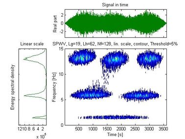
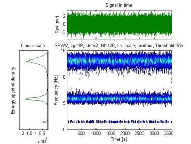
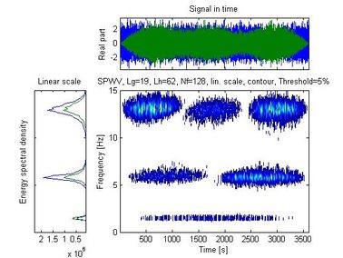
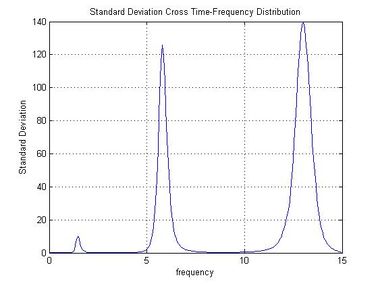
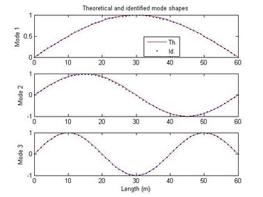
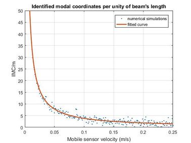
Figure 5 shows the time history of the signal recorded with the mobile sensor traveling at 0.0167 m/s, along with the spectral density and auto-SPWVD. Figure 6 shows the time history of the signal recorded with the stationary sensor, along with its spectral density and auto-SPWVD. Figure 7 shows the time history of the signals recorded with the mobile and the stationary sensors along with their spectral density and cross-SPWVD. Figure 8 shows the standard deviation of the cross-SPWVD. The modal frequencies and damping ratios were obtained via Equation (9) by selecting peaks and using the Half-Power Bandwidth method (Figure 8). The mode shapes were obtained from TFDs (i.e. SPWVD), as given by Equations (7) and (8). Table 1 summarizes results of the modal parameter identification, where it is shown that errors in natural frequencies are generally less than 1.5 %. The identified mode shapes are also compared to the exact mode shapes. In this example, 59 modal coordinates were identified, and MAC values were all equal to one for the first three modes (Figure 9). MAC values for different mobile sensor velocity values, ranging from to , were calculated. Figure 10 shows the variations in the identified modal coordinates (IMC) per unity of beam’s length versus the mobile sensor’s velocity, it is assumed that two modes are considered correlated when the MAC value is equal to 0.95, which corresponds to an angle of 18 degrees (Pastor et al., 2012). From Figure 11, it can be observed that good identification results have been obtained from the simulated ambient response data contaminated with different intensity levels of white gaussian noise.
| MODE | Theoretical frequencies
(Hz) |
Identification by TFD (SPWVD) | Frequency Error
(%) | ||
| Natural
frequencies (Hz) |
Damping
ratios |
MAC
values | |||
| 1 | 1.450 | 1.465 | 0.060 | 1.00 | 1.03 |
| 2 | 5.798 | 5.801 | 0.029 | 1.00 | 0.05 |
| 3 | 13.046 | 13.008 | 0.025 | 1.00 | 0.29 |
Signal-to-Noise Ratio
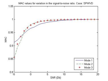
In most experimental applications, the acceleration record from the mobile sensor would be more contaminated with noise than the stationary sensor due to the motion system. To evaluate the effect of such noise on the identified modes through the MAC values, artificial normally distributed white noise was added to the acceleration response of the mobile to generate signal-to-noise ratios from -5 to 20 dB. Figure 11 shows the MAC values versus SNR for the first three identified modes. It can be seen from Figure 11 that the identification accuracy of all mode shapes can be maintained at a high level using the proposed method for SNR values higher than 15 dB.
4. CONCLUSIONS
This paper presents the use of mobile sensors for modal identification through Cohen’s Class TFDs, providing identified modal shapes with high spatial resolution. Mobile sensors can be used in structures and mechanical systems under normal operating conditions and unknown excitation. It is envisaged that mobile sensors not only offer flexible but adaptable spatial resolutions that may enhance the theory and practice of future SHM and damage detection research and technological development.
The mobile sensor continuously records vibration data as it travels along trajectories on the structure, therefore, modal coordinates are identified with a higher spatial density than using stationary sensors. The quantity of identified modal coordinates depends on the velocity of the sensor, the selected kernels, and the identified frequencies.
The TFD-based modal identification utilized to identify the structural system in terms of natural frequencies, damping ratios and mode shapes, along with the use of mobile sensors complied successfully. The mode shapes are estimated through the auto and cross time-frequency transforms of the signals from mobile and stationary sensors (i.e. modulating waveforms). The proposed methodology is highly accurate when calculating mode shapes by determining the amplitude and phase ratios between TFDs of signals recorded with the mobile and the stationary sensors, respectively. The standard deviations of cross time-frequency transforms of the recorded signals are related to modal frequencies and damping ratios.
The effectiveness of the technique is clear, based on auto and cross-time-frequency estimators for structural identification when non-stationary signals are used. For velocities between to , the variations in the identified modal coordinates per unity of beam’s length ranges from to . For a velocity of , 59 modal coordinates were identified, and MAC values were all equal to one for the first three modes using only two acceleration records. For signal-to-noise ratios higher than 15 dB, all identified modal shapes are noise stable.
REFERENCES
Auger F., Flandrin P., Goncalves P., and Lemoine O (1996), “Time-Frequency Toolbox for Use with MATLAB Reference Guide”, Centre National de la Recherche Scientifique.
Auger F., Flandrin P., Goncalves P., and Lemoine O (1996). “Time-Frequency Toolbox for Use with MATLAB Tutorial” Centre National de la Recherche Scientifique.
Bendat, J.S., and Piersol, A.G. (2011), “Random Data: Analysis and Measurement Procedures”, John Wiley & Sons.
Bonato P., Ceravolo R., De Stefano A., and Knaflitz M. (1997), “Bilinear Time-Frequency Transformations in The Analysis of Damaged Structures”, Mech. Syst. Signal Process., vol. 11, no. 4, pp. 509–527.
Bonato, P., Ceravolo, R., De Stefano, A., and Molinari, F. (1998). “Time-frequency and cross-time-frequency based techniques for the structural identification of systems”, Proceedings of the IEEE-SP International Symposium on Time-Frequency and Time-Scale Analysis, 1998, pp. 445–448.
Bonato, P., Ceravolo, R., De Stefano, A., and Molinari, F. (1999). “Adaptive kernel cross-time-frequency transformations for the identification of structural systems”, SPIE Vol. 3807 pp. 582–590.
P. Bonato, R. Ceravolo, A. De Stefano, and F. Molinari (2000), “Use of Cross-Time–Frequency Estimators for Structural Identification in Non-Stationary Conditions and Under Unknown Excitation”, J. Sound Vib., vol. 237, no. 5, pp. 775–791.
Bonato, P., Roy, S.H., Knaflitz, M., and Luca, C.J. de (2001), “Time-frequency parameters of the surface myoelectric signal for assessing muscle fatigue during cyclic dynamic contractions”. IEEE Trans. Biomed. Eng. 48, 745–753.
Bonato P., Ceravolo R., and De Stefano A. (1997). “Time-Frequency and Ambiguity Function Approaches in Structural Identification”. J. Eng. Mech. 123, 1260–1267.
Bonato P., Ceravolo R., De Stefano A., and Molinari F. (1998), “A New Cross-Time-Frequency Method for the Structural Identification of Mechanical Systems in Non-Stationary Conditions”, NATO Advanced Study Institute on Modal Analysis and Testing (Sesimbra, Portugal), pp. 725–741.
Brownjohn, J.M.W. (2007), “Structural health monitoring of civil infrastructure”. Philos. Trans. R. Soc. Math. Phys. Eng. Sci. 365, 589–622.
Ceravolo, R. (2009), “Time–Frequency Analysis”. Encyclopedia of Structural Health Monitoring, John Wiley & Sons.
Cerda F., Garret J. H., Bielak J., Rizzo P., and Barrera J. (2012). Indirect structural health monitoring in bridges: scale experiments. Proceedings of the Seventh International Conference on Bridge Maintenance, Safety and Management. Lago di Como.
Choi, H.-I., and Williams, W.J. (1989), “Improved time-frequency representation of multicomponent signals using exponential kernels”, IEEE Trans. Acoust. Speech Signal Process. 37, 862–871.
Chopra, A.K. (2012). “Dynamics of structures: theory and applications to earthquake engineering”, Prentice Hall, Boston.
Cohen L. (1995), Time-frequency Analysis, Englewood Cliffs, N.J: Prentice Hall PTR.
Dantu, K., Rahimi, M., Shah, H., Babel, S., Dhariwal, A., and Sukhatme, G.S. (2005). Robomote: enabling mobility in sensor networks. In IPSN 2005. Fourth International Symposium on Information Processing in Sensor Networks, pp. 404–409.
Flandrin, P. (1984). “Some features of time-frequency representations of multicomponent signals”. In Acoustics, Speech, and Signal Processing, IEEE International Conference on ICASSP ’84., pp. 266–269.
Gabor, D. (1946). “Theory of communication” Institution of Electrical Engineering, London.
Hammond J. K. and White P. R. , “The Analysis of Non-Stationary Signals Using Time-Frequency Methods”, J. Sound Vib., vol. 190, no. 3, pp. 419–447, Feb. 1996.
Hlawatsch, F., and Auger, F. (2013). “Time-Frequency Analysis”, John Wiley & Sons.
Hlawatsch, F., and Boudreaux-Bartels, G.F. (1992). “Linear and quadratic time-frequency signal representations”. IEEE Signal Process. Mag. 9, 21–67.
Arango H. (2009), “Análisis de señales con las transformadas de Fourier, Gabor y Onditas”. Instituto Tecnológico Metropolitano, Medellín, Colombia, 2009.
Karbhari, V.M., Guan, H., and Sikorsky, C. (2009). “Operational modal analysis for vibration-based structural health monitoring of civil structures”. Structural Health Monitoring of Civil Infrastructure Systems, (Woodhead Publishing), pp. 213–259.
Lin, C.W., and Yang, Y.B. (2005). “Use of a passing vehicle to scan the fundamental bridge frequencies: An experimental verification”. Eng. Struct. 27, 1865–1878.
Lippmann, R.P. (1989). “Pattern classification using neural networks”. IEEE Commun. Mag. 27, 47–50.
Loughlin, P.J., Pitton, J.W., and Atlas, L.E. (1993). “Bilinear time-frequency representations: new insights and properties”. IEEE Trans. Signal Process. 41, 750–767.
Lynch, J.P. (2006). “A Summary Review of Wireless Sensors and Sensor Networks for Structural Health Monitoring”. Shock Vib. Dig. 38, 91–128.
Magalhães, F., Cunha, Á., and Caetano, E. (2008). “Dynamic monitoring of a long span arch bridge”. Eng. Struct. 30, 3034–3044.
Magalhães, F., Cunha, Á., and Caetano, E. (2009). “Online automatic identification of the modal parameters of a long span arch bridge”. Mech. Syst. Signal Process. 23, 316–329.
Marulanda, J., Caicedo, J.M., and Thomson, P. (2016). “Modal Identification Using Mobile Sensors under Ambient Excitation”. J. Comput. Civ. Eng. 04016051.
Marulanda J. (2014), “Modal Identification Using Smart Mobile Sensing Units”. Programa Editorial Universidad del Valle. Cali, Colombia.
Matarazzo, T.J., and Pakzad, S.N. (2014). “Modal Identification of Golden Gate Bridge Using Pseudo Mobile Sensing Data with STRIDE”. Dynamics of Civil Structures, Volume 4, F.N. Catbas, ed. (Springer International Publishing), pp. 293–298.
Matarazzo, T.J., and Pakzad, S.N. (2016). “STRIDE for Structural Identification Using Expectation Maximization: Iterative Output-Only Method for Modal Identification”. J. Eng. Mech. 142, 04015109.
Matarazzo T. J., and Pakzad S. N. (2013). “Mobile Sensors in Bridge Health Monitoring”. International Workshop on Structural Health Monitoring, Stanford, CA.
Oppenheim, A.V., and Schafer, R. W (2010). “Discrete-time signal processing”, Upper Saddle River, Pearson.
Papandreou, A., and Boudreaux-Bertels, G.F. (1993). “Generalization of the Choi-Williams Distribution and the Butterworth Distribution for Time-Frequency Analysis”. IEEE Trans. Signal Process. 41, 463-.
Pastor, M., Binda, M., and Harčarik, T. (2012). “Modal Assurance Criterion”. Procedia Eng. 48, 543–548.
Rioul, O., and Vetterli, M. (1991). “Wavelets and signal processing”. IEEE Signal Process. Mag. 8, 14–38.
Sibley, G.T., Rahimi, M.H., and Sukhatme, G.S. (2002). “Robomote: a tiny mobile robot platform for large-scale ad-hoc sensor networks”. IEEE International Conference on Robotics and Automation, 2002. Proceedings. ICRA ’02, pp. 1143–1148.
Spencer, B.F., Ruiz-Sandoval, M.E., and Kurata, N. (2004). “Smart sensing technology: opportunities and challenges”. Struct. Control Health Monit. 11, 349–368.
Staszewski, W.J., and Tomlinson, G.R. (1994). “Application of the wavelet transform to fault detection in a spur gear”. Mech. Syst. Signal Process. 8, 289–307.
Wang W. J. and McFadden P. D. (1993), “Early detection of gear failure by vibration analysis I. Calculation of the time-frequency distribution”, Mech. Syst. Signal Process., vol. 7, no. 3, pp. 193–203.
Zhu, D., Yi, X., Wang, Y., Guo, J., and Lee, K.-M. (2010). “Mobile Sensor Networks: A New Approach for Structural Health Monitoring”. American Society of Civil Engineers, pp. 159–168.
Zhu, D., Guo, J., Cho, C., Wang, Y., and Lee, K.-M. (2012). “Wireless Mobile Sensor Network for the System Identification of a Space Frame Bridge”. IEEE ASME Trans. Mechatron. 17, 499–507.
Document information
Published on 28/08/19
Submitted on 20/08/19
Volume 19 (1), 2019
Licence: CC BY-NC-SA license
