1 Introduction
The aeronautic sector is an important leader when it comes to the use of composites in industry, since weight-saving is a key factor in aircrafts. Each kilogram cut means a fuel saving of roughly 900,000 € in costs over the lifetime of an aircraft [1] and each kilogram of fuel saved reduces CO2 emissions by 3.16 kg [2]. This is why around 50% of the structural weight of aeroplanes such as the Airbus A350 or Boeing 787 is today composed of carbon reinforced composites (CC) [3]. Current initiatives like the A350XWB -built with a composite share of 53 %- or the Boeing 777X -with CC wings- show that both airframers foresee increased demand for CC after the lifetime of the A380 or the 777 which have metallic wings.
However, low cost-effectiveness of the manufactured CC parts for aeronautic sector is a major showstopper for the current CC European production. So far, most of the CC parts produced for the aeronautic sector are manufactured using an autoclave process, which is a very expensive and low production rate manufacturing process. Thus, to meet the increasing demand of CC production envisaged and to maintain industrial leadership in aeronautics, it is necessary to meet advances in materials, manufacturing methods and automation procedures that are aligned towards production and/or MRO (Maintenance, Repair and Overhaul Operations) cost reduction. In order to be competitive, CC need (a) to increase the parts’ production rate and the associated automation of manufacturing processes, (b) to develop faster and more automated repair methods, in the factory for rejected parts and in field for damages generated in service, and (c) to implement advanced non-destructive techniques for the Structural Health Monitoring (SHM) of composites during manufacturing or in service.
These needs are particularly difficult to achieve when using conventional thermoset resins in autoclaves: long times are required to cure the thermoset composites and therefore their associated component manufacturing processes are mostly focused on low-medium volume productions. Moreover, the chemical bonds formed are irreversible, so once cured a thermoset CC cannot be remoulded, reshaped or dissolved and therefore its repair or recycling is extremely difficult or impossible.
It is in this context where AIRPOXY makes sense, in order to address such challenges. The aim of AIRPOXY is to reduce the production and maintenance costs of composite parts in the aeronautic sector by introducing a novel family of thermoset composites that preserve all the advantages of conventional thermosets, but can also be easily processed and repaired, and even recycled.
This is now possible thanks to a family of ground-breaking thermoset resins invented and patented by Cidetec [4] which present reversible or “dynamic” bonds. These dynamic chemical bonds enable a series of “smart” properties, creating a new generation of thermoset composites that preserve their high performance, in terms of easy fibre impregnation and overall stability, while showing new unprecedented features once the composite is completely cured, such as Re-processability, Reparability and Recyclability, called “3R”.
The AIRPOXY consortium has stablished various specific objectives. Thus, thermoforming processes previously unthinkable for thermosets are being adapted for 3R composites, in order to reduce manufacturing cost of CC parts by 35% vs autoclave, reducing processing times from hours to minutes. Faster/cheaper repair technologies in combination with structural health monitoring (SHM) are also being studied in order to reduce significantly MRO costs. Additionally, it is expected that welding process adapted for 3R composites will reduce CC bonding costs by up to 50%. Supporting tools such as simulation and life cycle assessment/ life cycle costing/ human health risk assessment (LCA/LCC/HHRA) will be applied from the early stages of design.
The project started in September 2018 and will conclude in August 2022 with the validation of the developed technologies in industrial environments. For this purpose, two demonstrators of aero-structures will be produced: a sub-component of a fan-cowl formed by a longitudinal stiffener, transversal stiffener and skin, and a sub-component of a leading-edge formed by a nose and two webs.
AIRPOXY relies on a multidisciplinary consortium of 11 partners from 6 countries: inventor and formulator of 3R composites (Cidetec), key technology providers (IVW, Eurecat, Coexpair, University of Ioannina and Altair), aircraft components manufacturers (Eire, Idec and Sonaca), standardization experts (UNE) and aeroconsultancy (Arttic).
This article shows a part of the work developed within the AIRPOXY project. Specifically describes the development of a first version of 3R composite that meets the requirements of the aeronautical sector. Firstly the resin has been formulated, then the composite laminates have been produced by Resin Transfer Moulding process (RTM) and finally their dynamic and mechanical properties have been studied.
2 Development of 3R resin
2.1 Synthesis of the resin
Dynamic polymers developed by Cidetec consist of covalent networks, which can change their topology by thermally activated bond-exchange reactions. At high temperatures they can flow like viscoelastic liquids but below the glass transition temperature (Tg) the bond-exchange reactions are frozen and the 3R resins behave like classical thermosets.
One of the the main objectives of the AIRPOXY project is to synthesize an aero grade epoxy resin that, on the one hand, is used to manufacture components using the RTM process, and that, on the other hand, is used to manufacture fully or partially cured flat panels that can later be thermoformed. In addition, to select the best formulation, several specifications defined in “D1.3 - Report on the preliminary analysis and definition of specifications for the raw materials” were taken into account. These specifications include:
- Details on the commercial materials with which the developed 3R material shall be compatible.
- Physicochemical properties related to the RTM manufacturing processes.
- Mechanical properties that the final laminates should be able to withstand.
- Requirements regarding the resistance to fluids.
- Requirements regarding the protections that would be applied in production on the 3R composites.
Table 1 shows a summary of the key specifications defined for the 3R to be synthesized. Some of them are related to the uncured resin to be processed by RTM, and some of them are related to the cured resin.
| Specification | Unit | Value |
| Viscosity | cps | < 30 |
| Gel time | min | > 60 |
| Curing time | min | < 90 |
| Tg | ºC | > 150, prefereable >170 |
| Tensile strength | MPa | 75-80 |
| Tensile modulus | MPa | 2800-3300 |
| Flexural strength | MPa | 125-135 |
| Flexural modulus | MPa | 2700-2900 |
Nine epoxy formulations were initially prepared following previously reported method by Cidetec [5], [6]. Briefly, the different epoxy networks were prepared by mixing tetra, tri and bifunctional epoxy resin in different proportion with the corresponding dynamic hardener in bulk, at temperatures between 60 ºC and 80 ºC and degassing under vacuum. The resulting viscous homogeneous liquid was poured into a metallic mold and cured in an oven at 130 ºC for 1 h, and post-cured at 180 ºC for 0,5 h. The reaction was followed by FTIR, where a complete curing was confirmed by the disappearance of the epoxide bands at 3056 and 915 cm-1. Differential scanning calorimetry (DSC) was used to confirm the complete curing of different formulations. In all cases, no residual curing exothermic peak was observed in DSC, confirming the complete curing of the epoxy networks.
After a first screening in which part of the formulations were discarded for having insufficient Tg, three of them were selected to continue with the study. They were referenced as AIR-RES-7, AIR-RES-8 and AIR-RES-9, and they were characterized according to four different criteria:
- Thermal properties: Tg
- RTM process requirements: viscosity, gel time and curing time.
- Dynamic properties: relaxation time vs temperature.
- Mechanic properties: Tensile and flexural.
2.2 Resin characterization
DSC measurements were performed using a differential scanning calorimeter (DSC) from TA Instruments (Discovery DSC25 Auto) over a temperature range from 25 °C to 200 °C under nitrogen. The glass transition temperature (Tg) was obtained as the inflection point of the heat flow step recorded at a scan rate of 20 °C min-1.
Rheological testing was carried out in a TA instrument AR2000ex rheometer using a 40 mm plate–peltier geometry. The initial viscosities of the reactive mixtures at selected temperature were determined at 10 s-1 shear rate. The gelation time of each formulation was measured in rotational oscillation mode applying 1% strain at 1 Hz frequency. The gel time was determined as the crossover point of the elastic modulus (G´) and loss modulus (G´´).
Tensile stress-relaxation experiments were performed on a DMA Q800 instrument in tensile mode. Samples were initially preloaded at a force of 1 × 10⁻³ N to maintain straightness. After reaching the testing temperature, samples were allowed 30 extra minutes to reach the thermal equilibrium. The specimens were stretched by 1% and the deformation was maintained during the test. The decrease of stress was recorded, and the stress relaxation modulus was calculated.
Mechanical testing of cured 3R resins was performed using an INSTRON 5985 and 2330-100 static axial clip-on extensometer controlled by Bluehill 3 software. Tensile strength measurements were carried out according to ISO 527-2 standard, using 1B dumb-bell-type test specimens at an elongation rate of 1 mm min-1. Flexural strength measurements were carried out according to ISO 178 standard, using standard test specimens (80 x 10 x 4 mm) at deformation rate of 2 mm min-1. Tensile and flexural properties of both resins were characterized at room temperature. The results were compared with commercial aero grade resin (HexFlow® RTM6 from HEXCEL) resin to select the most suitable resin.
2.3 Test results
2.3.1 Thermal properties
As a first resin selection criteria, final Tg of the formulation was measured. Table 2 shows that all of them fulfil with the specification.
| Ref. | Tg (ºC) |
| AIR-RES-7 | 175 |
| AIR-RES-8 | 165 |
| AIR-RES-9 | 170 |
2.3.2 Rheological properties
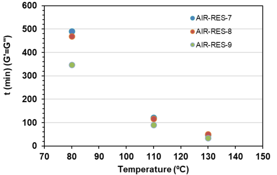
Viscosity and gel time as a function of temperature for the three formulations were measured to analyse their processability by RTM.
According to the results shown in Figure 1 and Figure 2, for all of them the viscosity profiles showed that the resins have a viscosity below 30 cps at 90°C, so this could be a good injection temperature to achieve adequate wetting of fibres. Moreover, at this temperature they have enough gel time to allow mould filling for the injection of large and complex geometry parts.
Furthermore, by increasing the temperature through higher mold temperature, e.g. 130°C, fast curing times can be achieved for improving production rates.
Summarizing, rheological characterization showed that the processing properties of the three formulations were suitable for RTM processes. Being very similar to the behaviour of AIR-RES-7 and AIR-RES-8, AIR-RES-9 shows lower viscosity but it is more reactive and therefore exothermic, which could be a drawback when injecting large pieces.
2.3.3 Dynamic properties
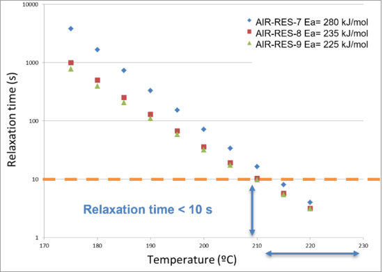
Due to the dynamic hardener, the three resin formulations were expected to show vitrimer behaviour. Their time and temperature dependent relaxation modulus were tested by DMA in order to characterize its heat induced malleability.
Based on the Maxwell’s model for viscoelastic fluids, relaxation times were determined as the time required to relax 63% of the initial stress [7]. The activaton energy of the bond exchange mechanisms Ea and temperature dependent relaxation modulus τ (s) were measured for each formulation.
The results in Figure 3 showed that at temperatures above Tg the 3R resins were able to completely relax stress and flow. It can be observed that AIR-RES-9 shows the lowest relaxation times on the whole temperature range, although above 210°C they are quite similar and lower than 10 s. On the other hand, higher activation energy Ea means higher thermal stability of the final composite material at temperatures below Tg. In this sense, AIR-RES-7 could be the best choice.
2.3.4 Mechanical properties
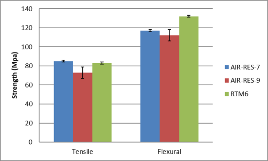
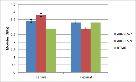
Mechanical characterization was performed on the two formulations with the most interesting dynamic properties, AIR-RES-7 and AIR-RES-9. Tensile and flexural properties of both resins were characterized at room temperature. The obtained results were compared with reference HexFlow® RTM6 resin, with which specimens were also manufactured and tested.
AIR-RES-7 formulation shows better performance than AIR-RES-9 and very similar to HexFlow® RTM6.
2.3.5 Discussion of results
The characterization results show some interesting differences among the three formulations studied, that are summarized in Table 3.
| AIR-RES-7 | AIR-RES-8 | AIR-RES-9 | |
| Tg | +++ | + | ++ |
| Rheology | Highest viscosity | Intermediate | Highest reactivity |
| Dynamism | Highest activation energy | Intermediate | Lowest relaxation times |
| Mechanical properties | ++ | + |
Based on the results, AIR-RES-7 was selected as the most promising formulation for thermoforming processing. To confirm the thermoforming capacity of this resin, a 2 mm thick resin plate fully cured was thermoformed in a mold with omega profile geometry, applying 0,5 bars at 200°C for 5 minutes. Figure 6 shows the result, confirming the reprocessability of the resin.
3 Development of laminates
3.1 Laminate production
The RTM manufacturing process is an out of autoclave process in which a dry preform, composed of several reinforcement layers stacked onto each other, will be impregnated with a liquid resin, and then cured. This process presents advantages in manufacturing cost and energetic consumption compared to an autoclave cycle. The RTM has been selected in this project to manufacture laminates that will be used as test panels for the material characterization, and in other work packages, they will be used as semi product for the development of 3R thermoforming process.
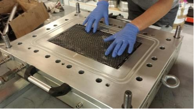
Eurecat has various RTM tools, the one commonly used for test panel manufacturing is the one presented below, as it allows to produce panels of 380x220mm with adjustable thickness from 2 to 5mm by using different “spacers”: intermediate parts between the mould and its cover. These spacers have injection and vacuum canals to adjust the injection strategy, the one here below has a central injection point on one side, and a vacuum line on the opposite, another strategy would be circumferential injection, from the centre of the cavity to edges.
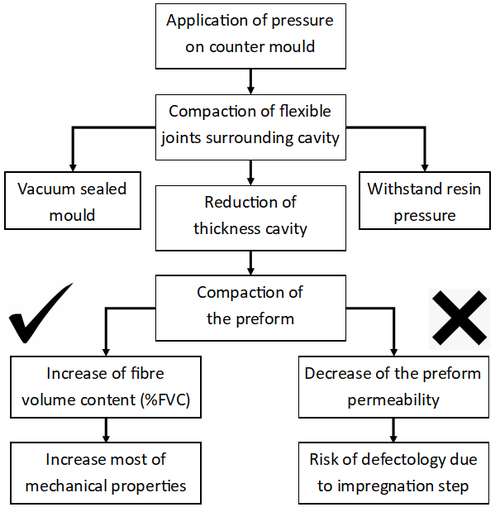
In most of the cases, the RTM requires a clamping of the top cover in order to close the mold and get it resin-tight, vacuum leak free, and to adjust the thickness and fiber volume content of the final cured part. In this case, considering the weight of 280g/m2 of the carbon fabric, 8 layers are laid in a 2mm thick mold cavity, in order to get a fiber volume content close to 58%.The diagram below shows the reason why an adequate clamping pressure is required on the cover:
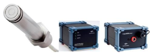
The presented RTM tool has an integrated in-mold DEA sensoring system which allows for an accurate control of the temperature, for resin arrival signal, and follow-up of its ionic viscosity.
The information collected by the sensor is useful in a production environment in order to detect any deviation from the standard curing cycle, but it is also of a great help when it is about opmitization and reduction of curing time.
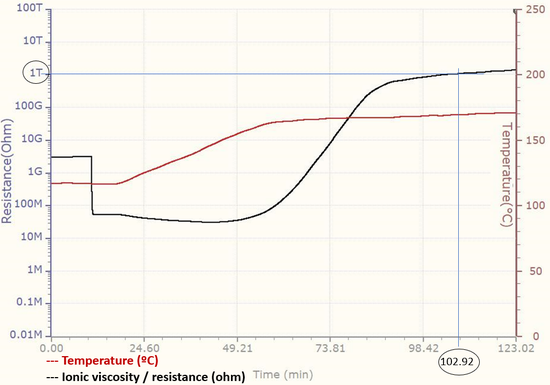
On an isotherm, the signal of ionic viscosity can be related with the degree of cure of the resin. Preliminar calibration of the sensoring system need to be done to assiociate different values of ionic viscosity with degree of cure or Tg obtained by DSC. On this example, at a constant temperature of 180ºC (red curve), the resistance, or ionic viscosity (black curve), is progressely increasing and overpass at t = 103mn the line of 1Tohm corresponding in this case to a minimum Tg of 165ºC.
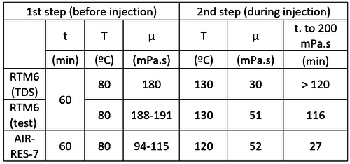
The 3R resin was formulated in order to conserve similar process window as comercial resin systems like the HexFlow® RTM6 from Hexcel. Particularly, this allow to inject at similar range of in-mould viscosity to make sure of the optimal impregnation of the dry preform. In this case, the viscosity of both resins at injection temperature is similar, around 50mPa.s.
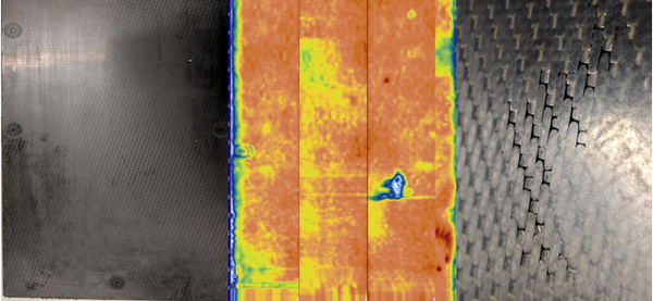
Before trimming the specimens, a NDT inspection was performed on the test panel to make sure it is free from any defect, such as of void or delamination. Thanks to the ultrasonic C-scan phased array equipment, cartography as the one presented below can detect dammage areas which will be discarded for the trimming of the specimens.
The coupons were then machined by high pressure waterjet cutting, setting parameters around 3.500 bars of pressure and 3.5 L/min of flowrate, avoiding the generation of any kind of defect while machining.
3.2 Laminate characterization
As previously detailed in this article, the 3R resin formulation AIR-RES-7 was selected and characterized, then composite test panels were manufactured by RTM to produce adequate specimens for mechanical testing. Once all the manufacturing parameters of the 3R laminates were set, a complete test campaign was designed and performed to compare the properties of the 3R material under development to commercial resin. For this purpose, the consortium of AIRPOXY built a data base of aerospace grade resin system properties mainly based on one of the most widely used in the aeronautical industry: the HexFlow® RTM6 from Hexcel.
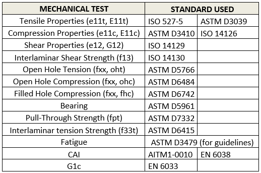
Specimens were tested at room temperature, but also after ageing in hot-wet conditions at temperatures of 80ºC and 120ºC. Two carbon reinforcements were characterized: the first was a unidirectional of IMS65 24K and 284g/m2 that was tested in both 0º and 90º directions, and the second was the 5-harness satin (5HS) of T800HB 6K and 280g/m2. Both fabrics included a polyamide veil of 8 g/m2 on one side to be able to preform the layers properly. All these 3R laminates were manufactured with the same process parameters and the same resin formulation: AIR-RES-7. Here below is the list of all the mechanical test performed during the project with the corresponding standard used for test parameters definition.
The results of tensile, compression and compression after impact (CAI) tests at room temperature for laminates produced with 5HS carbon fabric will be presented here.
Tensile testing is one of the most basic tests in composite materials, and the results is mostly depending on the fiber type. However, a bad result in this test may also be interpretated as bad interface, as the fiber can be pulled out from the matrix in such configuration.
Compression testing is more representative of the resin behavior compared to the tensile test. The compression modulus is generally defined by the fiber modulus, but the ultimate strength registered at failure is a representative information of resin toughness.
CAI testing is critical for an aerospace structure, and the test is more complex than the previous ones presented, as there are several steps involving numerous key parameters. In a first stage, the BVID (barely visible impact damage) needs to be correctly defined, in that case the objective was to get a 1mm dent, and a previous study set an impact energy of 27,5J to generate such dent. Once the test panels are impacted and inspected, the compression test could be done to measure the strength.
For each test a minimum of 5 specimens were prepared, however, some tests present higher variability than others due to the combined failure mode that can occur. This is especially the case of compression testing, for which it was decided to take the average values out of 10 tested specimens.
3.3 Test results
3.3.1 Mechanical characterization
In the table below, test results at room temperature are presented for laminates produced with the AIR-RES-7 formulation and 5HS carbon fabric reinforcement (57% of fibre volume content).
| Laminate | Properties | Unit | Result | Target |
| (0º)8 | Tensile strength |
MPa | 1060,2 | 980 |
| (0º)8 | Compression strength | MPa | 628,4 | 646 |
| (0/45/90/-45º)2S | Compression after impact (CAI) strength | MPa | 181,6 | 236 |
The results obtained for the tensile and compression tests were around the target. However, CAI test results were below expected, which could be due to the brittleness of the resin and/or incompatibility between the resin and the veil.
3.3.2 Validation of laminate thermoformability
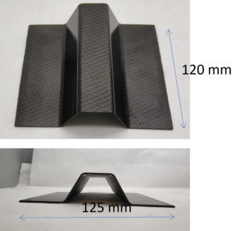
To validate the thermoforming capacity of the 3R composite, a 2 mm thick laminate produced with 5HS fabric and fully cured was thermoformed in a mould with omega profile geometry, applying 100 bars at 210°C for 5 minutes and subsequent cooling below Tg maintaining pressure.
A representative component after forming is shown in Figure 14.
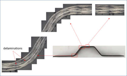
Thermoforming was successful, verifying that the component could be produced with a macroscopically good look. A closer microscopic analysis of three sections (Figure 15) showed a few delamination in the profile.
4 Conclusions and next steps
From the study carried out several conclusions were obtained:
- An aero grade epoxy resin, referenced as AIR-RES-7, was synthesized with the ability to be thermoformed due to its dynamic properties.
- Despite proving that the rheology of the resin allows the successful production of RTM panels, there is a margin for optimization of injection cycle.
- Reducing curing time using DEA a sensing system.
- Reducing heating temperature to decrease risk of exothermic reaction, and related energetic cost.
- First mechanical characterization of the panels showed good results for tensile and compression properties. Nevertheless CAI properties did not reach the target defined, which could be due to the brittleness of the resin and/or incompatibility between the resin and the polyamide veil on one side of the carbon fabric. Further investigations should be focused on the improvement of properties through two main routes:
- Development of tougher resin formulation
- Selection of a more suitable veil, e.g., lower areal weight and fiber diameter, lower melting temperature.
As the next steps in the project, in addition to the optimization of the 3R resin and the composite, various 3R manufacturing processes, bonding and repair technologies were developed that are currently being applied to produce two aerostructure demonstrators in an industrial environment.
Acknowledgements
This project has received funding from the European Union’s Horizon 2020 research and innovation program under grant agreement No 769274.
References
[() ] www.bbc.com/news/business-25833264
[2] www.iata.org/whatwedo/ops-infra/Pages/fuel-efficiency.aspx.
[3] Prof Dr. K Dreschler ( TUM), Prof Dr. P Middendorf ( Univ of Stuttgart), Dr A Erber ( SGL Group) – Carbon Composites : Material systems with improved mechanical behaviour for various industries – JEC COMPOSITES MAGAZINE – N°95 March 2015
[4] WO2015181054-A1
[5] Ruiz de Luzuriaga, A.; Martin, R.; Markaide, N.; Rekondo, A.; Cabañero, G.; Rodríguez, J.; Odriozola, I., Epoxy resin with exchangeable disulfide crosslinks to obtain reprocessable, repairable and recyclable fiber-reinforced thermoset composites. Materials Horizons 2016, 3 (3), 241-247.
[6] Ruiz de Luzuriaga, A.; Martin, R.; Markaide, N.; Rekondo, A.; Cabañero, G.; Rodríguez, J.; Odriozola, I., Correction: Epoxy resin with exchangeable disulfide crosslinks to obtain reprocessable, repairable and recyclable fiber-reinforced thermoset composites. Materials Horizons 2020, 7 (9), 2460-2461.
[7] L. H. Sperling, Introduction to Physical Polymer Science. John Wiley & Sons, New Jersey, USA, (2005).
Document information
Published on 30/10/22
Accepted on 30/10/22
Submitted on 30/10/22
Volume 06 - AEMAC en PROYECTOS EUROPEOS (2022), Issue Num. 2 - Monográfico Proyectos Europeos (2), 2022
DOI: 10.23967/r.matcomp.2022.11.03
Licence: Other
Share this document
Keywords
claim authorship
Are you one of the authors of this document?

