Abstract
This article discusses the design, operation, and performance evaluation of a unique cable-operated 6.24 kWp commercial-size solar tracking system called iPV dual-axis tracker or iPV DAT with a position detector to gain the maximum power from the sunlight. Compared with other solar tracking systems, low cost, simplified hardware structure, and controlling algorithm are the advantages of this system. The operating method of the 6.24 kWp iPV DAT follow a simple pull and release of the steel cables connecting the corners of the PV module frame to the electric motors and directed by an electronic control system. The steel cables attached to the corners of the module frame also provide an extra stability in the event of high wind of up to 220 km/h. The accuracy of the tracking effect is managed by an astronomical algorithm that enables a full 360° azimuth rotation and altitude tilt of −40° to 40° (0 = horizontal). The controller algorithm also includes backtracking capability that allows optimization of ground cover ratio. Performance evaluation of the iPV DAT installed and operated in Taiwan for 12 months is compared with a fixed-tilt PV system. An average electricity gain of 30.1% and performance ratio of 93% are realized using iPV DAT.
Introduction
Photovoltaic (PV) energy is fast becoming a major player in the worlds energy supply chain with about 177 GW deployed from 1992 to 2014 [1-4]. In 2014 alone, the worldwide PV installations in residential, commercial, and large scale utilities were 38.7 GW with most deployments in China (10.6 GW), US (9.76 GW), and Japan (6.2 GW) [1]. The continuous industrial growth, particularly in China and India, is considerably advancing the PV demand and supply trends. Although the efficiencies of PV modules have increased in the past years, there still exist limitations on how much energy output they produce in the field.
A wide range of mounting fixtures for PV modules are available such as building integrated PV systems (BIPV), including PV facades, sloped and flat roof mountings, integrated glass–glass modules and “PV roof tiles” or stand-alone fixed-tilt, and tracking systems. Single-axis and dual-axis tracking systems are becoming more attractive for PV utility systems, especially in countries with a high share of direct irradiation [3]. It is well known that a single-axis tracking system could generate up to 25% extra electricity compared to a fixed-tilt PV system, while a dual-axis tracking system can boost the electricity generation up to 45%, depending on the geographic location [3, 5-7]. It is also known that a single-axis tracker is cheaper than a dual-axis tracker; however, the high electricity yield from a dual-axis tracker makes it a favorable option. Currently, many companies offer products with different tracking possibilities varying from single-axis, dual-axis, single-vertical-axis, single-horizontal-axis, and single-tilted-axis [8-11]. Reviews of the benefits of sun-tracking systems have been discussed [6, 7, 12]. Despite the benefits of the dual-axis tracking system, there still remains some obstacles such as high cost, reliability, operation, and maintenance (O&M) requirements.
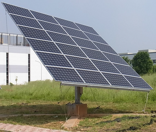
For the mass deployment of dual-axis tracker system into the market place, it needs to satisfy two main conditions – simple hardware structures that can guarantee stability and reliability against weather elements, and low capital and O&M costs. Conventional solar tracking systems use linear actuators, ball–screw or slew–wheel drive systems, which are complex and carry high capital and O&M costs resulting from oversized components. To address the cost issue, this article discusses a low-cost solar tracking system called intelligent dual-axis solar tracker (iPV dual-axis tracker or iPV DAT) that uses simple hardware structures and controller algorithm. The 6.24 kWp iPV DAT operations use a unique cable-drawn technology to direct the solar modules to the sun path for maximum electricity generation as shown in Figure 1. The key components of iPV DAT based on the cheapest available resource without compromise on the stability and reliability are discussed. In addition, the performance assessment of iPV DAT compared to a fixed-tilt PV system in Taiwan climatic conditions are also reported.
|
|
|
Figure 1. iPV DAT showing some of the key features in a test field. |
Design Configuration, Control, and Operation of iPV DAT
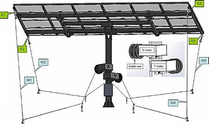
The key design features of iPV DAT include, main structural components, drive system, module mounting systems (rack and module clamps), electronic control unit, and foundations. An illustration of the iPV DAT with two electric motor (X and Y) and stainless steel cables (WI, W2, W3, and W4) connecting the motors to the module mounting frame is shown in Figure 2. The stainless steel cables linking the diagonal corners of the module frame (R1, R2, R3, and R4) are wound on cable reels in clockwise and anticlockwise directions in a W-shaped pattern. The main structures of the tracker are mostly constructed of galvanized steel (hot dip or zinc coated) with some stainless steel constituents such as the stainless steel cables. The galvanizations of the structural components are heavily coated to be able to withstand corrosion wear over a lifespan of at least 30 years.
|
|
|
Figure 2. An illustration of the iPV DAT showing some key design features (insert shows the details of the cable reels). |
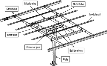
The iPV DAT module frame is designed to be able to rotate in two axes in the horizontal plane on a central pole. The pole is attached to the foundation platform with an anchor bolt. In addition, two anchors are placed on each arm of the foundation, one in the middle and the other on the end, and both provide dragging force to the pulley. The components of the overall tracker fixture are described in Figure 3. Table 1 shows a summary of the frame components and their functions. All of the iPV DAT components are prewelded (no welding required in the field). Welding in the field is time consuming and challenging to provide consistent results and installation time.
|
|
|
Figure 3. iPV DAT major frame components. |
| iPV DAT frame components | Functions |
|---|---|
| Foundation post | Supports the whole frame structure |
| Universal joint | A round tube connecting the foundation pole to the module frame at the middle section by a short axis fitted with ball bearings. The long end of the axis is primarily connected to the module mounting frame. These settings allow the module frame to rotate in two directions |
| Inner tubes | Rectangular tubes connect the universal joint to the outer tube via bearings |
| Middle tube | Rectangular tubes connect the inner tubes to the outer tubes and also help to reinforce the frame |
| Outer tube | Rectangular tubes which provide support to the module rail |
| Drive tube | Rectangular tubes that can be driven by stainless steel cable from the corners and provide support to the module rails |
| Module rail | T-shaped or L-shaped angle bars fixed on the outer tubes to support the PV modules |
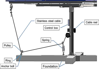
The iPV DAT drive system consists of two electric motors, shafts, ball bearings, cable reels, pulleys, shackles, anchoring bolts, springs, and stainless steel cables. Sections of the diagonal layout of the drive system are shown in Figure 4. The two motors are attached to the central pole and positioned in perpendicular direction. Each motor has a two-slot cable reel fitted on a rotation shaft. The stainless steel cables connecting the diagonal corners of the drive tube to the module frame are wound on the slot of the reel, one in clockwise direction and the other in anti-clockwise direction.
|
|
|
Figure 4. Sections of the diagonal layout of the iPV-DAT drive system. |
When the motor rotates the cable reel, one steel cable unwinds and the other winds up, thereby pulling the frame to rotate. The pulley connecting the anchor bolt diverts the horizontal or rotation force to vertical force so that less force is used to pull the module mounting frame downwards. The spring connecting the middle anchor bolts helps to modulate the tension of the stainless steel cable, so that it will not be too tight or too loose. Once the frame moves to the target position, all four steel cables will be tight, thus providing four anchoring forces for the mounting frame. This unique drive system maximizes the utilization of long torque arm by pulling the tracker frame from its corner and the steel cables can further anchor the whole frame. Through this simple drive system the azimuth and altitude angles can be controlled.
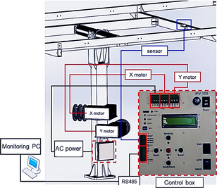
The control system consists of a programmable logic controller (PLC) that positions the iPV DAT throughout the day, depending on the calculated sun location. The controller is hard-wired to the two electric motors that wind or unwind the stainless steel cables as shown in Figure 5. The controller also reads input from the position sensor mounted on the tracker frame to confirm that the tracker is moved to the correct tilt angle and to avoid an over rotation of the tracker during the operation.
|
|
|
Figure 5. iPV DAT electronic controller system. |
The controller uses an astronomical algorithm based on the solar angle analyses, which moves the tracking surface into the calculated sun positions [13]. The inputs for the algorithm include the date and time of day, the latitude and longitude of the location, spacing between adjacent trackers in two directions (for multiple tracker installations), and real-time reading from the position sensor. Throughout the day, the PLC calculates the location of the sun to determine the optimum tilt angle for iPV DAT operation in normal or in backtracking mode. The module mount is moved every 5 min (travel time of 10 sec) to focus to the suns position, requiring less than 30 min of active motion per day and an annual power consumption of 14 kWh. The minimal motion time lowers the power consumption during iPV DAT operation, thus reducing the trackers wear and tear, and O&M costs. Backtracking mode helps to prevent the mutual shadowing from the adjacent trackers in a solar plant during sunrise and sunset. In this mode the surface angles of the trackers are moved away from the ideal values, just sufficient to keep the shadow outside the borderline of the adjacent trackers [14]. Other benefits of backtracking include maximum ground cover ratio and prevention of the harmful effects of hotspots due to shadowing [15-17]. The major benefits of the control system are described in Table 2.
| Features of the iPV DAT drive system | Benefits |
|---|---|
| Stainless steel cables drive system | The stainless steel cable drive is a unique feature that helps to steer the module mounting frame and also provides four anchor points |
| Spring | Helps to modulate the tension on the steel cables. Provides damping effects for the tracker in the event of gusty wind – to withstand wind of up to 120 km/h in operation mode and up to 220 km/h in safety (stow) position |
| Control system | The controller algorithm includes azimuth and altitude inputs, and backtracking capabilities which allow each tracker to follow the optimal sun path during operation in a solar plant |
Based on these drive and control systems, the iPV DAT have a tracking range from −40° to +40° from the horizontal plane. However, the tracking range can be widened using a taller post. The tracker can accommodate 60- or 72-cell modules. At sunset, the controller will return the iPV DAT to a horizontal position, which is also the wind stow position. At sunrise, the modules are reset to a tilt angle of −40° to begin its sun-tracking operation. Therefore, unlike some trackers that use solar irradiance measured by a photometer as a control signal, iPV DAT will rotate according to a predetermined solar trajectory based on an astronomical algorithm and has backtracking capacity during low irradiance hours. Table 3 shows the design specifications of the 6.24 kWp iPV DAT, which is the rated power at STC.
| Frame surface area | (21.7 × 20.3)ft. (6.6 × 6.2)m |
|---|---|
| Number of modules supported | 24 |
| PV capacity | 6.24 kWp |
| Annual electricity consumption | 14 (kWh/year) |
| Height (Excl. module) | 9.6 ft./2.9 m |
| Weight (Excl. module) | 1565 lbs./710 kg |
| Extreme Wind – Operational | 120 km/h |
| Extreme Wind – Safety Mode | 220 km/h |
The iPV DAT is designed to operate in an automatic tracking mode. The automatic operation of the system combines the capability for backtracking, returning to horizontal position at night, and wind stowing by means of a remote control system (remote computer). The tracker can also be manually controlled on site from the control box. The control system allows the tracker to automatically face the sun based on the calculated trajectory of the sun for any given time and location of the site. The control system sends data to the remote computer throughout the day in order to monitor the performance of the tracker.
Installation and Operation of iPV DAT and Fixed-Tilt PV Systems
The 6.24 kWp iPV DAT consisting of 24 PV modules and a 9.66 kWp fixed-tilt PV systems are installed in Taichung City, Taiwan with latitude 24.1500° N and longitude 120.6667° E°. The fixed-tilt PV system is installed on a flat roof-top with the modules mounted at an optimum tilt angle of 24° facing south. Both PV systems are situated at the same location. P-type monocrystalline PV modules with power ratings of 260 W are used in both PV systems. Both PV systems are grid-connected via DC/AC inverters. The iPV DAT is connected to a single DC/AC inverter, while the 9.66 kWp (rated power at STC) fixed-tilt PV system is connected to two DC/AC inverters. The rated maximum efficiency of the inverters is greater than 94%. The PV systems are operated for over a year and the performance data collected are analyzed and presented below. Apart from a periodic application of lubricant to the ball bearings, the iPV DAT required no major maintenance till date.
The measured daily, monthly, and yearly average irradiation, module temperature, inverter efficiency, performance ratio, and electricity generation are analyzed in order to compare the performance of the iPV DAT against that of the fixed-tilt PV system. As the installed power capacity of the iPV DAT is a little below the fixed-tilt PV system systems, the normalized electricity yield in kWh/kWp is used to compare their performances in a similar manner used by other researchers [18-21].
Performance Evaluations of the PV Systems
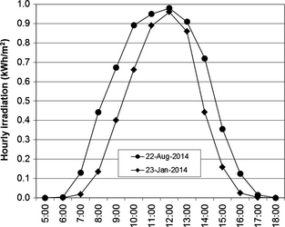
The global irradiation data for the iPV-DAT and fixed-tilt system over an operation time of 12 months (January to December, 2014) are measured at the installation site using radiation sensors mounted horizontally facing the sun. The radiation measurement sensor is attached to the array frame of the fixed-tilt PV system. The measured hourly global irradiation on a horizontal plane for a clear summer day of 22 August 2014 and a clear winter day of 23 January 2014 are shown in Figure 6. It is seen that the hourly irradiation for the summer day is more than that of the winter day due to the longer sunshine hours.
|
|
|
Figure 6. Hourly global solar irradiation measured for a clear summer and winter day. |
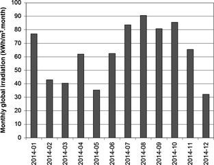
It is known that the irradiation level is location dependent and significantly affects the electricity yield of a PV system [22]. The summer and winter operating temperatures of the PV modules mounted on the iPV DAT and fixed-tilt PV systems are 52.5°C and 50.1°C, and 13.4°C and 12.8°C, respectively. The estimated average monthly horizontal irradiation measured is shown in Figure 7. The irradiation data compare very well with those obtained from the Taiwan Central Weather Bureau for Taichung City for the same period [23]. The cumulative irradiation is estimated to be 917 kWh/m2.
|
|
|
Figure 7. The estimated average monthly horizontal irradiation measured for the period of operation. |
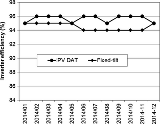
The iPV DAT and fixed-tilt PV system inverter efficiencies are shown in Figure 8. In general, the estimated annual average inverter efficiency is around 95%. It is interesting that even at low irradiation where the PV systems sometimes work at about 10% of their rated power, the inverter efficiency is still better than 94%.
|
|
|
Figure 8. The calculated inverter efficiencies for the iPV DAT and fixed-tilt PV system. |
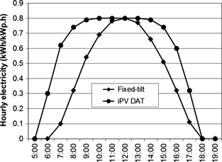
The hourly electricity outputs for the iPV DAT and fixed-tilt PV systems for a clear summer day of 22 August 2014 are shown in Figure 9. As expected, the hourly variation of the electricity output from the iPV DAT system is much larger than that of the fixed-tilt PV system. In the case of the iPV DAT, the electricity generation increases quickly and plateaued for some hours before dropping to lower values. This electricity output trend is similar to others that use complex and costly gearwheel/swivel and linear actuator drive systems [5]. The single-day electricity yield for the iPV DAT and fixed-tilt PV systems for 22 August 2014 are 8.1 kWh/kWp and 5.6 kWh/kWp, respectively, indicating a 44.6% electricity gain by the iPV DAT over the fixed-tilt PV system. In winter, the respective electricity generated by the iPV tracker and the fixed-tilt PV system on 23 January 2014 is 6.8 kWh/kWp and 4.9 kWh/kWp, amounting to a 38.8% electricity gain by the iPV DAT (plots not shown). These results show that a simple cable-drawn drive system of the iPV DAT can accurately steer the PV modules along the sun path to harvest a maximum amount of electricity throughout the day irrespective of the season, especially in the early morning and late afternoon. It is also noteworthy that during the peak time of day when electricity is taxed the most and power costs much more in the consumer marketplace than the average price, the iPV DAT can generate more electricity.
|
|
|
Figure 9. The hourly electricity outputs from the iPV DAT and fixed-tilt PV systems for a clear summer day of August 22, 2014. |
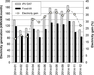
The monthly total electricity generated in kilowatt is shown in Figure 10. It is noticeable that for every month, the iPV DAT produces more electricity than the fixed-tilt PV system, particularly during the summer time. The highest electricity generated by the iPV DAT and fixed-tilt PV systems occurred during the month of October and the values are 186 kWh/kWp and 135 kWh/kWp, respectively. The lowest monthly electricity generation of 105 kWh/kWp and 84 kWh/kWp are recorded in the winter month of December 2014 by the iPV DAT and fixed-tilt PV system, respectively. The increased electricity yield observed in January also correlates with the high-measured solar radiation (Fig. 7). The cumulative annual electricity generated during the operation of iPV DAT and fixed-tilt PV systems are 1700 kWh/kWp and 1301 kWh/kWp, respectively. The total average electricity gain by the iPV DAT over the fixed-tilt PV system is 30.1%, while on monthly basis, higher electricity gains are achieved during the summer months as shown in Figure 10. The highest monthly energy gain of 38.2% is recorded in October 2014, while the lower electricity gain of 17.4% is obtained in January 2014.
|
|
|
Figure 10. The monthly total electricity generated per kWp for the iPV tracker and fixed-tilt PV system. |
From the measured data, it is apparent that the use of a simple cable-drawn iPV DAT in central Taiwan can lead to a significant electricity gain of 30.1% compared to the fixed PV system due to its sun-tracking effect. The electricity gain is known to depend on the geographical location [6], therefore, it is expected that a higher electricity gain can be attained in locations with higher latitude than Taiwan, with latitude of 24° N. In general the benefits of using the dual-axis tracker (including a simple and economical iPV DAT) for harvesting solar energy far exceeds the extra cost of the sun-tracking components compared to the fixed-tilt or single-axis tracking systems [24-26].
To further assess the performance of iPV DAT and fixed-tilt PV systems, the performance ratio (PR) are calculated. PR is an important parameter for evaluating the efficiency of a PV system [27, 28]. PR is the ratio of the actual and theoretically possible energy outputs from a PV system. Mathematically, it is represented as [29, 30];
|
|
(1) |
where Yf is the energy output divided by the nameplate DC power of the installed PV system, and Yr (reference yield) is the total in-plane irradiation divided by the PVs reference irradiation.
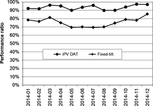
PR is independent of the orientation of a PV system and incident solar irradiation on the PV system, but it is mostly influenced by temperature, dirt and dust, mismatch and wiring losses, and DC to AC conversion losses [28, 31]. Hence, PR is used to evaluate different systems supplying the grid at the same or different locations in the world, since it takes into account the overall effect of losses on the PV systems rated output due to PV array temperature, unused irradiation, and system component inefficiencies or failures [28, 31]. The calculated monthly PR values for the iPV DAT and fixed-tilt PV systems are shown in Figure 11. The calculated average PR value for the iPV DAT and fixed-tilt PV system is 93% and 75%, respectively. The high PR value achieved for the iPV DAT may be due to the sun-tracking effect and integrity of the system design. The lower PR value exhibited by the fixed-tilt could be due to various loss factors emanating from the system. The monthly variations of the PR could be due to seasonal temperature changes and other loss factors. In general, PR of the iPV DAT system falls within the top rated values reported in the literature [28].
|
|
|
Figure 11. The calculated monthly PR values for the iPV dual-axis tracker and fixed-tilt PV system. |
Conclusion
The design, operation, and performance of a commercial-size iPV DAT that uses a unique steel cable-drawn drive system have been discussed. The control philosophy and operating mechanism of the iPV DAT follows a simple pull and release of the steel cables attached to the corners of the PV module mount via electric motors. The accuracy of the tracking effect is controlled by an electronic sundial that allows a full azimuth rotation of 360° and altitude tilt of −40° to +40° (0 = horizontal). The steel cables provide four anchor points and also act as stabilizing dampers to the PV array to combat high wind conditions of up to 220 km/h. Utilization of the backtracking method maximizes the ground cover ratio and enables more iPV DAT installations on a piece land without mutual shadowing or exposure of the PV modules to hot-spot risks. Performance evaluation of iPV DAT in Taiwan indicates that electricity gain of 30.1% can be achieved compare to fixed-tilt PV system. In general, the iPV DAT system can boost renewable generation based on a simple and cost effective cable-drawn drive system, thus reducing the carbon dioxide emission that causes climate change.
Conflict of Interest
None declared.
References
- Brunisholz, M. 2015. 2014 snapshot of global PV markets. Available at http://www.iea-pvps.org/fileadmin/dam/public/report/technical/PVPS_report_-_A_Snapshot_of_Global_PV_-_1992-2014.pdf (accessed 7 July 2015).
- Friedman, B., R. Margolis, and J. Seel. 2014. Comparing photovoltaic (PV) costs and deployment drivers in the Japanese and U.S. residential and commercial markets. Technical Report, NREL/TP-6A20-60360, Revised June, Available at http://www.nrel.gov/docs/fy14osti/60360.pdf (accessed 7 July, 2015).
- IEA PVPS. 2014. Report snapshot of global PV 1992–2013 preliminary trends information from the IEA PVPS programme, report IEA-PVPS T1-24:2014. Available at [=Report http://www.iea-pvps.org/index.php?id=trends0&no_cache=1&sword_list[]=Report] (accessed 7 July, 2015).
- TRENDS. 2013. IEA survey report of selected IEA countries between 1992 and 2012, Report IEA-PVPS T1-23:2013, Available at [=2013 http://www.iea-pvps.org/index.php?id=trends&no_cache=1&sword_list[]=2013]] (accessed 7 July, 2015).
- Eke, R., and A. Senturk. 2012. Performance comparison of a double-axis sun tracking versus fixed PV system. Sol. Energy86:2665–2672.
- Huld, T., M. Suri, and E. D. Dunlop. 2008. Comparison of potential solar electricity output from fixed-inclined and two-axis tracking photovoltaic modules in Europe. Pro. Photovoltaics16:47–59.
- Mousazadeh, H., A. Keyhani, A. Javadi, H. Mobli, K. Abrinia, and A. Sharifi. 2009. A review of principle and sun-tracking methods for maximizing solar systems output. Renew. Sustain. Energy Rev.13:1800–1818.
- Siemer, J.2009. An industry in transition. Global survey on tracking systems. Photon Int.11:138–189.
- Kimber, A., and L. Mitchell. 2005. Performance evaluation standards for large grid-connected PV systems in the United States and Germany. 20th European Photovoltaic Solar Energy Conference, Barcelona. 3229–3232.
- Baumgartner, F. P., A. Büchel, and R. Bartholet. 2008. Solar wings: a new lightweight PV tracking system. 23rd European Photovoltaic Solar Energy Conference, Valencia. 2790–2794.
- Garcıa, M., J. A. Vera, L. Marroyo, E. Lorenzo, and E. Pe'rez. 2009. Solar-tracking PV plants in Navarra: a 10 MW assessment. Prog. Photovoltaics Res. Appl.17:337–346.
- Gay, C. F, J. W. Yerkes, and J. H. Wilson. 1982. Performance advantages of two-axis tracking for large flat-plate photovoltaic energy systems. Proceedings of the 16th Photovoltaic Specialists Conference, San Diego. 1368–1371.
- Cucumo, M., D. Kaliakatsos, and V. Marinelli. 1997. General calculation methods for solar trajectories. Renew. Energy11:223–234.
- Perpiñána, O.2012. Cost of energy and mutual shadows in a two-axis tracking PV System. Renew. Energy43:331–342.
- Ineichen, P. 2011. Five satellite products deriving beam and global irradiance validation on data from 23 ground stations. Scientific report, University of Geneva, 2011. Available at http://www.cuepe.ch/html/biblio/detail_l.php?id=503&sr=&pr=&mjc=256 (accessed on 22 August 2014).
- Lorenz, E., T. Scheidsteger, J. Hurka, D. Heinemann, and C. Kurz. 2011. Regional PV power prediction for improved grid integration. Prog. Photovoltaics Res. Appl.19:757–771. doi: 10.1002/pip.1033.
- Friesen, G., S. Dittmann, S. Williams, R. Gottschalg, H. G. Beyer, de Guerin Montgareuil A., et al. 2009. Intercomparison of different energy prediction methods within the European project “Performance”—results on the 2nd round robin. 24th European Photovoltaic Solar Energy Conference and Exhibition, Hamburg, Germany. 3189–3197.
- Ransome, S. 2008. A review of kW h/kWp measurements, analysis and modelling. 23rd European Photovoltaic Solar Energy Conference, Valencia. 2795–2800.
- Koussa, M., A. Cheknane, S. Hadji, M. Haddadi, and S. Noureddine. 2011. Measured and modeled improvement in solar energy yield from flat plate photovoltaic systems utilizing different tracking systems and under a range of environmental conditions. Appl. Energy88:1756–1771.
- Kenny, R. P., E. D. Dunlop, H. A. Ossenbrink, and H. Mullejans. 2006. A practical method for the energy rating of c-Si photovoltaic modules based on standard tests. Pro. Photovol. Res. Appl.14:155–166.
- Kelly, N. A., and T. L. Gibson. 2009. Improved photovoltaic energy output for cloudy conditions with a solar tracking system. Sol. Energy83:2092–2102.
- Kelly, N. A., and T. L. Gibson. 2011. Increasing the solar photovoltaic energy capture on sunny and cloudy days. Sol. Energy85:111–125.
- Taiwan Central Weather Bureau (TCWB). 2014. Climate statistics, Monthly meteorological data. Available at http://www.cwb.gov.tw/V7/climate/monthlyData/mD.htm (accessed 18 November 2014).
- Oner, Y., E. Cetin, H. K. Ozturk, and A. Yilanci. 2009. Design of a new three degree of freedom spherical motor for photovoltaic-tracking systems. Renew. Energy34:2751–2756.
- Aldali, Y., and F. Ahwide. 2013. Evaluation of A 50MW two-axis tracking photovoltaic power plant for AL-Jagbob, Libya: energetic, economic, and environmental impact analysis. World Acad. Sci. Eng. Technol. Int. J. Environ. Ecol. Geol. Mining Eng.7:777–781.
- Perpinan, O., E. Lorenzo, M. A. Castro, and R. Eyras. 2009. Energy payback time of grid connected PV systems: comparison between tracking and fixed systems. Pro. Photovol. Res. Appl.17:137–147.
- IEC 61724. 1998. Photovoltaic system performance monitoring guidelines for measurement, data exchange and analysis. Edition 1.0, 1998-04.
- Reich, N. H., B. Mueller, A. Armbruster, W. G. J. H. M. van Sark, K. Kiefer, and C. Reise. 2012. Performance ratio revisited: is PR>90% realistic?Pro. Photovol. Res. Appl.20:717–726.
- Marion, B, J. Adelstein, K. Boyle, H. Hayden, B. Hammond, T. Fletcher, et al. 2005. Performance parameters for Grid-Connected PV Systems, 31st IEEE Photovoltaic Specialists Conference Orlando, Florida. January; 3–7.
- Woyte, A., M. Richter, D. Moser, S. Mau, N. Reich, and U. Jahn. 2013. Monitoring of Photovoltaic systems: Good Practices and systematic analysis, 28th European PV Solar Energy Conference and Exhibition, Paris, 30 September-4 October. 3686–3694.
- Axaopoulos, P. J., and E. D. Fylladitakis. 2013. Energy and economic comparative study of a tracking vs. a fixed photovoltaic system. Eur. Sci. J.9:1857–7881.
Document information
Published on 01/06/17
Submitted on 01/06/17
Licence: Other
Share this document
Keywords
claim authorship
Are you one of the authors of this document?
