Abstract
A hybrid machine (HM) is a system integrating two types of motor; servo and constant velocity with a mechanism. The purpose is to make use of the energy in the system efficiently with a flexible system having more than one degree of freedom (DOF). A review is included on hybrid press systems. This study is included as a part of an industrial project used for metal forming. The system given here includes a 7 link mechanism, one of link is driven by a constant velocity motor (CV) and the other is driven by a servo motor (SM). Kinematics analysis of the hybrid driven mechanism is presented here as inverse kinematics analysis. Motion design is very crucial step when using a hybrid machine. So motion design procedure is given with motion curve examples needed. Curve Fitting Toolbox (CFT) in Matlab® is offered as an auxiliary method which can be successfully applied. Motion characteristics are chosen by looking at requirements taken from metal forming industry. Results are then presented herein.
Keywords
Hybrid machine ; Inverse kinematics ; Motion design ; Press mechanism ; CF Toolbox
1. Introduction
Variable motion outputs can be obtained by two different ways in industrial applications. The first one is traditional machines and the other one is programmable machines. Hybrid machine idea is proposed to combine two techniques and to utilize from their good specifications and to remove their disadvantages. The basic principle of hybrid systems is to bring together the motion of a large CV motor with a small SM via a mechanical linkage mechanism. In these systems the constant velocity motor provides the main torque and motion requirements while the servo motor assists the modulations on the present motion. The CV motor undertakes a big amount of workload and the SM is like a real time regulator to change the task.
The first study is performed by Dülger (initially Tokuz) and Jones in hybrid configuration [1] . A constant velocity motor and a servo motor were integrated by a differential gearbox which further drives a slider crank mechanism [1] . Kireçci and Dülger have designed a hybrid manipulator with 3 DOF system; DC motor, gear unit, 2 DC SM, servo amplifier, motion control card, a slider crank mechanism and a screw mechanism [2] . Kireçci and Dülger have then offered a configuration of a planar two degree of freedom, seven link mechanisms by showing the reduction peak power requirement of servomotor was 3.5 times less than the peak power of CV motor [3] . Seth has performed a review work about programmable hybrid mechanisms [4] . Ouyang et al. have proposed a five bar linkage consists of a five bar linkage, an AC CV motor and a frequency controller, an AC brushless servo motor and a servo amplifier with a gear transmission, a shift encoder, a flywheel and a belt [5] . Yuan et al. have investigated two hybrid machines with a seven link, two DOF linkage mechanisms [6] . Zhang has proposed a hybrid five bar mechanism [7] . Connor et al. have presented a study on the synthesis of hybrid five bar path generating mechanisms using genetic algorithms [8] . Dulger et al. have presented a study on modeling and kinematic analysis of a hybrid actuator; a seven link mechanism with an adjustable crank [9] . Yu has offered a study with HM system using five bar mechanism [10] . Li et al. have studied on a hybrid driven mechanical press for precision drawing using a nine-bar linkage [11] . Li and Zhang have applied a seven bar linkage configuration with kinematics analysis and optimum design of hybrid system [12] . Du and Guo have studied on a metal forming press. Traditional configurations are studied, and a new hybrid configuration is proposed [13] . Meng et al. have then offered a new press mechanism. Link dimension optimization was performed. A significant reduction is obtained in the peak velocity and acceleration of the servo motor [14] . Li and Tso have presented a seven bar mechanism [15] . Tso and Li have later used a seven bar mechanism to investigate the stamping capacity and energy distribution between the servomotor and the flywheel with different motion inputs [16] . He et al. have studied on trajectory planning and optimization of a 25 tons industrial prototype with 2 DOF systems [17] . Tso has again used a seven bar mechanism. A control system with iterative learning control and feedback control techniques was developed [18] . Li et al. have proposed a novel hybrid driven mechanical press for deep drawing process [19] . Kütük has then studied on a hybrid driven two DOF systems with its inverse kinematics and motion design. Kütük has also considered all types of mechanisms especially used in press application. Motion requirements are given by press manufacturer here. A mathematical model concerning its power and energy use is not included in this study [20] .
In this study, different ram characteristics are aimed to try and see the availability of them on a hybrid machine. The scenarios used in metal forming industry are planned to be applied. At the end of the study, the flexibility of HM is proved with quick rise, slow return and dwelling periods. Due to the fact that it is an industrial project, the properties of the motion are directly taken from the company. The first thing to do is to design the motion. Segmentation technique is used due to each point of the motion cannot be represented by only a polynomial. The fifth order polynomials are preferred to identify the motion, because six inputs can be obtained from initial and final values of position, velocity and acceleration in each segment. Some ways are questioned how it can be employed more efficiently. Curve Fitting toolbox is tried for this purpose and it is seen that CFT is very profitable in estimating and then defining the initial and final quantities of the segments. This cooperation is firstly achieved in this study and shown on a case study. Inverse kinematics analysis of a hybrid machine has already been studied, but it is desired to exhibit particularly all details of derivations. It is believed that this study will answer the questions of the researchers being interested with HM systems and offer them a procedure about all these issues.
Other studies performed in the literature are tabulated according to actuator types, applications and mechanisms chosen are given in Table 1 .
| Name [reference] | DOF | Actuators | Application | Mechanism |
|---|---|---|---|---|
| Tokuz [1] | 2 | DC Motor & DC Servo | Press | Slider Crank |
| Dulger & Kireçci [2] | 3 | DC Motor & 2 DC Servo | Motion Modulation | Slider Crank & Screw |
| Kireçci & Dulger [3] | 2 | DC Motor & DC Servo | Motion Modulation | Seven Bar |
| Ouyang et al. [5] | 2 | AC Motor & AC Servo | Press | Five Bar |
| Yuan et al. [6] | 2 | DC Motor & DC Servo | Press | Seven Bar |
| Zhang [7] | 2 | DC Motor & DC Servo | Point to point positioning | Five Bar & Screw |
| Dulger et al. [9] | 2 | DC Motor & DC Servo | Modulation for textile industry | Seven Bar |
| Li et al. [11] | 2 | DC Motor & DC Servo | Precision Drawing | Nine Bar |
| Li & Zhang [12] | 2 | DC Motor & DC Servo | Deep Drawing | Seven Bar |
| Du & Guo [13] | 2 | DC Motor & DC Servo | Metal forming (Dwell) | Seven Bar |
| Meng et al. [14] | 2 | DC Motor & DC Servo | Press | Seven Bar |
| Li & Tso [15] | 2 | AC Motor & AC Servo | Press | Seven Bar |
| Tso &Li [16] | 2 | AC Motor & AC Servo | Press | Seven Bar |
| He et al. [17] | 2 | DC Motor & DC Servo | Forging | Seven Bar |
| Li et al. [19] | 2 | DC Motor & DC Servo | Deep Drawing | Seven Bar |
A hybrid machine system is studied with inverse kinematics. A motion design procedure is performed by revising motion requirements from metal forming applications. Motion profiles are designed, and studied with required kinematics. Final decision is made by manufacturers in this field. The paper is organized as follows. Section 1 gives background on hybrid systems. Section 2 presents the motion design. 3 and 4 show the inverse kinematics analysis for the mechanism and synthesis issues. Section 5 ends with the inverse solution curves for hybrid driven sense. Section 6 presents the main contributions of this study.
2. Motion design
The trajectories are considered with continuous position, velocity and acceleration. Initial and final conditions are given for them. Six boundary conditions are available to be used for a fifth degree polynomial [21] . The motion design is composed of obtaining the position, velocity and acceleration of the slider link. The slider displacement, velocity and acceleration are expressed in fifth order polynomials as;
|
|
( 1) |
|
|
( 2) |
|
|
( 3) |
where a, b, c, d, e and f refer the coefficients of the polynomial and t denotes time.
They can be expressed in matrix form
|
|
( 4) |
|
|
where pi , vi and ai are the initial displacement, velocity and acceleration, pf , vf and af are the final displacement, velocity and acceleration of the slider link, ti and tf are the initial and final values of the motion time, respectively. The coefficients of the fifth order polynomial are found as
|
|
( 5) |
Number of segments and the points where the segments are separated from each other are directly related with the designed motion and choice of the designer [20] and [21] .
2.1. Motion examples
Two motion curve examples are presented here to date different application characteristics. They are called as Motion 1 and Motion 2. To improve the accuracy and quality of forming products, especially in deep drawing operations, different control points are applied. This certainly reduces cracks, winks, and even if spring-backs with higher productivity.
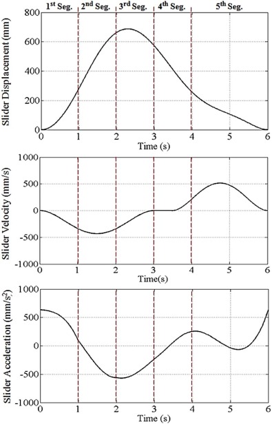
- Motion 1: Slider motion is a quick rise and slow return motion. Stroke of the slider is 687 mm and stroke per minute is 10. The displacement, velocity and acceleration of the slider are shown in Fig. 1 . Motion 1 is comprised by five segments. The main specifications of each motion segment are given in Table 2 . The segment number, time interval, initial and final values of position, velocity and acceleration of each segment are necessary to form the motion.
|
|
|
Fig. 1. Kinematics characteristics – Motion 1.
|
| Segment number | Time interval (s) | Position (mm) | Velocity (mm/s) | Acceleration (mm/s2 ) | Coefficients of the B vector | |||||
|---|---|---|---|---|---|---|---|---|---|---|
| a | b | c | d | e | f | |||||
| 1 | 0 ≤ t ≤ 1 | 0, 281.4 | 0, 479.8 | 635.3, 94.11 | 0 | 0.318 | 318.16 | −10.33 | 5.15 | 20.91 |
| 2 | 1 ≤ t ≤ 2 | 281.4, 662.7 | 479.8, 166.6 | 94.11, −558 | 35.41 | 97.26 | 194.85 | 128.34 | 125.77 | 22.18 |
| 3 | 2 ≤ t ≤ 3 | 662.7, 570.22 | 166.6, −293.3 | −558, −233 | 869.97 | 2105.23 | 2417.25 | 1033.26 | 187.33 | 12.40 |
| 4 | 3 ≤ t ≤ 4 | 570.22, 255.4 | −293.3, −248.5 | −233, 252.75 | 5861.19 | 9262.93 | 6463.07 | 2155.88 | 339.44 | 20.39 |
| 5 | 4 ≤ t ≤ 6 | 255.44, 0 | −248.5, 0 | 252.75, 635.3 | 40,038.48 | 47,474.7 | 21,629.97 | 4809.11 | 525.23 | 22.60 |
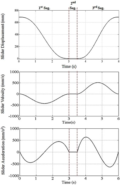
- Motion 2: Slider motion is a slow return-dwell and quick rise motion. Stroke of the slider is 687 mm and stroke per minute (SPM) is accepted as 10. The displacement, velocity and acceleration curves of the slider are shown in Fig. 2 . Motion 2 includes three segments. The kinematics specifications of each segment are given in Table 3 .
|
|
|
Fig. 2. Kinematics characteristics – Motion 2.
|
| Segment number | Time interval (s) | Position (mm) | Velocity (mm/s) | Acceleration (mm/s2 ) | Coefficients of the B vector | |||||
|---|---|---|---|---|---|---|---|---|---|---|
| a | b | c | d | e | f | |||||
| 1 | 0 ≤ t ≤ 3 | 687, 0 | 0, 0 | 0, 0 | 687 | 0.0134 | 13.391 | 267.826 | 131.682 | 17.458 |
| 2 | 3 ≤ t ≤ 3.5 | 0, 0 | 0, 0 | 0, 0 | 0 | 0 | 0 | 0 | 0 | 0 |
| 3 | 3.5 ≤ t ≤ 6 | 0, 687 | 0, 0 | 0, 0 | 80,608.07 | 93,071.46 | 42,103.75 | 9303.62 | 1002.47 | 42.20 |
2.2. Application in curve fitting toolbox
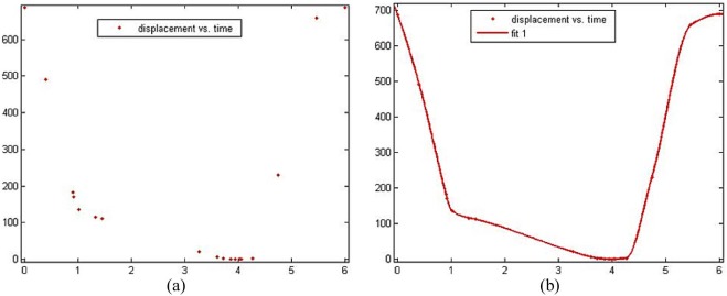
Curve Fitting Toolbox in Matlab© is used as a tool in this study to design the motion characteristics of the slider. The Curve Fitting Toolbox is not directly used in motion design operation. Having given the via points desired, Curve Fitting Toolbox is then run. An example is given to clarify the procedure here. A data set is given in x and y direction. This data set includes eighteen numerical values. The data in x and y direction are loaded, and formed in Fig. 3a . The type of fit is selected next. The shape preserving technique is chosen from the interpolant option of type of fit in Fig. 3b .
|
|
|
Fig. 3. Data in CF Toolbox and fitted curve (CF Toolbox).
|
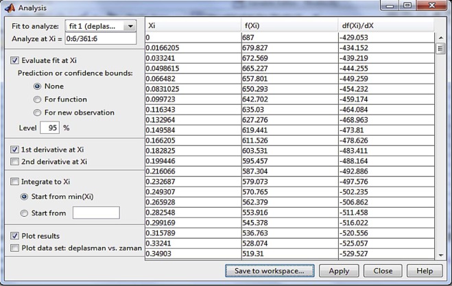
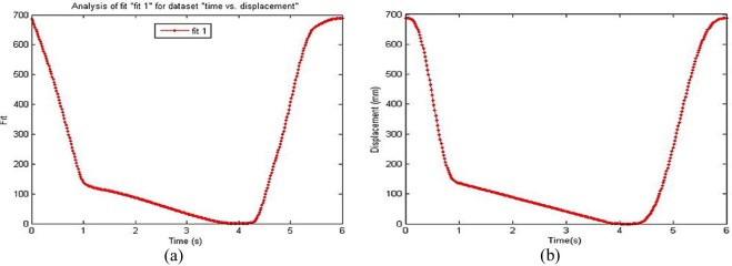
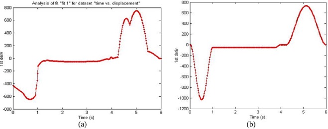
In Curve Fitting Toolbox, it is feasible to obtain more numerical value from a fitted curve. If only 18 values are available, the user can get more numerical value by using Analysis option of the Curve Fitting Toolbox. It is shown in Fig. 4 that the curve formed only eighteen datas is transformed into a curve formed by three hundred and sixty one numerical datas. The displacement curve with 361 datas is given in Fig. 5a . Differentiation in first and second order or integration of the curve is possible in Analysis option. The first order differentiation gives the results of motion velocity in Fig. 6a . Some undesired points are available. It is inevitable that this discontinuities in velocity characteristics can cause undesirable peaks in acceleration and jerk characteristics. The aim is to eliminate discontinuties on condition that the main characteristics of the motion is provided. With the availability of the selected new via points, the motion is formed again by using Eqs. (1) , (2) , (3) , (4) and (5) . The revised displacement and velocity characteristics of the motion are given in Fig. 5 and Fig. 6 , respectively [22] . At the end of this operation, while there is not a significant difference between fitted and revised displacement curves, a great improvement is visible between fitted and revised velocity curves.
|
|
|
Fig. 4. Analysis option (CF Toolbox).
|
|
|
|
Fig. 5. Curve with 361 data – revised motion displacement.
|
|
|
|
Fig. 6. Velocity of fitted curve – revised motion velocity.
|
3. Inverse kinematics analysis – hybrid driven mechanism
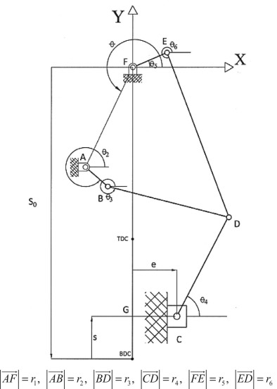
A hybrid driven mechanical system is presented in Fig. 7 . The system is composed of a planar five bar mechanism ABDEF and a dyad of CD. All joints except one are revolute joints. The exception is a prismatic joint used in translational motion between the slider and ground. The lengths of the links are represented by r1 , r2 , r3 , r4 , r5 and r6 as shown in Fig. 7 . The crank r5 is driven by a constant velocity motor. The crank r2 is driven by a servo motor. The link r1 is the ground link and is the orientation angle of it. The coordinate axes are fixed at point F. The BDC is the Bottom Dead Center point of the slider in which r4 , r5 and r6 are lined up in a straight line. The starting point of the slider is assumed as BDC, and top dead center of the slider is TDC point. In this mechanism, while EF link is driven by a constant velocity motor, AB link is driven by a servo motor.
|
|
|
Fig. 7. Schematic representation of hybrid driven mechanical system.
|
Here, the equations of inverse kinematics are derived and forward kinematics equations are obtained. By using the sketch of the mechanism in Fig. 7 , two loop closure Eqs. [23] are written as below. Loop 1 and Loop 2 are given as:
|
|
( 6) |
|
|
( 7) |
These two equations can be written in Euler form [24] .
|
|
( 8) |
When the Eqs. (6) and (7) are written in Euler form, and separated into two parts, Loop 1 and Loop 2 can then be written as below;
|
|
( 9a) |
|
|
( 9b) |
|
|
( 10a) |
|
|
( 10b) |
XA and YA are horizontal and vertical positions of point A, respectively. XA and YA can be written as follows;
|
|
( 11) |
s is the displacement function of the slider required by different motion characteristics. S0 is the point where r5 , r6 and r4 are lined up in a straight line and calculated as follows;
|
|
( 12) |
3.1. Position analysis
From the equations of Loop 1 and Loop 2, the angular displacement of the crank r2 can be obtained in terms of the rotation angle and the slider displacement s.
|
|
( 13) |
Loop 1 equations are transformed into the following form;
|
|
( 14) |
|
|
( 15) |
is eliminated by taking the squares of these two equations and adding to each other. The following equation is resulted [14] .
|
|
( 16) |
where
|
|
( 17a) |
|
|
( 17b) |
|
|
( 17c) |
Taking , , . Eq. (18) can be obtained.
|
|
( 18) |
|
|
( 19) |
From Eq. (9b)
|
|
( 20) |
Loop 2 equations are transformed into the following equations;
|
|
( 21a) |
|
|
( 21b) |
is eliminated by taking the squares of these two equations and adding to each other, the following equation is resulted.
|
|
( 22) |
where
|
|
( 23a) |
|
|
( 23b) |
|
|
( 23c) |
Similarly, is then derived by using Eq. (22)
|
|
( 24) |
The angular displacement of the third link can be found from Eq. (10b) ;
|
|
( 25) |
The angular velocities of each link of the mechanism are given in Appendix A2 . The angular acceleration of each link of hybrid driven mechanical system is included in Appendix A3 .
4. Linkage synthesis of hybrid driven mechanism
Different motion characteristics of the slider are satisfied as, the input link r2 and r5 must make complete rotations. Li [25] has given classifications of hybrid five-bar linkages by using the unrestraint double-crank type. The input link r2 and r5 are unrestraint cranks. The inequality constraints are defined as follows:
|
|
( 26a) |
|
|
( 26b) |
|
|
( 26c) |
The following inequality constraints should be satisfied to provide slider mobility condition.
|
|
( 27) |
Here XD represents the coordinate of point D in x direction. In order to have appropriate link lengths, the link lengths inequality constraints are given as follows:
|
|
( 28) |
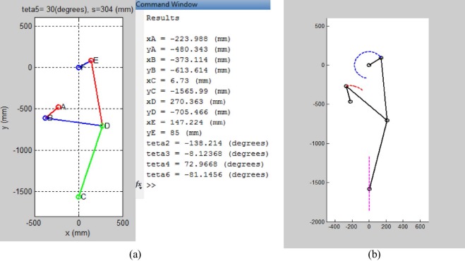
The link dimensions of the hybrid driven mechanism are found and tabulated in Table 4 . All dimensions are given in mm and the orientation angle, , is in degrees. Now it is possible to see the simultaneous position of the mechanism by applying inverse kinematics procedure in Fig. 8a . With the availability of the angular displacement data of constant velocity motor and servo motor, an animation on hybrid driven mechanism motion is created in Fig. 8b .
|
|
|
|
|
|
e |
| |||||||||||||||||||||
|---|---|---|---|---|---|---|---|---|---|---|---|---|---|---|---|---|---|---|---|---|---|---|---|---|---|---|---|---|
| 530 | 200 | 650 | 900 | 170 | 800 | 6 | 245 |
|
|
|
Fig. 8. Simultaneous position – animation of the hybrid mechanism.
|
5. Required motion inputs–outputs
The main objective of this part is to obtain the kinematics specifications of the second link driven by the servo motor shown in Fig. 7[19] . Inverse kinematics equations are used to realize this purpose.
5.1. Solutions for Motion 1 and Motion II
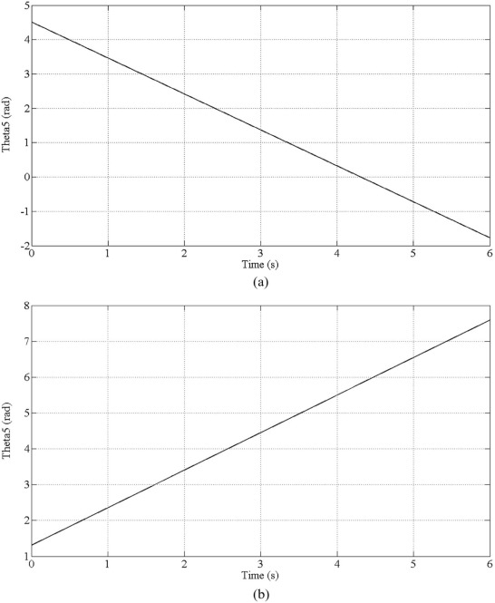
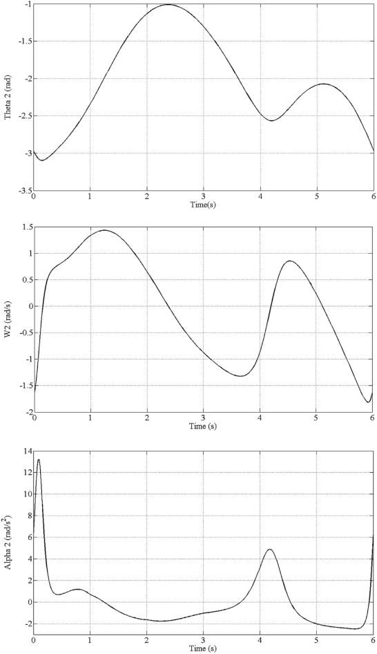
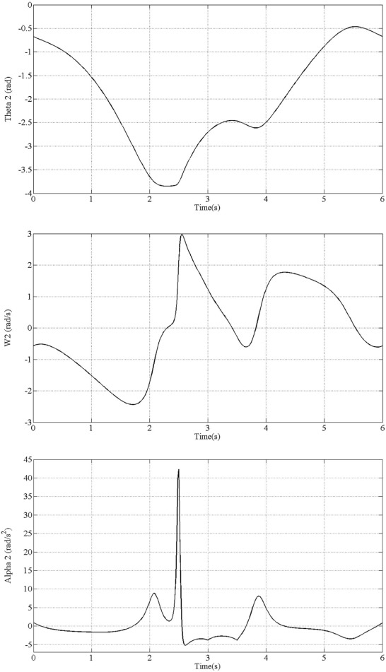
The first designed slider motion is given in Fig. 1 . The fifth link driven by a constant velocity motor will rotate 2 * π radians in CW direction with an angular velocity of −1.0472 rad/s. Angular displacement of the fifth link are shown in Fig. 9a . The angular displacement, velocity and acceleration of the second link are shown in Fig. 10 . The second designed slider motion is given in Fig. 2 . The fifth link rotates 2 * pi radians in (CCW) with an angular velocity of 1.0472 rad/s. Angular displacement of the fifth link is shown in Fig. 9(b) . By utilizing the inverse kinematics equations, the angular displacement, velocity and acceleration of the second link are obtained in Fig. 11 .
|
|
|
Fig. 9. Angular displacement of the CVM for Motion1 and Motion 2.
|
|
|
|
Fig. 10. Kinematics of SM (Motion1).
|
|
|
|
Fig. 11. Kinematics of SM (Motion 2).
|
6. Conclusions
The main contributions of this study can be listed as below.
In this study, it is proved that different motion scenarios can be achieved by hybrid machine system. Not only quick rise, slow return and vice versa, but also dwell motion which is definitely necessary for metal forming process has been tried and it is showed that flexibility has been supplied in a hybrid manner with the use of servo motor.
- A two degree of freedom planar mechanism driven by a constant velocity motor and a servo motor is presented in this study. It is composed of seven links with seven revolute joints and one prismatic joint. In this study, the basic methodology for deriving inverse kinematics equations has been obtained step by step with all details. It is applied in order to get the kinematics specifications of the servo motor. In this technique, kinematics properties of the crank driven by constant velocity motor and slider link are used as input parameters of the system. Inverse kinematics analysis is vital to analyze HM system. In this operation, it is not always possible to get an integer number for angular displacement of the crank driven by servo motor. Starting point of angle of the crank driven by the constant velocity motor is playing an important role. Because, there is a trajectory to be followed by the ram. It is a stroke. During the time which it takes, the crank driven by constant velocity motor is completing a full rotation. However, the tip point of the crank driven by the servo motor has a working envelope. If it is violated, the angular displacement values for servo motor will not be feasible. They may become complex numbers. It means that the ram trajectory to be traced is not provided. Then it must be modified after all. It is a very important issue that must be taken into account by the designers.
- Two different motion characteristics are designed. Motion design issues have been investigated on the existing hybrid studies. Any detailed study including design procedure has not been seen yet. This study has a significance to be a guide for that purpose. The motions designed and the mechanism selected in this study are suitable for metal forming industry like deep drawing and forging operations. Therefore, some limitations are occurring. Moving the ram from TDC to BDC in a very short time is really hard to achieve. Because the motion of the ram is more dependent to CV motor than SM. SM is only like a regulator to make the system more flexible.
- The motion is divided into segments by considering its complexity and the fifth order polynomials were used to characterize them. Curve Fitting technique is very useful in motion design as an auxiliary tool. In segmentation technique proposed, the starting and final quantities of position, velocity and acceleration of each segment must be defined accurately in order to get smooth characteristics. But these values are very hard to predict. According to clues obtained by CFT, the via points can easily be defined to frustrate the peak points in velocity and acceleration profile. Segmentation and CFT are used in order to complement each other. The applicability is shown on an example.
- Studies on the experimental part are still going on the hybrid issue especially on system verification and mathematical modeling with actuator dynamics.
Acknowledgements
The authors would like to thank the Ministry of Science, Industry and Technology for financial support under SANTEZ project. (No: 01422.STZ.2012-I ).
Appendix A1. Derivatives of loop equations
By differentiating Eqs. (9a , 9b ) and (10a , 10b ) with respect to time, the following equations are found;
|
|
( A1.1a) |
|
|
( A1.1b) |
|
|
( A1.1c) |
|
|
( A1.1d) |
By differentiating Eqs. ((A1.1a) , (A1.1b) , (A1.1c) and (A1.1d) ) with respect to time and rearranging them, Eqs. ((A1.2a) , (A1.2b) , (A1.2c) and (A1.2d) ) are obtained;
|
|
( A1.2a) |
|
|
( A1.2b) |
|
|
( A1.2c) |
|
|
( A1.2d) |
where r1 , r2 , r3 , r4 , r5 , r6 , θ and e are the dimensional parameters of the hybrid driven mechanism (Fig. 7 ).
Appendix A2. Angular velocities of the links
|
|
( A2.1a) |
|
|
( A2.1b) |
|
|
( A2.1c) |
|
|
( A2.1d) |
Appendix A3. Angular accelerations of the links
|
|
( A3.1a) |
|
|
( A3.1b) |
|
|
( A3.1c) |
|
|
( A3.1d) |
According to Eqs. (A2.1a , A2.1b , A2.1c , A2.1d ) and (A3.1a , A3.1b , A3.1c , A3.1d ), the angular velocity and of the crank driven by servo motor can also be written.
|
|
|
|
References
- [1] L.C. Tokuz; Hybrid machine modelling and control; Ph.D. thesis; Liverpool Polytechnic (1992)
- [2] L.C. Dülger, A. Kireçci; Hibrid Manipülatörün Modellenmesi ve Simülasyonu, 7. Ulusal Makine Teorisi Sempozyumu; YTU, Istanbul (1995), pp. 311–320
- [3] L.C. Dülger, A. Kireçci; A study on a hybrid actuator; Mech. Mach. Theory, 35 (1999), pp. 1141–1149
- [4] B. Seth; Programmable hybrid mechanisms; Proceedings of the 11th World Congress in Mechanism and Machine Science (2004) Tianjin, China
- [5] P.R. Ouyang, Q. Li, W.J. Zhang; Design, modelling and control of a hybrid machine system; Mechatronics, 14 (2004), pp. 1197–1217
- [6] Z. Yuan, M.J. Gilmartin, S.S. Douglas; Design of hybrid machines for nonuniform motion production; Proc. Inst. Mech. Eng. C, 219 (2005), pp. 491–499
- [7] K. Zhang; Optimization dynamics design of hybrid driving mechanisms; Proceedings of the 2006 IEEE International Conference on Mechatronics and Automation, IEEE, Luoyang, Henan, China (2006), pp. 1914–1919
- [8] A.M. Connor, S.S. Douglas, M.J. Gilmartin; The synthesis of hybrid five bar path generating mechanisms using genetic algorithms; Genetic Algorithms in Engineering Systems: Innovations and Applications, IET, Sheffield (1995), pp. 313–316 No: 414
- [9] L.C. Dülger, A. Kireçci, M. Topalbekiroglu; Modeling and simulation of a hybrid actuator; Mech. Mach. Theory, 38 (2003), pp. 395–407
- [10] H. Yu; Modelling and control of hybrid machine systems, a five-bar mechanism case; Int. J. Autom. Comput, 3 (2006), pp. 235–243
- [11] H. Li, Y. Zhang, H. Zheng; Dynamics modeling and simulation of a new nine-bar press with hybrid driven mechanism; J. Mech. Sci. Technol, 22 (2008), pp. 2436–2444
- [12] H. Li, Y. Zhang; Seven bar mechanical press with hybrid driven mechanism for deep drawing; part 1: kinematics analysis and optimum design, part 2: dynamic modeling and simulation; J. Mech. Sci. Technol, 24 (11) (2010), pp. 2153–2160 2161–2167
- [13] R. Du, W.Z. Guo; The design of a new metal forming press with controllable mechanism; Trans. ASME, 125 (2003), pp. 582–591
- [14] C.F. Meng, C. Zhang, Y.H. Lu, Z.G. Shen; Optimal design and control of a novel press with an extra motor; Mech. Mach. Theory, 39 (2004), pp. 811–818
- [15] C.H. Li, P.L. Tso; Experimental study on a hybrid driven press using iterative learning control; Int. J. Mach. Tools Manuf, 48 (2008), pp. 209–219
- [16] P.L. Tso, C.H. Li; Study of servo press with a flywheel; J. Adv. Mech. Des. Syst. Manuf, 2 (1) (2008), pp. 1–11
- [17] K. He, Y. Luo, C.T. Kong, R. Du; Trajectory planning, optimization and control of a hybrid mechanical press; WSEAS Trans. Syst, 8 (2009), pp. 614–627
- [18] P.L. Tso; Optimal design of a hybrid-driven servo press and experimental verification; J. Mech. Des. N. Y., 132 (2010), p. 034503
- [19] H. Li, L. Fu, Y. Zhang; Optimum design of a hybrid-driven mechanical press based on inverse kinematics; J. Mech. Eng, 56 (2010), pp. 301–306
- [20] M.E. Kütük; Hybrid machine systems: analysis and control; M.Sc. thesis; University of Gaziantep (2013)
- [21] L. Biagiotti, C. Melchiorri; Trajectory Planning for Automatic Machines and Robots; Springer (2008)
- [22] MathWorks; Curve Fitting Toolbox Use with Matlab© Users Guide; The MathWorks Inc. (2002)
- [23] E. Soylemez; Mechanisms; M.E.T.U Mechanical Engineering Department, Ankara (1999) Publication Number: 64
- [24] N.R. Norton; Design of Machinery: An Introduction to the Synthesis and Analysis of Mechanisms and Machines; (third ed.)McGraw Hill Companies (2004)
- [25] H. Li, C. Zhang, C. Meng; A hybrid-driven nine-bar press for precision drawing; Proceedings of the 11th World Congress in Mechanism and Machine Science (2004), pp. 1141–1145 Tianjin, China
Document information
Published on 10/04/17
Licence: Other
Share this document
Keywords
claim authorship
Are you one of the authors of this document?

