Abstract
In modern, stressed distribution system, voltage stability is a major concern from planning and operation perspectives. Remote wind farm connected to a weak distribution system through a long line could adversely affect the voltage stability of the respective distribution network. This paper investigates the transient and steady-state voltage issues of a distribution network with a distant doubly fed induction generator (DFIG)-based wind farm. Results show that a distant DFIG-based wind farm could improve the voltage stability of a distribution network with a large motor load in steady-state operating condition as well as following disturbances, like three-phase faults, sudden load tripping, and motor starting.
Introduction
In countries like Australia large mining loads, agro farms, etc., are generally located far from distribution load center, maybe near the area of wind power potential. When a wind farm is integrated at the end of a distribution feeder with such large motor loads and existing residential customers, steady-state and transient voltage stability of the respective power network are affected. The impact of the wind farm on the voltage stability of a distribution system needs to be studied to identify its effects on the existing networks and customers.
Voltage instability occurs due to the inability of a power system to maintain acceptable voltages at all buses under normal conditions and during disturbances [1]. Especially large induction motors, as a form of distribution load, can consume a significant amount of reactive power upon network disturbances, negatively influencing fault recovery [2] by pushing distribution system voltage to particularly low levels.
Variable speed wind turbine with doubly fed induction generators (DFIGs) is one of the most frequently used wind turbine generator technologies. In contrast to common induction generators, DFIG are equipped with a rotary field excitation system, which allows supporting the stator excitation, exclusively done by the network in common induction machines. In addition, this allows controlling the rotor speed by setting a specific excitation field frequency. This allows maintaining turbine rotor speed at a more favorable speed extracting more energy compared to squirrel cage induction generator [3]. In addition, a DFIG-based wind farm operating at lagging power factor control mode provides reactive power support during network disturbances and can contribute to system voltage stability.
Several researchers have studied voltage stability issues in distribution systems with wind farms. Jakus et al. [4] have presented a methodology for calculating annual voltage profile and slow voltage variations of a distribution system with wind integration. The study indicates an improvement of voltage profile with the wind integration. According to [5] the voltage stability of a power system during small and large disturbances can be improved with the wind integration, especially when combined with reactive power compensation. Mariltto et al. [6] and Linh [7] have presented methods for finding steady-state voltage stability region for each distribution buses with wind power generation. Both the papers have determined the maximum permissible load in each bus within the voltage limit allowed by the utilities. Paper [8] has studied the voltage stability and grid loss-related issues of a distribution system with DFIG-based wind farm for heavy unbalanced loading conditions. The study shows that multiple small-DFIG system could provide higher system voltage improvement but similar grid loss reduction in comparison to single large-DFIG system. Sarkhanloo et al. [9] have presented a control strategy for a small wind farm with fixed and variable speed wind turbines to minimize voltage fluctuation and to improve transient stability of the wind farm. With this strategy variable speed wind turbines using DFIG support-fixed speed wind turbines using IG with reactive power during disturbances and hence improve the stability. Reference [10] has presented a reactive power margin-based volt ampere reactive (VAR) planning for improving dynamic voltage stability of a distribution system with IG-based wind farm. Authors have shown this can reduce power losses and improve the voltage regulation of the distribution system. According to [11] the fixed speed wind technology using squirrel cage induction generator (SCIG) requires large reactive power support from the network but the variable speed wind technology using DFIG could improve distribution voltage stability without additional reactive power compensation device. Dicorato et al. [12] have observed that variable speed wind technologies like inverter-coupled permanent magnet synchronous generator (PMSG) and DFIG are able to restore voltage and power following a grid fault with quicker restoration in DFIG-based wind farm.
Especially the effect a remote wind farm has on the voltage stability of a weak distribution system requires special attention. Thus, this paper investigates the voltage stability effects of a DFIG-based wind farm when connected near a large motor load at the end of a distribution feeder in steady-state condition and following system disturbances like system faults, sudden motor tripping, and motor starting. The paper contributes to the understanding of how a DFIG-based wind farm effects on overall voltage stability of a distribution system when connected near a large motor load on a remote end of a distribution feeder.
The remainder of the paper is organized into five sections. Test distribution system gives description of the studied test system and the modification on the system made for this study. Modeling of doubly fed induction generator discusses the modeling of DFIG-based wind farms. Steady-state voltage stability analysis assesses the steady-state voltage stability of the modeled distribution system with and without the wind farm. The transient simulation results obtained from both study cases are presented and compared in transient voltage stability analysis. The paper concludes with a summary and discussion of results in conclusions.
Test Distribution System
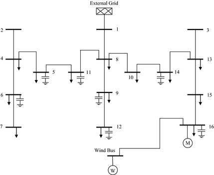
A modified 16-bus, 23 kV, 100 MVA distribution system [13] as in Appendix A has been used in this study. The distribution system is connected to a 23 kV, 50 Hz external grid through bus 1. In this study, the influence of wind farm into the distribution system stability is of concern so the system loads (total of 28.7 MW and 17.3 MVAr) are modeled as constant impedance load to achieve simplicity in analysis. For the study presented in this paper, the test system has been modified with three induction motors been added to bus 16, with power of 1 MW per motor as a base case for this study. The additional motor load is added at the bus 16 to simulate a remotely located large industrial/commercial load-like mining company, agro-farm, etc., which is normally located far from distribution load center. At the base case, the system voltages are very low, with 0.9123 pu at bus 16 and 0.9149 pu at bus 15.
Six DFIG-based wind turbines, each with 1.5 MW (total 9 MW), operated at power factor control mode are connected to the bus 16 through a 15 km cable. The wind farm is connected to the same bus as the motors so as to observe the effect of the wind farm on the large industrial load at the end of the distribution network. The studied test system is simulated with DIgSILENT PowerFactory 15.0.
Modeling of Doubly Fed Induction Generator
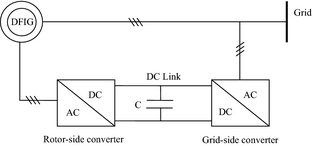
DFIG is a wound rotor induction generator connected to the wind turbine rotor through a gearbox. The stator is connected to the balanced three-phase grid and rotor power is fed to the grid through a back to back pulse width modulation voltage source inverter with a common DC link. The power converter decouples grid frequency with the mechanical rotor frequency enabling variable speed wind turbine generation [14]. The control system generates pitch angle command signal for rotor-side converter and voltage command signal for grid-side converter to control wind turbine power, DC voltage, and the reactive power. Figure 1 shows the schematic diagram of DFIG.
|
|
|
Figure 1. Schematic diagram of doubly fed induction generator. |
The mechanical power extracted from the wind is given as [15];
|
|
(1) |
where ρ is the air density (m3), r is the radius of the turbine (m), v is the wind speed (m/sec), CP (λ) is the power coefficient, and λ is the tip speed ratio.
d-q axis stator and rotor flux are given by [16];
|
|
(2) |
where ids and iqs are d- and q-axis stator currents; idr and iqs are d- and q-axis rotor currents; Ls, Lr, and Lm are stator inductance, rotor inductance, and magnetizing inductance, respectively. d-q axis stator and rotor voltages are given by [16]:
|
|
(3) |
where uds and iqs are d- and q-axis stator voltages; udr and udr are d- and q-axis rotor voltages; Rs and Rr are stator and rotor resistances; ωs is synchronous speed and ωsl is slip frequency.
Steady-State Voltage Stability Analysis
Steady-state (small signal) voltage stability is the ability of a power system to maintain voltages under normal condition and following small perturbations like gradual change in loads [1]. In a weak distribution system, voltage instability may be initiated by lack of reactive power support and system characteristics. Bus voltage analysis and P-V characteristic are studied with and without remote DFIG-based wind farm to observe the effect of the wind farm in the steady-state voltage stability of a weak distribution system.
Bus voltages analysis
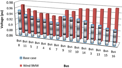
The bus voltages are observed for distribution network at the base case and with the integration of the modeled wind farm. The increase in bus voltages is an indicator of distribution system moving away from voltage instability point for steady-state operation, whereas decrease in bus voltages indicates toward steady-state voltage instability. Figure 2 shows that the voltages at all buses are improved after inclusion of the wind power. The voltage of bus 15 is improved from 0.9149 pu at base case to 0.9746 pu with wind power penetration. Similarly the voltage of bus 7 is improved from 0.9178 pu at base case to 0.9343 with the wind penetration. It is observed that the buses near the wind farm showed better voltage improvement compared to the remote buses. It is worth noting that the wind farm is operated at power factor control mode (0.95 lagging).
|
|
|
Figure 2. Bus voltages at base case and with 9 MW wind farm connected. |
The overall voltage improvement of the distribution system with the wind power penetration is an indication for enhancement in the steady-state voltage stability of the power network, which is further observed and verified in active power-voltage (P-V) characteristics analysis.
Active power-voltage (P-V) characteristics analysis
Voltage instability is a localized problem but can have widespread impact. This situation is governed by the relationship between transmitted active power, injected reactive power, and receiving end voltage. This relationship holds important role in voltage stability and can be represented graphically with P-V curve [1, 17]. At the knee point of the P-V curve, the voltage rapidly drops with an increase in load demand and power flow solution fails to converge indicating voltage instability [1]. Static voltage stability P-V analysis technique is used to assess the voltage stability of the studied distribution network.
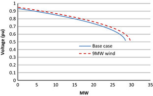
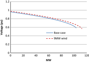
Figure 3 shows that maximum loading margin of bus 6 is increased from 28.41 MW at base case to 29.46 MW under the presence of the wind farm. As presented in Figure 4, similar improvement in loading margin is observed for bus 8. Bus 8 shows an increment from 103.41 to 112.42 MW from base case to wind power integration. This suggests wind farm can contribute to enhance maximum loading margin of the distribution buses which are even far from the point of connection of wind farm.
|
|
|
Figure 3. P-V curves of bus 6 for base case and with 9 MW wind farm. |
|
|
|
Figure 4. P-V curves for bus 8 for base case and with 9 MW wind farm. |
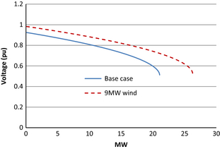
In Figure 5 P-V characteristic is plotted for bus 15 to observe the effect of wind farm on a bus close to the point of connection. It is worth noting, that the distribution buses near the point of connection of wind farm shows higher improvement in maximum loading margin. As can be observed from Figure 5 bus 15 shows improvement from 21.06 MW at base case to 26.26 MW with the wind being connected.
|
|
|
Figure 5. P-V curves for bus 15 for base case and with 9 MW wind farm. |
From the P-V analysis, it can be observed that bus near the wind farm has higher increment in maximum loading margin compared to those far from the wind farm. Hence these studies show that DFIG-based wind farm can contribute to increase the maximum loading margin of distribution system buses increasing the steady-state voltage stability.
Transient Voltage Stability Analysis
Transient voltage stability is the ability of a distribution system to control voltages following large disturbances like faults, sudden loss of load, and generation [1]. For the analysis of transient voltage stability, time domain simulation is conducted following a system disturbance, and voltage and power flows oscillations are observed. The different cases studied on this test system are:
- 10-cycle, three-phase faults at different buses.
- Sudden loss of motor load.
- Motor starting.
10-cycle three-phase faults
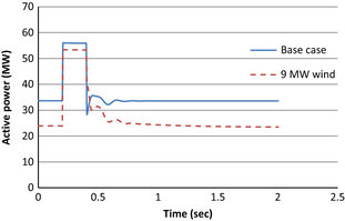
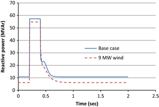
A three-phase 10-cycle zero impedance fault was initiated at t = 0.2 sec on bus 15 and the fault is cleared at 0.4 sec. The voltage and power transients are plotted for both the studied cases.
The active power drawn from the external grid for three-phase fault at bus 15 is plotted in Figure 6. During the fault the wind integrated distribution system draws 55.94 MW compared to 53.35 MW in base case. The transient response after the fault clearing is also better damped with the wind integration.
|
|
|
Figure 6. Active power drawn from external grid for a three-phase fault at bus 15 for base case and with 9 MW wind farm. |
Similarly during the fault, the wind integrated distribution system draws 54.77 MVAr compared to 57.32 MVAr in base case as seen in Figure 7. The reduction in reactive power requirement from the external grid shows that the DFIG can provide reactive support during the fault. It is further observed that the reactive power is better damped in case of wind integration.
|
|
|
Figure 7. Reactive power drawn from external grid for a three-phase fault at bus 15 for base case and with 9 MW wind farm. |
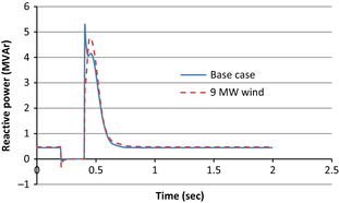
Figure 8 shows the reactive power drawn by one unit (1 MW) of the motor loads for base case and with 9 MW wind farm. The reactive power demand of the motor following the three-phase fault has shown over shoot up to 5.25 MVAr in base case but with the wind farm the reactive power demand is reduced and peaked at 4.76 MVAr.
|
|
|
Figure 8. Reactive power drawn by one motor (1 MW) for a three-phase fault at bus 15 for base case and with 9 MW wind farm. |
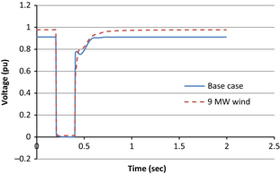
The voltage at bus 16 shows improvement for three-phase fault with the wind farm being connected to the distribution system compared to the base case as shown in Figure 9 and the voltage transient following a fault clearance is better damped with the wind farm.
|
|
|
Figure 9. Voltage at bus 16 at base case and with 9 MW wind farm for a three-phase fault at bus 15. |
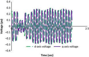
The d-axis and q-axis rotor voltages of DFIG-based wind farm for three-phase fault at bus 15 are plotted in Figure 10. The wind farm shows voltage recovery after the fault clearance as observed in the rotor voltage oscillations.
|
|
|
Figure 10. d-axis and q-axis rotor voltage of a 1.5 MW DFIG unit in the wind farm following a three-phase fault at bus 15. |
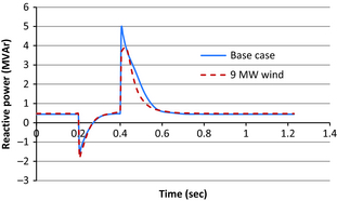
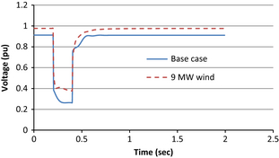
Next, the voltage stability study is performed to study the response of the wind farm for a distant fault. For this a three-phase fault is simulated at bus 5 and the reactive power demand of a motor load (1 MW motor unit) and bus voltage 16 are observed. Figures 11, 12 show the reactive power drawn by 1 MW motor and the voltage of bus 16. The DFIG-based wind farm integrated distribution system shows improved voltage stability compared to the base case.
|
|
|
Figure 11. Reactive power drawn by one motor (1 MW) for a three-phase fault at bus 5 for base case and with 9 MW wind farm. |
|
|
|
Figure 12. Voltage at bus 16 for base case and with 9 MW wind farm for a three-phase fault at bus 5. |
Sudden loss of motor load
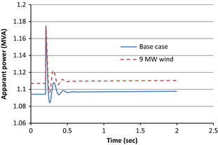
The simulation is conducted to observe the impact of sudden loss of one motor (1 MW motor load) on the stability of the distribution system. Out of three motors (each 1 MW with total of 3 MW) at bus 16, 1 MW motor unit is suddenly tripped at 0.2 sec and apparent power oscillation is observed for 2nd motor unit. In Figure 13, it is observed that the power oscillation with DFIG- based wind farm integrated distribution system shows less oscillation compared to base case.
|
|
|
Figure 13. Power fluctuation in one 1 MW motor at base case and with wind farm for tripping of another 1 MW motor. |
Motor starting
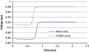
To observe the effect of motor starting on the voltage stability of the distribution system, one motor out of 3 motors at bus 16 is started with remaining two running. The condition with 2 motors running and starting 3rd motor is considered as the worst case for starting motor load (with the assumption that only one is started at a time). With wind integrated system the voltage at bus 16 is dropped down to 0.910 pu, whereas at the base case the bus voltage drops down to 0.855 pu as shown in Figure 14. This study shows that the wind farm could help to maintain voltage of a weak voltage bus within acceptable voltage range during motor starting.
|
|
|
Figure 14. Voltage dip at the motor terminal (bus 16) for base case and with 9 MW wind farm during motor starting. |
Conclusions
The steady-state and transient voltage stability of a distribution system with and without a remote DFIG-based wind farm is analyzed in this paper. The wind farm is operated in power factor control mode of 0.95 lagging to support reactive power as well.
Bus voltage analysis shows improvement in system bus voltages at all the buses of the distribution system with the wind integration. The buses in the proximity of the wind farm show higher increment in the bus voltages. P-V characteristics analysis shows that the maximum loading margin of all the buses is enhanced with the wind farm. Hence the study shows that a distant DFIG-based wind farm in power factor controlled mode with reactive power support can improve the steady-state voltage of a weak distribution system.
Transient voltage stability analysis for three-phase fault, sudden loss of motor load, and motor starting show that the wind farm can contribute to improve the voltages and power oscillations during and following the studied transient conditions.
In this study, it is observed that a remote DFIG-based wind farm can be connected to a weak distribution system without losing the voltage stability.
Conflict of Interest
None declared.
Appendix A
|
|
Modification in test system:
- Motor load: 1 MW, pf 0.9 Induction motor (3 units total 3 MW) Rr = 0.0199 pu, Xr = 0.189 pu, Rs = 0 pu, Xs = 0.01 pu; Rm = 0.019 pu; Xm = 2.91 pu.
- DFIG Wind Farm: 1.5 MW (6 units total 9 MW) Rr = 0.0563 pu; Xr = 0.0312 pu; Rs = 0 pu; Xs = 0.1 pu; Rm = 0.056 pu; Xm = 3.64 pu.
- Bus 11 is connected to bus 8: Line 8–11 → R(pu) = 0.11; X(pu) = 0.11;
- Line 16-Wind_Bus: 15 km of 23 kV cable R = 0.098 Ω/km; X = 0.114 Ω/km; C = 0.302 μF/km.
References
- Kundur, P.1994. Power system stability and control. McGraw Hill, New York, NY.
- Aziz, T., T. K. Saha, and N. Mithulananthan. 2011. Static and dynamic VAR planning to support widespread penetration of distributed generation in distribution system. Pp. 1–6in21st Australasian Universities Power Engineering Conference (AUPEC), Brisbane, Australia, 25–28 September 2011.
- Elkington, K., V. Knazkins, and M. Ghandhari. 2007. Pp. 213–218inOn the rotor angle stability of power systems with doubly fed induction generators. Power Tech IEEE, Lausanne Stockholm, Sweden.
- Jakus, D., R. Goic, and J. Krstulovic. 2011. The impact of wind power plants on slow voltage variations in distribution networks. Electr. Pow. Syst. Res.81:589–598.
- Lahacani, N. A., D. Aouzellag, and B. Mendil. 2010. Static compensator for maintaining voltage stability of wind farm integration to a distribution network. Renew. Energy35:2476–2482.
- Mariotto, L., H. Pinheiro, G. Cardoso, and M. R. Muraro. 2007. Determination of the static voltage stability region of distribution systems with the presence of wind power generation. Pp. 556–562inInternational Conference on Clean Electrical Power, Capri, 21–23 May 2007.
- Linh, N. T. 2009. Voltage stability analysis of grids connected wind generators. Pp. 2657–2660 in 4th IEEE Conference on Industrial Electronics and Applications, Xi'an, 25-27 May 2009.
- Dong, B., S. Asgarpoor, and W. Qiao. 2009. Voltage analysis of distribution systems with DFIG wind turbines. Pp. 1–5inIEEE Power Electronics and Machines in Wind Applications, Lincoln, NE, 24–26 June 2009.
- Sarkhanloo, M. S., A. S. Yazdankhan, and R. Kazemzadeh. 2012. A new control strategy for small wind farm with capabilities of supplying required reactive power and transient stability improvement. Renew. Energy44:32–39.
- Roy, N. K., H. R. Pota, and M. J. Hossain. 2013. Reactive power management of distribution networks with wind generation for improving voltage stability. Renew. Energy58:85–94.
- Zheng, C., and M. Kezunovic. 2010. Distribution system voltage stability analysis with wind farms integration. PP. 1–6inNorth American Power Symposium, Arlington, TX, 26–28 September 2010.
- Dicorato, M., G. Forte, and M. Trovato. 2012. Wind farm stability analysis in the presence of variable-speed generators. Energy39:40–47.
- Dahal, S., N. Mithulananthan, and T. Saha. 2010. Investigation of small signal stability of a renewable energy based electricity distribution system. Pp. 1–8inIEEE Power and Energy Society General Meeting, Minneapolis, MN, 25–29 July 2010.
- Fernandez, L. M., F. Jurado, and J. R. Saenz. 2008. Aggregated dynamic model for wind farms with doubly fed induction generator wind turbines. Renew. Energy33:129–140.
- Fernandez, R. D., R. J. Mantz, and P. E. Battaiotto. 2007. Impact of wind farms on a power system, an eigenvalue analysis approach. Renew. Energy32:1676–1688.
- Bian, X., C. T. Tse, C. Y. Chung, and K. W. Wang. 2010. Dynamic modeling of large scale power system with FACTS and DFIG type wind turbine. Pp. 753–758in2nd IEEE International Symposium on Power Electronics for Distributed Generation Systems. Hefei, China 16–18 June 2010.
- Aziz, T., S. Dahal, N. Mithulananthan, and T. K. Saha. 2010. Impact of widespread penetrations of renewable generation on distribution system stability. Pp. 338–341in6th International Conference on Electrical and Computer Engineering, Dhaka, Bangladesh, 18–20 December 2010.
Document information
Published on 01/06/17
Submitted on 01/06/17
Licence: Other
Share this document
Keywords
claim authorship
Are you one of the authors of this document?
