Abstract
Earth air heat exchanger (EAHE) systems are insufficient to meet the thermal comfort requirements in winter conditions. The low heating potential of such systems can be improved by integrating the system with solar air heating duct (SAHD). The aim of this paper is to present a model to estimate the heating potential for EAHE system with and without SAHD. The model is generated using TRNSYS 17 simulation tool and validated against experimental investigation on an experimental set-up in Ajmer, India. The experiment was done during the winter season, where the system was evaluated for different inlet flow velocities, length and depth of buried pipe. From the experimentation, it was observed that the depth of 3.7 m is sufficient for pipe burial and the 34 m length of pipe is sufficient to get optimum EAHE outlet temperature. It is also observed that increase in flow velocity results in drop in EAHE outlet temperature, while room temperature is found to increase for higher velocities (5 m/s). The COP of the system also increased up to 6.304 when assisted with solar air heating duct. The results obtained from the experiment data are in good agreement with simulated results within the variation of up to 7.9%.
Keywords
Earth air heat exchanger ; Solar air heating duct ; Parametric analysis ; Air flow velocity ; TRNSYS
Abbreviations
DBT , dry bulb temperature of air (°C) ; EAHE , earth air heat exchanger ; PVC , poly vinyl chloride ; RPM , revolution per minute ; SAHD , solar air heating duct
1. Introduction
The energy consumption of building for cooling and heating purpose has increased over the couple of years. Especially in colder countries, conventional heating systems cause huge peak load demand, which may be reduced by use of passive heating systems. Such systems are known for their benefit of consuming almost negligible energy as compared to conventional cooling and heating systems [1] and [2] . An earth air heat exchanger (EAHE) is one of the passive cooling and heating systems, having benefits of reduced energy consumption and CO2 emission. According to ASHRAE, below an approximate depth of 3 m the soil temperature remains constant throughout the year and is in close range with mean annual ambient air temperature [3] . The soil can, therefore, be used as a heat source in winter. As ambient air travels through the EAHE, it receives heat from surrounding soil, resulting in higher outlet temperature of EAHE as compared to the ambient. The outlet air from EAHE may be used directly for space heating if it is at sufficient temperature, else it may be heated further by either passing through conventional air conditioning system or through solar air heating duct. Such use of EAHE can contribute to reduction in energy consumption and carbon emission.
Various research work has been done using the ground as a heat source. Bansal et al. developed a model to predict the effect of operating parameters (air velocity, pipe material) on the heating capacity of earth air pipe heat exchanger systems using the FLUENT simulation tool [4] . Al-Ajmi et al. [5] studied the cooling capacity of EAHE for domestic buildings in a desert climate. Wu et al. [6] studied the effects of the functioning parameters (i.e. air flow rate, pipe radius, length, and depth) on the cooling ability of EAHE systems using CFD modeling. Mihalakakou et al. [7] , by using single and multiple parallel pipe EAHE, investigated the impact of ground surface boundary conditions for system efficiency. They observed improved cooling performance of grass-covered ground surface over bared soil condition. Mihalakakou et al. [8] developed a parametric (velocity of air, pipe radius and length,) model based on multi-correlation to calculate the thermal performance of EAHE exchanger.
The performance of three EAHE for mid-European office buildings was investigated by Pfafferott [9] for characterizing their efficiency using four different approaches. For ground-coupled heat pump application, Cui et al. [10] presented a finite element numerical model to simulate EAHE for varying operation modes over a short time period. Santamouris et al. [11] presented a novel balance point temperature-based integrated method to calculate the function of EAHE to reduce the cooling load of buildings. They concluded that this method can be used in the design of EAHE for dimensioning of buried pipes. Ghosal et al. [12] examined the thermal performance of ground air collector and EAHE for space heating of greenhouse. Their results showed that the temperature of greenhouse air with the ground air collector was 2–3 °C higher as compared to EAHE and concluded that ground air collector was more effective for the same length of buried pipe. Sodha et al. [13] investigated an EAHE system for heating/cooling to provide air conditioning inside the hospital building complex in India. Their results showed that an 80 m long tunnel had a 269 kWh heating capacity, which was not adequate for providing the necessary comfort conditions. Jakhar et al. [14] evaluated the performance of the EATHE with SAHD for winter heating. They concluded that the COP of system increased up to 4.57 when coupled with SAHD. Badescu [15] developed a model to predict the effect of the ground heat exchanger on energy delivered and found its heavy dependency on design parameters like material, pipes depth and diameter. Cooling and heating energy of the system was reduced by increasing the pipe diameter. Kumar et al. [16] examined the conservation potential of an EAHE system integrated with a building. The cooling potential for the earth pipe was evaluated as 19 kW for pipe length of 80 m, with air flow velocity of 4.9 m/s and section area of 0.53 m2 .
From the above discussion, it is clear that there exists a gap to estimate the parametric assessment of solar air heating duct (SAHD) coupled with EAHE system. The objective of the present study is to model the transient investigation of thermal performance for such system during winter season and validate it experimentally. The parametric model has been developed in TRNSYS 17 simulation tool by taking EAHE with and without SAHD. During the experimentation, the effects of inlet flow velocity of air, length and depth of buried pipe on the performance of the system were studied by operating it for 8 hours daily during winter season.
2. Description of the TRNSYS simulation
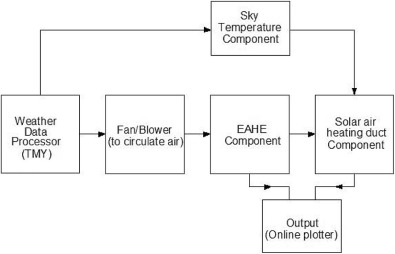
TRNSYS, a transient simulation system tool, models the renewable energy systems to estimate the transient variation [17] . Using this tool numerical simulation of the EAHE with SAHD was carried out by using its inbuilt Meteonorm files for weather conditions. The model design includes inbuilt system components which take parameters and time-dependent inputs of desired system and produces a time-dependent outputs. Various components, which are designated as Type, can be interconnected with a flow chart. In the current system the models for EAHE and SADH were used to estimate the transient output over a period of time. A simplified information flow diagram for the EAHE with SAHD system under investigation is shown in Fig. 1 .
|
|
|
Fig. 1. TRNSYS information flow diagram for the EAHE with SAHD.
|
As shown in the Fig. 1 , the component for the fan (Type 3) is connected to EAHE (Type 952), which is further connected to SAHD (Type 607). Weather component (Type 15) when connected to sky temperature component (Type 575) provides the scenario of EAHE with SAHD. The simulations were performed for both cases, i.e., EAHE with and without SAHD component (further discussed in Section 4 ). Here a given output of one component is used as an INPUT to a number of other components. For the simulation, the physical and thermal parameters of the system taken are shown in Table 1 .
| Material | Density (kg m−3 ) | Specific heat capacity (kJ kg−1 K−1 ) | Thermal conductivity (W m−1 K−1 ) |
|---|---|---|---|
| PVC | 1380 | 0.900 | 0.160 |
| Air | 1.225 | 1.006 | 0.024 |
| Soil | 2050 | 1.840 | 0.521 |
3. Experimental set-up and instrumentation
Ajmer has a hot semi-arid climate with annual average ambient temperature of 26.7 °C. The climate of Ajmer is representative of a composite climate, and winters (November to February) are chilly with lower temperature of about 5 °C. During winter, the weather remains mild and temperate with average temperatures ranging from 15–18 °C. The absolute minimum and mean minimum temperature of ambient air is close to 4 °C and 9 °C, respectively, in the winter.
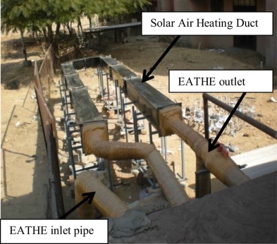
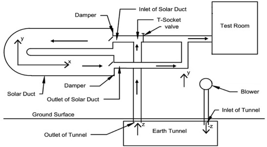
The experimental setup for the system consists of EAHE coupled with SAHD connected to the north side of the testing room. The test room (4.3 m × 3.8 m × 3.05 m) has two windows (1.52 m × 1.22 m) on the east and north facing wall and a door (1.82 m × 0.91 m) on the west facing wall. To prevent the ambient heat losses, thermocol insulation was placed on the interstices around the door as well as on the glass panes of windows. The experimental setup, as shown in Fig. 2 , comprises horizontal PVC pipe (φ 0.1 m, 60 m length) buried on a flat land, dry soil at a depth of 3.7 m. At the inlet, the open end of this pipe is connected to 0.75 kW single phase motorized, 2800 RPM, 0.0945 m3 /s blower with the help of a vertical pipe. At its rated speed, the blower runs at 230 V and provides maximum flow velocity of 12 m/s inside the EAHE PVC pipe. Low ranges of air flow velocity (2.5 m/s, 3.5 m/s and 5 m/s) can be achieved by reducing voltage conditions. The outlet pipe of EAHE was connected to a U-shaped duct (12.2 m long having 0.0645 m2 cross-sectional area) with the help of T-socket as shown in Fig. 3 . This galvanized iron duct was used for the solar air heating purpose as the outer surface of the entire duct was painted black so as to absorb most of the solar radiation falling on it. To regulate the air flow, dampers were provided at the inlet and outlet of both EAHE and SAHD. Three different cases, as discussed in Section 4 , were generated by changing the flow direction with the help of dampers and valves as shown in Fig. 3 . The flow velocity would be different, but flow rate would be same through EAHE pipe as well as SAHD. Ambient air was forced through the EAHE with the help of blower. Air flow velocity through the pipe could be varied by changing the blower RPM with the help of an auto transformer (single phase, 0–270V, 2A maximum current, with a least count of 1V). Seven Resistance Temperature Detectors (RTD) (T0 to T6 ) were inserted at a fixed distance along the depth of pipe at 3.7 m, 3.04 m, 2.43 m, 1.82 m, 1.21 m, 0.60 m, and 0 m, respectively. Nine RTDs (T7 –T15 ) were also inserted at the center of EAHE pipe along the length at a horizontal distance of 0.2 m, 1.7 m, 4.7 m, 9.3 m, 15.1 m, 24.2 m, 34.0 m, 44.4 m, and 60.0 m respectively. T0 –T6 measures the soil temperatures at different depths, while T7 –T15 measures the air temperature along the length of pipe. At the inlet and outlet of SAHD, two RTDs were mounted to measure the temperature of air at that point. Pyranometer was mounted on a weather station, which gives solar radiation on hourly basis. A calibrated thermo hygrometer (make: Fluke-971, temperature accuracy of ±0.1 °C, temperature and relative humidity resolution of 0.1 °C and 0.1% respectively) was used to measure accurate relative humidity and temperature of air inside the test room and outlet of EAHE. Air flow velocities were measured with the help of a vane probe type anemometer (make: Lutron, model: AM-4201) having a range of 0.4–30.0 m/s with a least count of 0.1 m/s. Digital energy meter (make: Powertech Measurement System, type: PTS-01) was used to measure the electrical energy consumption of the blower.
|
|
|
Fig. 2. Experimental set-up of EATHE coupled with solar air heating duct.
|
|
|
|
Fig. 3. Schematic diagram of the experimental setup.
|
4. Testing methodology
As discussed in Section 2 , EAHE is simulated with and without SAHD (Case II and Case III). During the experimentation, these scenarios were taken as different test cases as described below:
- Case-I (Operated on 6 Jan, 10 Jan and 20 Jan): In this case, which is treated as base case, EAHE and SAHD were not functional. Here, only thermal conditions of the room and ambient were monitored.
- Case-II (Operated on 7 Jan, 11 Jan and 21 Jan): In this case heated air (conditioned air) from EAHE was directly supplied to the room and SAHD was not functional.
- Case-III (Operated on 8 Jan, 12 Jan and 22 Jan): Here the heated air (conditioned air) from EAHE was allowed to pass through SAHD for further heating and then supplied to the room.
The system testing was conducted from 3rd January to 27th February 2013 for 8 hour duration daily from 9 a.m. to 5 p.m. System remained closed from 6 p.m. to 9 a.m. every day, allowing the soil to get regenerated. The flow velocity of air through the EAHE was maintained at 2.5 m/s, 3.5 m/s and 5 m/s. For each case, the observed values of all the temperatures (T0 to T6 , T7 to T15 , ambient, EAHE outlet and test room), solar irradiation, relative humidity and electrical consumption of blower were recorded on an hourly basis.
5. Experimental validation and performance analysis
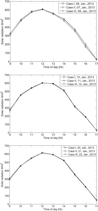
TRNSYS-based modeling and simulation are validated by taking observations on an actual EAHE with SAHD fabricated at Ajmer, India, as shown in Fig. 2 . For three consecutive days in January 2013, system performance has been evaluated by varying the velocities for three different cases. It is essential to mention here that the experimentation continued for one month on all the three cases, but only those observed values have been taken for which a close relation between the solar radiation, temperature and relative humidity of ambient air was found, as shown in Fig. 4 and Fig. 5 . The maximum difference in solar radiation, relative humidity and temperature of ambient air for all the three cases investigated (total 8 h daily) was ±3%, ±3% and ±1.6 °C respectively. It validates the identical ambient conditions for all three cases at any hour of operation, thus ensuring uniform thermal loading of the research room in order to evaluate the performance of each case.
|
|
|
Fig. 4. Intensity of solar radiation in January 2013 for different cases.
|
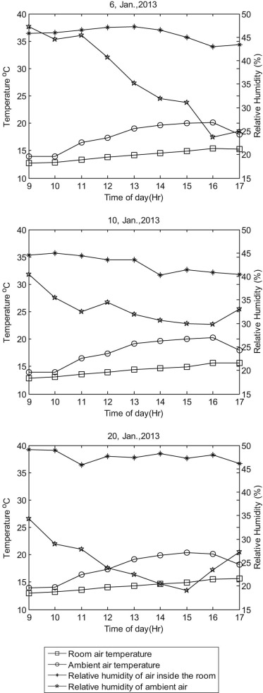
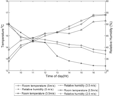
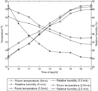
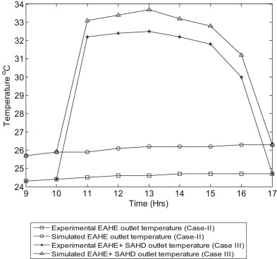
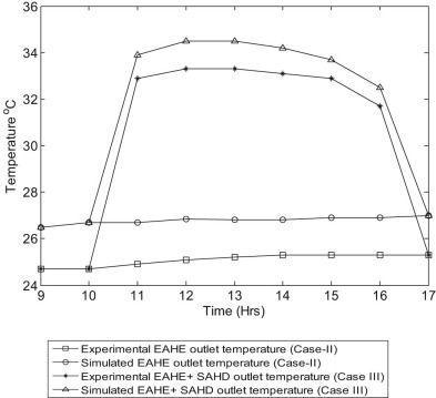
As discussed earlier, the EAHE was put into use during daytime from 9.00 a.m. to 5.00 p.m., in January. Fig. 5 shows that on 6, 10 and 20 Jan, the ambient air temperature and room air temperature range between 13.9 °C and 20.4 °C, and 12.7 °C–15.7 °C, respectively, during Case-I. For the inlet flow velocity of 5 m/s, Fig. 8 shows that on 7 Jan and 8 Jan the temperature of air at the outlet of EAHE varied between 24.3–24.7 °C and 24.3–32.5 °C experimentally during Case-II and Case-III respectively. Therefore a higher air temperature (1.1–3.5 °C) of test room was observed in Case-III as compared to Case-I. Case-II also resulted in slightly higher room temperature (0.9 °C to 1.5 °C) as compared to the base case. It was also inferred from Fig. 5 , Fig. 6 and Fig. 7 that relative humidity of air inside the room on 6, 7 and 8 Jan had a variation of 43.0–47.3%, 32.1–49.9% and 24.2–49.7% during Case-I, Case-II and Case-III respectively. It reveals that the coupling of SAHD with EAHE system increased the outlet temperature by 6–9 °C, thus confirming the significant improvement in the heating potential of the coupled system. The simulated results for EAHE outlet temperature are also shown for both cases in Fig. 8 . The results are within the close agreement with the experimental results with variation of 2.71 to 6.10%. This error may occur due to the variation in coefficient of friction of materials used in simulation, improper insulation of pipes and irregularities such as fitting and joints in experimental setup.
|
|
|
Fig. 5. Thermal performance of Case-I of operation in January 2013.
|
|
|
|
Fig. 6. Room temperature and relative humidity for different velocities for Case-II in January 2013.
|
|
|
|
Fig. 7. Room temperature and relative humidity for different velocities for Case-III in January 2013.
|
|
|
|
Fig. 8. EAHE and EAHE + SAHD outlet temperature (simulated and experimental) for an inlet velocity of 5 m/s.
|
The inlet velocity was changed to 3.5 m/s on 10, 11 and 12 Jan 2013. As shown in Fig. 9 the temperature of air at the outlet of EAHE varied between 24.5–25.3 °C and 24.5–33.4 °C experimentally during Case-II and Case-III, respectively, for flow velocity 3.5 m/s. Temperature of air inside the room varied between 12.7–15.3 °C, 14.9–19.1 °C and 15.0–20.8 °C during the operation of Case-I, Case-II and Case-III, respectively, as shown in Fig. 6 and Fig. 7 . It was found that the EAHE outlet temperature was 0.5–1.0 °C higher for flow velocity of 3.5 m/s as compared to 5.0 m/s. Fig. 5 , Fig. 6 and Fig. 7 also reveal that the relative humidity of room air ranges between 40.3–44.9%, 37–49.3% and 30.9–44.6% during Case-I, Case-II and Case-III respectively. The simulated results for EAHE outlet temperature show an error of 5.2–7.4% for Case II and 2.37–3.6% for Case III as shown in Fig. 9 .
|
|
|
Fig. 9. EAHE and EAHE + SAHD outlet temperature (simulated and experimental) for an inlet velocity of 3.5 m/s.
|
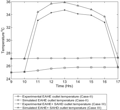
Fig. 5 , Fig. 6 and Fig. 7 show the results for an inlet velocity of 2.5 m/s, on 20, 21 and 22 Jan. Case-I resulted into a variation in room air temperature between 13 °C and 15.7 °C, with relative humidity that varied from 46.1% to 49.4%. Case-II had slightly higher room air temperature (0.4 °C to 1 °C) and relative humidity 3%–11% lesser than the base case. During Case-II, room air temperature and relative humidity varied between 13.8 °C and 16.8 °C and 50.3% and 38.6%, respectively. Fig. 5 , Fig. 6 and Fig. 7 reveal that during Case-III, the room air temperature was 0.9 °C–2.7 °C higher and the relative humidity was 3–12% lesser than the base case. Room air temperature and its relative humidity lied between 14.1 °C and 19.3 °C and 48.4% and 33.9%, respectively, during Case-III. The temperature of air at the outlet of EAHE ranges between 24.9–25.8 °C and 24.7–34.7 °C experimentally during Case-II and Case-III respectively as shown in Fig. 10 . The error obtained by validating with simulation gives the range from 5.1 to 7.91% and from 2.58 to 3.77 % for Case II and Case III respectively.
|
|
|
Fig. 10. EAHE and EAHE + SAHD outlet temperature (simulated and experimental) for an inlet velocity of 2.5 m/s.
|
The heating capacity (kWh) of the EAHE and SAHD for the experimental investigation has been calculated by following equation for different flow velocities.
|
|
( 1) |
where is the mass flow rate of air in kg/s, Ca is the specific heat of air in kJ/kg K, and ΔT is the difference temperature between ambient air temperature (inlet of EAHE) and outlet temperature of EAHE in Case-II, while its the temperature difference between SAHD inlet temperature and outlet temperature (in room) in Case-III. The coefficient of performance (COP) has been calculated as the thermal heat gain divided by the blower energy consumption of the system as shown in Table 2 . It is observed from Table 2 that in Case-II, the total heating capacity on 7 Jan, 11 Jan and 21 Jan was calculated as 1213.044 kWh, 1294.312 kWh and 1360.104 kWh for air velocity of 5 m/s, 3.5 m/s and 2.5 m/s with corresponding COP as 2.807, 2.996 and 3.148 respectively. In Case-III on 8 Jan, when SAHD was coupled, the heating capacity for EAHE (1195.631kWh) was increased to 2413.256 kWh for 5 m/s air velocity, which gives the COP of 5.586. A similar trend was observed on 12 Jan (Case-III) where the heating capacity of EAHE increased from 1273.134 to 2569.497 kWh for 3.5 m/s air velocity. During the same case, the heating capacity of the system was further improved on 22 Jan to 2723.572 kWh for 2.5 m/s air velocity. This proves that the SAHD and lower velocities increased the heating capacity of the system.
| Experimental date (2013) | Inlet air flow velocity (m/s) | Heating capacity of EATHE (kWh) (a) | Heating capacity of solar air heating duct (kWh) (b) | Total heating capacity of system (kWh) (c = a + b) | COP of system |
|---|---|---|---|---|---|
| 07 Jan (Case-II) | 5.0 | 1213.044 | – | 1213.044 | 2.807 |
| 08 Jan (Case-III) | 5.0 | 1195.631 | 1217.625 | 2413.256 | 5.586 |
| 11 Jan (Case-II) | 3.5 | 1294.312 | – | 1294.312 | 2.996 |
| 12 Jan (Case-III) | 3.5 | 1273.134 | 1296.363 | 2569.497 | 5.947 |
| 21 Jan (Case-II) | 2.5 | 1360.104 | – | 1360.104 | 3.148 |
| 22 Jan (Case-III) | 2.5 | 1348.471 | 1375.101 | 2723.572 | 6.304 |
5.1. Effect of depth of pipe burial
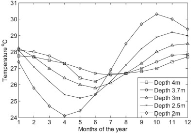
Experimental data recorded in three different days, as discussed in Table 3 , reveal the nature of temperature T0 (which measures the soil temperature at 3.7 m below the ground level). It was observed that the diurnal variation in ambient temperature and solar radiation does not affect T0 . The ground surface temperature was lower than T0 and increases with an increase in depth and finally converges to constant temperature T0 . From the calculations, it was found out that the maximum difference of 14 °C can be achieved between T0 and ground surface. Finally, it was concluded that the depth of 3.7 m and below will be sufficient for pipe burial. The temperature observed at this burial depth is validated with temperature obtained by soil temperature model available in the TRNSYS, where the simulation is performed over the course of whole year, for different burial depths as shown in Fig. 11 . The temperature difference of mere 0.7 °C between simulated data and experimental data is obtained for the month of January.
| Position of temperature sensor | Temperature measured at 1:00 p.m. (°C) | |||
|---|---|---|---|---|
| 07 Jan | 11 Jan | 21 Jan | ||
| Depth-wise (from ground surface) variation of soil temperature | T0 at 3.7 m depth | 27.4 | 27.4 | 27.4 |
| T1 at 3.04 m depth | 25.2 | 25.3 | 25.3 | |
| T2 at 2.43 m depth | 24.3 | 24.5 | 24.5 | |
| T3 at 1.82 m depth | 22.8 | 22.9 | 22.8 | |
| T4 at 1.21 m depth | 21.7 | 21.9 | 21.8 | |
| T5 at 0.60 m depth | 20.2 | 20.4 | 20.2 | |
| T6 at ground surface | 19.1 | 19.5 | 19.3 | |
|
|
|
Fig. 11. Simulated soil temperature at different burial depths.
|
5.2. Effect of air flow velocity
Fig. 8 , Fig. 9 and Fig. 10 depict that with the increase in air velocity, EAHE outlet temperature decreases because of increase of convective heat transfer coefficient by 2.3 times. This also reduces the duration to which the air remains in contact with the ground by a factor of 2.5. Therefore, small increase in EAHE outlet temperature is obtained at air velocity 5 m/s as compared to 3.5 m/s and 2.5 m/s, while the room temperature increases with high velocities (5 m/s) as shown in Fig. 6 and Fig. 7 .
5.3. Effect of pipe length
The effect of pipe length with respect to changes in flow velocities has been shown in Table 4 . It reveals that about 82–85% of the total increase in the temperature of air along the EAHE pipe is achieved at a length of 34 m from the inlet. The temperature growth in the rest of the pipe is infinitesimally small. It is also observed that at 60 m, the outlet temperature of EAHE was higher for 2.5 m/s and 3.5 m/s flow velocity as compared to 5 m/s. For the pipe of 60 m length, temperature rise of 9.6–10.8 °C has been observed experimentally for 2.5–5 m/s air flow velocities. The experimental observations when validated with the simulated data, as shown in Table 4 , found the percentage error within the range of up to 7.9%.
| Section | Air velocity = 5m/s | Air velocity = 3.5m/s | Air velocity = 2.5m/s | ||||||
|---|---|---|---|---|---|---|---|---|---|
| Simulated temperature | Experimental temperature | % difference | Simulated temperature | Experimental temperature | % difference | Simulated temperature | Experimental temperature | % difference | |
| Tinlet | 15.2 | 15.2 | 0.0 | 15.2 | 15.2 | 0.0 | 15.2 | 15.2 | 0.0 |
| T7 | 15.8 | 15.5 | 2.0 | 15.9 | 15.6 | 2.3 | 16.1 | 15.8 | 2.3 |
| T8 | 16.7 | 16.4 | 2.2 | 17.1 | 16.6 | 3.1 | 17.5 | 16.8 | 4.2 |
| T9 | 18.4 | 18.2 | 1.3 | 19.1 | 18.9 | 1.0 | 19.7 | 19.1 | 3.4 |
| T10 | 20.5 | 20.1 | 1.1 | 21.4 | 21.1 | 1.5 | 22.2 | 21.5 | 3.4 |
| T11 | 22.4 | 21.6 | 3.8 | 23.4 | 22.5 | 4.0 | 24.1 | 22.8 | 5.4 |
| T12 | 24.1 | 22.7 | 5.8 | 25.1 | 23.4 | 6.7 | 25.9 | 23.9 | 7.9 |
| T13 | 25.8 | 23.9 | 7.3 | 26.2 | 24.2 | 7.6 | 26.7 | 24.8 | 7.3 |
| T14 | 25.9 | 24.5 | 5.4 | 26.7 | 24.8 | 7.1 | 27.1 | 25.4 | 6.3 |
| T15 | 26.3 | 24.8 | 5.7 | 26.9 | 25.5 | 5.2 | 27.3 | 26 | 4.7 |
6. Error analysis
As per the data given in Figs. 5 –11 and Table 4 , the minimum recorded values of flow velocity, relative humidity and temperature are 2.5 m/s, 15.9 % and 12.7 °C respectively. The least count of measuring instruments for flow velocity, relative humidity and temperature are 0.1 m/s, 0.1% and 0.1 °C respectively. Based on the analysis of errors in the experimental measurements through various instruments employed [18] , the maximum error in measurement is equal to the ratio of the least count of the measuring instrument and minimum recorded value of the parameter. Therefore, uncertainties in the measurement of flow velocity, relative humidity and temperature are estimated as ± 2.0%, ± 0.96% and ± 1.20% respectively. This error investigation explains the instrumental error during the experimentation. Since this research work compares the performance of various cases of operation of EAHE system on the basis of actual experimentally observed values of flow rate, relative humidity and temperature, error analysis given above consists of only the maximum error in measurement part only.
7. Conclusion
In this present work a parametric transient investigation model has been developed for EAHE system in TRNSYS 17 simulation tool and validated it experimentally. The model presented the thermal analysis by varying different parameters like inlet flow velocity, length of pipe and its buried depth. The experimental study has been carried out to find out the effect of mentioned parameters for EAHE coupled with solar air heating duct meant for air heating during the winter season for arid climate of Ajmer (India). The performance for different inlet velocities of 2.5 m/s, 3.5 m/s and 5m/s was compared. It was observed that the heating capacity of the individual EAHE system (Case-II) improves when it is coupled with solar air heating duct (Case-III). For the pipe of 60 m length, temperature rise (EAHE outlet) of 4.6–11 °C and 6.4–17 °C has been observed for Case-II and Case-III, respectively, for different flow velocities during experimental investigation. The results obtained from the experiment data are in good agreement with simulated results within the variation of 0–7.9%. The heating capacity of EAHE system was observed to be between 1213.044–1360.104 kWh and 2413.256–2723.572 kWh during Case-II and Case-III, respectively, for the flow velocity ranging from 2.5 to 5 m/s. It is concluded that the depth of 3.7 m is sufficient for pipe burial and 34 m length of pipe is sufficient to get optimum EAHE outlet temperature. Results showed that there is a drop in EAHE outlet temperature with increase in flow velocity, but increase in room temperature is observed for higher velocities (5 m/s). Experimental results of the study reveal the increase in COP of the system of up to 6.304 with solar air heating duct for the same power consumption. Thus the EAHE system coupled with solar air heating duct is quite effective for air heating during winter as it may reduce the energy consumption and carbon emission of active heating systems in tropical climatic conditions.
Acknowledgments
The authors would like to thank Late Dr. B.K. Maheshwari for his tremendous guidance and support for this work. The authors also thank Mr. Nilesh Purohit for the valuable suggestions and help in this research.
References
- [1] B. Givoni; Passive Low Energy Cooling of Buildings; John Wiley & Sons (1994)
- [2] M. Santamouris; Passive cooling of buildings; Klim. Grej. Hlađenje, 34 (2005), pp. 33–53
- [3] ASHRAE; Handbook of Application; American Society of Heating Refrigerating and Air Conditioning engineers Inc., in, Atlanta, GA (1985)
- [4] V. Bansal, R. Misra, G. Das Agrawal, J. Mathur; Performance analysis of earth–pipe–air heat exchanger for winter heating; Energy Build, 41 (2009), pp. 1151–1154
- [5] F. Al-Ajmi, D.L. Loveday, V.I. Hanby; The cooling potential of earth–air heat exchangers for domestic buildings in a desert climate; Build. Environ, 41 (2006), pp. 235–244
- [6] H. Wu, S. Wang, D. Zhu; Modelling and evaluation of cooling capacity of earth–air–pipe systems; Energy Convers. Manag, 48 (2007), pp. 1462–1471
- [7] G. Mihalakakou, M. Santamouris, D. Asimakopoulos; Modelling the thermal performance of earth-to-air heat exchangers; Sol. Energy, 53 (1994), pp. 301–305
- [8] G. Mihalakakou, M. Santamouris, D. Asimakopoulos, I. Tselepidaki; Parametric prediction of the buried pipes cooling potential for passive cooling applications; Sol. Energy, 55 (1995), pp. 163–173
- [9] J. Pfafferott; Evaluation of earth-to-air heat exchangers with a standardised method to calculate energy efficiency; Energy Build, 35 (2003), pp. 971–983
- [10] P. Cui, H. Yang, Z. Fang; Numerical analysis and experimental validation of heat transfer in ground heat exchangers in alternative operation modes; Energy Build, 40 (2008), pp. 1060–1066
- [11] M. Santamouris, G. Mihalakakou, A. Argiriou, D.N. Asimakopoulos; On the performance of buildings coupled earth to air heat exchangers; Sol. Energy, 54 (1995), pp. 375–380
- [12] M.K. Ghosal, G.N. Tiwari, D.K. Das, K.P. Pandey; Modeling and comparative thermal performance of ground air collector and earth air heat exchanger for heating of greenhouse; Energy Build, 37 (2005), pp. 613–621
- [13] M.S. Sodha, A.K. Sharma, S.P. Singh, N.K. Bansal, A. Kumar; Evaluation of an earth-air tunnel system for cooling/heating of a hospital complex; Build. Environ, 20 (1985), pp. 115–122
- [14] S. Jakhar, R. Misra, V. Bansal, M.S. Soni; Thermal performance investigation of earth air tunnel heat exchanger coupled with a solar air heating duct for northwestern India; Energy Build, 87 (2015), pp. 360–369
- [15] V. Badescu; Simple and accurate model for the ground heat exchanger of a passive house; Renew. Energy, 32 (2007), pp. 845–855
- [16] R. Kumar, S. Ramesh, S.C. Kaushik; Performance evaluation and energy conservation potential of earth–air–tunnel system coupled with non-air-conditioned building; Build. Environ, 38 (2003), pp. 807–813
- [17] TRNSYS 17, Transient System Simulation Program, Solar Energy Laboratory, University of Wisconsin, Madison (USA) <http://www.trnsys.com >.
- [18] J.P. Holman, W.J. Gajda; Experimental Methods for Engineers, vol. 2, McGraw-Hill, New York (1994)
Document information
Published on 10/04/17
Licence: Other
Share this document
Keywords
claim authorship
Are you one of the authors of this document?

