"Non quia difficilia sunt non audemus, sed quia non audemus difficilia sunt."
Seneca (CIV,26)
Acknowledgement
It has been a long and challenging way, but, fortunately, during these years I have met many people, who encouraged me to go ahead and taught me not to give up. I am very grateful for this.
I would like to thank my advisor, Prof. Eugenio Oñate, for giving me the opportunity to study in CIMNE. During the years spent at this research center, I could find many sources of knowledge and inspiration, that I will take with me wherever I will be in the future. A special thanks goes to my co-advisor, Prof. Antonia Larese, for introducing me to the field of computational mechanics and for supporting me in the most important moments of this experience. I would like to thank those colleagues of CIMNE, who with great patience, helped me dedicating part of their time, Riccardo, Stefano, Charlie, Pablo, Lorenzo, Jordi and Alessandro.
I would like to thank Prof. Massimiliano Cremonesi for his supervision and kind welcome during my visit at the Department of Civil and Environmental Engineering, at Politecnico di Milano. I want to express my gratitude to Dr. Fausto Di Muzio for his kindness and warming welcome during my brief stay at Nestlé. This experience allowed me to look at the research world from a different perspective and to recognize how important is to conjugate fundamental research with more practical applied aspects. In this respect, I would like to thank Dr. Julien Dupas for his collaboration and support in providing some experimental data.
I have been enough fortunate to be part of the European project T-MAPPP, which greatly contributed not only to the development of my technical knowledge, but also of my soft skills. I would like to thank all the researchers involved in the project. In particular, Prof. Stefan Luding and Prof. Vanessa Magnanimo, for the valuable discussions and the interest shown in my work; Yousef, Kostas, Kianoosh, Behzad, Somik, Sasha and Niki, because without them it would have not been the same.
A special thank you goes to all the people who made my day with a smile and let me see the positive side in any situation. Thank you Josie, Manu, Edu, Vicente, Nanno, Giulia, Eugenia and Alessandra.
Last but not least, all my gratitude goes to my family: Marta, Gianni and Claudia, for their wholehearted support and love.
The research was supported by the Research Executive Agency through the T-MAPPP project (FP7 PEOPLE 2013 ITN-G.A.n607453).
Resumen
El manejo, el transporte y el procesamiento de materiales granulares y en polvo son operaciones fundamentales en una amplia gama de procesos industriales y de fenómenos geofísicos. Los materiales particulados, que pueden encontrarse en la naturaleza, generalmente están caracterizados por un tamaño de grano, que puede variar entre varios órdenes de magnitud: desde el nanómetro hasta el orden de los metros. En función de las condiciones de fracción volumétrica y de deformación de cortante, los materiales granulares pueden tener un comportamiento diferente y a menudo pueden convertirse en un nuevo estado de materia con propiedades de sólidos, de líquidos y de gases. Como consecuencia, tanto el análisis experimental como la simulación numérica de medios granulares es aún una tarea compleja y la predicción de su comportamiento dinámico representa aun hoy día un desafío muy importante. El principal objetivo de esta monografía es el desarrollo de una estrategia numérica con la finalidad de estudiar el comportamiento macroscópico de los flujos de medios granulares secos en régimen cuasiestático y en régimen dinámico. El problema está definido en el contexto de la mecánica de medios continuos y las leyes de gobierno están resueltas mediante un formalismo Lagrangiano. El Metodo de los Puntos Materiales (MPM), método basado en el concepto de discretización del cuerpo en partículas, se ha elegido por sus características que lo convierten en una técnica apropiada para resolver problemas en grandes deformaciones donde se tienen que utilizar complejas leyes constitutivas. En el marco del MPM se ha implementado una formulación irreducible que usa una ley constitutiva de Mohr-Coulomb y que tiene en cuenta no-linealidades geométricas. La estrategia numérica está verificada y validada con respecto a tests de referencia a resultados experimentales disponibles en la literatura. También, se ha implementado una formulación mixta para resolver los casos de flujo granular en condiciones no drenadas. Por último, la estrategia MPM desarrollada se ha utilizado y evaluado con respecto a un estudio experimental realizado para caracterizar la fluidez de diferentes tipologías de azúcar. Finalmente se presentan unas observaciones y una discusión sobre las capacidades y las limitaciones de esta herramienta numérica y se describen las bases para una investigación futura.
Abstract
Bulk handling, transport and processing of granular materials and powders are fundamental operations in a wide range of industrial processes and geophysical phenomena. Particulate materials, which can be found in nature, are usually characterized by a grain size which can range across several scales: from nanometre to the order of metre. Depending on the volume fraction and on the shear strain conditions, granular materials can have different behaviours and often can be expressed as a new state of matter with properties of solids, liquids and gases. For the above reasons, both the experimental and the numerical analysis of granular media is still a difficult task and the prediction of their dynamic behaviour still represents, nowadays, an important challenge. The main goal of the current monograph is the development of a numerical strategy with the objective of studying the macroscopic behaviour of dry granular flows in quasi-static and dense flow regime. The problem is defined in a continuum mechanics framework and the balance laws, which govern the behaviour of a solid body, are solved by using a Lagrangian formalism. The Material Point Method (MPM), a particle-based method, is chosen due to its features which make it very suitable for the solution of large deformation problems involving complex history-dependent constitutive laws. An irreducible formulation using a Mohr-Coulomb constitutive law, which takes into account geometric non-linearities, is implemented within the MPM framework. The numerical strategy is verified and validated against several benchmark tests and experimental results, available in the literature. Further, a mixed formulation is implemented for the solution of granular flows that undergo undrained conditions. Finally, the developed MPM strategy is used and tested against the experimental study performed for the characterization of the flowability of several types of sucrose. The capabilities and limitations of this numerical strategy are observed and discussed and the bases for future research are outlined.
List of Symbols
| : | time; |
| : | internal friction angle; |
| : | particle diameter; |
| : | particle density; |
| : | shear rate; |
| : | undeformed configuration; |
| or : | deformed configuration at time ; |
| or : | deformed configuration at time ; |
| : | characteristic function in the Generalized Interpolation Material Point Method; |
| : | particle volume; |
| : | current particle domain; |
| : | current domain occupied by the continuum; |
| : | shape function relative to node evaluated at position at position ; |
| : | gradient shape function relative to node evaluated at position at position ; |
| : | gradient shape function from node-based calculation; |
| : | gradient shape function evaluated in Dual Domain Material Point Method; |
| : | relative to the material point ; |
| : | relative to the node ; |
| : | relative to the node at time ; |
| : | relative to the node at time and iteration ; |
| : | displacement vector; |
| : | increment displacement vector; |
| : | velocity vector; |
| : | acceleration vector; |
| : | pressure; |
| : | momentum vector; |
| : | inertia vector; |
| : | mass; |
| : | stability parameters of Bossak method; |
| : | vector of unknown incremental displacement; |
| : | tangent matrix of the linearised system of equation; |
| : | residual vector of the linearised system of equation; |
| : | local coordinates relative to a material point; |
| : | on-negative locality coefficient in Local Maximum Entropy technique; |
| : | measure of nodal spacing in Local Maximum Entropy technique; |
| : | dimensionless parameter in Local Maximum Entropy technique; |
| : | total deformation gradient; |
| : | determinant of the total deformation gradient; |
| : | incremental deformation gradient; |
| : | First Piola-Kirchhoff stress tensor; |
| : | Second Piola-Kirchhoff stress tensor; |
| : | Kirchhoff stress tensor; |
| : | Cauchy stress tensor; |
| : | specific strain energy function; |
| : | rotation tensor; |
| : | rotation tensor from polar decomposition of ; |
| : | right stretch tensor; |
| : | left stretch tensor; |
| : | right Cauchy-Green tensor; |
| : | first principal invariant of ; |
| : | first invariant of ; |
| : | left Cauchy-Green tensor; |
| : | Lame constant; |
| : | bulk modulus; |
| : | shear modulus; |
| : | material incremental constitutive tensor; |
| : | spatial incremental constitutive tensor; |
| : | symmetric second order unit; |
| : | fourth order identity tensor; |
| : | fourth order symmetric identity tensor; |
| : | fourth order deviatoric projector tensor; |
| : | symmetrical spatial velocity gradient; |
| : | rate of deformation tensor; |
| : | spin tensor; |
| : | velocity gradient tensor; |
| : | volumetric part of ; |
| : | deviatoric part of ; |
| : | deviatoric part of ; |
| : | elastic part of ; |
| : | plastic part of ; |
| : | volume preserving part of ; |
| : | flow stress; |
| : | isotropic hardening; |
| : | hardening parameter; |
| : | plastic multiplier; |
| : | unit vector of ; |
| : | in trial state; |
| : | trace of ; |
| : | metric tensor in current configuration; |
| : | spatial algorithmic elastoplastic moduli; |
| : | cohesion; |
| : | dilation angle; |
| : | normal stress; |
| : | principal Hencky strain; |
| : | Hencky elastic constitutive tensor; |
| : | elasto-plastic fourth order constitutive tensor; |
| : | consistent elasto-plastic tangent; |
| : | eigenvalues vector of ; |
| : | eigenvector vector of ; |
| : | eigenbases vector of ; |
| : | eigenvector vector of ; |
| : | eigenbases vector of ; |
| : | body; |
| : | 3D Euclidean space; |
| : | real coordinate space in 3D; |
| : | mass density; |
| : | mass density in underformed configuration; |
| : | body force; |
| : | gravity; |
| : | Neumann boundary in deformed configuration; |
| : | Dirichlet boundary in deformed configuration; |
| : | prescribed normal tension on Neumann boundary; |
| : | prescribed displacement on Dirichlet boundary; |
| : | displacement weight function; |
| : | pressure weight function; |
| : | displacement space; |
| : | displacement finite element space; |
| : | in the finite element space; |
| : | geometrical representation of ; |
| : | finite volume assigned to a material point; |
| : | Hilbert space; |
| : | differential volume in deformed configuration; |
| : | differential boundary surface in deformed configuration; |
| : | differential volume in undeformed configuration; |
| : | material gradient operator; |
| : | spatial gradient operator; |
| : | symmatric part of gradient; |
| : | fourth order incremental constitutive tensor relative to ; |
| : | fourth order incremental constitutive tensor relative to ; |
| : | fourth order incremental constitutive tensor relative to ; |
| : | matrix form of ; |
| : | deformation matrix; |
| : | geometric stiffness matrix; |
| : | material stiffness matrix; |
| : | static part of ; |
| : | dynamic part of ; |
| : | pressure space; |
| : | vector of unknown pressure; |
| : | geometric stiffness matrix in mixed formulation; |
| : | material stiffness matrix in mixed formulation; |
| : | residual vector relative to the momentum balance equation; |
| : | residual vector relative to the pressure continuity equation; |
| : | residual vector relative to the stabilization term; |
| : | mass matrix; |
| : | mass matrix relative to the stabilization term; |
| : | residual vector relative to the stabilization term; |
| : | stabilization parameter; |
| : | mixed terms in the mixed formulation |
| : | diameter at which 10% of the sample's mass is comprised of particles with a diameter less than this value; |
| : | diameter at which 50% of the sample's mass is comprised of particles with a diameter less than this value; |
| : | diameter at which 90% of the sample's mass is comprised of particles with a diameter less than this value; |
| : | matrix form of in axisymmetric case; |
| : | tangent stiffness matrix in axisymmetric case; |
| : | geometric stiffness matrix in axisymmetric case; |
| : | material stiffness matrix in axisymmetric case; |
1 Introduction
Bulk handling, transport and processing of particulate materials, such as, granular materials and powders, are fundamental operations in a wide range of industrial processes [1] or geophysical phenomena and hazards, such as, landslides, debris flows, etc. [2]. Particulate systems are difficult to handle and they can show an unpredictable behaviour, representing a great challenge in the industrial production, concerning both design and functionality of unit operations in plants, but also in the research community of Powders and Grains [3,4]. Granular materials and powders consist of discrete particles such as, e.g., separate sand-grains, agglomerates (made of several primary particles), natural solid materials like sandstone, ceramics, metals or polymers sintered during additive manufacturing. The primary particles can be as small as nano-metres, micro-metres, or millimetres [5] covering multiple scales in size and a variety of mechanical and other interaction mechanisms, such as, friction and cohesion [6], which become more and more important the smaller the particles are. All those particle systems have a particulate, usually disordered, possibly inhomogeneous and often anisotropic micro-structure; nowadays, the research community is working actively in order to have a deeper understanding and aware knowledge of bulk behaviour affected by micro-scale parameters. Indeed, particle systems as bulk show a completely different behaviour as one would expect from the individual particles. Collectively, particles either flow like a fluid or rest static like a solid. In the former case, for rapid flows, granular materials are collisional, inertia dominated and compressible similar to a gas. In the latter case, particle aggregates are solid-like and, thus, can form, e.g., sand piles or slopes that do not move for long time. Between these two extremes, there is a third flow regime, dense and slow, characterized by the transitions (i) from static to flowing (failure, yield) or vice-versa (ii) from fluid to solid (jamming). At the particle and contact scale, the most important property of particle systems is their dissipative, frictional, and possibly cohesive nature. In this context, dissipation shall be understood as kinetic energy, at the particle scale, which converts into heat, for instance, due to plastic deformations. The transition from fluid to solid can be caused by dissipation alone, which tends to slow down motion. The transition from solid to fluid (start of flow) is due to failure and instability when dissipation is not strong enough and the solid yields and transits to a flowing regime.
In this Chapter, the granular flow theory is presented more in detail and the main attempts, available in the literature, for the modelling of granular matter behaviour in the different regimes are discussed. Afterwards, objectives and layout of the current monograph are presented.
1.1 The granular flows
The heavy involvement of particle materials in many different industrial processes makes the granular matter, nowadays, a remarkable object of study. Particulate materials exist in large quantity in nature and it is established that most of the industrial processes, such as, pharmaceutical, agricultural, chemical, just to cite a few, deal with materials that are particulate in structure. In the industrial field, dealing with processes at large scales and huge quantities of raw material, any issue, encountered in the production line, may cause losses in terms of productivity, and, thus, of money. During the last decades, it has been documented that also in processes of granular matters, a lack of knowledge implies non-optimal production quality. In older industrial surveys, Merrow [7] found that the main factor causing long start-up delays in chemical plants is represented by the processing granular materials, especially due to the lack of reliable predictive models and simulations, while Ennis et al. [8] reported that 40 of the capacity of industrial plants is wasted because of granular solid phenomena. More recently, Feise [9] analysed the changes in chemical industry and predicted an increase in particulate solids usage along with new challenges due to new concepts like versatile multi-purpose plants, and fields like nano and bio-technology. For these reasons, it is clear that it is fundamental to have a better understanding of particulate materials behaviour under different conditions and to be able to improve the production quality through experimental campaigns and numerical modelling works. However, due to the wide variety of intrinsic properties of particulate materials a unified constitutive description, under any condition, has not been established yet.
With granular flow, we refer to motions where the particle-particle interactions play an important role in determining the flow properties and the flow patterns which are quite different from those of conventional fluids. The most evident differences between granular systems and simple fluids affecting the macroscopic properties of the flow, as pointed out in [10], are:
- The size of grains is typically approximately more massive and voluminous than a water molecule. As both fluid and particle motions can be studied according to the laws of classical mechanics, this is not a fundamental difference, but could represent an important factor while evaluating the applicability of continuum hypothesis, as explained below;
- In granular systems, when granules collide, a loss of kinetic energy converted in true heat is observed. This difference determines the main feature which deeply distinguishes the granular flows modelling from the fluid flows one;
- In nature, grains are not identical: particle shape, particle roughness and solid density are only some of the particle properties which characterize a grain from the other. As real particles are not exactly spherical and typically the surface is rough, in grain-grain interactions frictional forces and torque are created and grains rotate during the collision.
The above comparison is useful to emphasise that the main assumptions on the basis of fluid flow modelling can not coincide with those of granular flow modelling. Further, this comparison can also be useful to set the bounds of the continuum assumptions enforceability. Three length scales have to be considered for the definition of these hypotheses. The first one is related to the particle size. Typically the value of density in grain systems is much smaller than in molecular fluids; this means that, for instance, in a cubic mm of fluids the number of molecules is much higher than the number of grains. If a macroscopic quantity changes significantly over a 1 mm of length, the variation over the molecules is small, but in the granular materials, if the number of particles in a 1 mm is low, a bigger variation is registered falling out of the continuum assumptions. The second length is related to the container confining the system and the third one to the inelasticity in grain-grain collisions. The latter can be defined as the radius of the pulse, related to a degradation of factor of the total kinetic energy in a system of grains after a localized input of energy. If the inelasticity is not small this length covers just a few particles. This implies substantial changes in macroscopic quantities over distances measured over a small number of grain diameters, which do not allow to respect the continuum assumptions.
When one wants to study the flow of granular materials has to bear in mind that the bulk in motion is represented by an assembly of discrete solid particles interacting with each other. Depending on the intrinsic properties of the grains and the macroscopic characteristic of the system (i.e. geometry, density, velocity gradient), the internal forces can be transmitted in different ways within the granular material. Depending on this, three main flow patterns can be observed experimentally and numerically [11]. At large solids concentration and low shear rate, the stresses are not evenly distributed, but are concentrated along networks of particles, called force chains. The force chains are dynamic structures, which rotate, become unstable and, finally, collapse as a result of the shear motion. When granular material fails it is observed that the failure occurs along narrow planes, within the material, which have not infinitesimal thickness, but are zones of the order of ten particles across called shear bands. Within the shear bands, the stresses are still distributed along the force chains and the shear and normal stresses are related in non-cohesive material as
|
|
(1.1) |
where is the internal friction angle. Observing Equation 1.1, it is noted that depends on the geometry of the force chains; thus, the friction-like response of the bulk is a result of the internal structure of force chains, as well.
This flow pattern takes the name of Quasi-static regime because the rate of formation of the force chain divided by their lifetime is independent on the shear rate and with this also the generated stresses. If on one hand, the shear rate does not affect the response of the system, on the other hand, it is worth highlighting that the inter-particle stiffness k plays an important role, as the stresses within the force chains show a linear dependence with k. The inter-particle stiffness, in turn, can be expressed as a linear function of the Young modulus E of the material and also depends on the local radius of curvature, thus, on the geometry of the contact. Bathurst and Rothenburg [12] have derived an expression for the bulk elastic modulus K, which linearly depends on the stiffness and can be used in the definition of the sound speed in a static granular material. As shown in the data of Goddard [13] and Duffy Mindlin [14], the wave velocity is dependent on the pressure applied to the bulk assembly. Thus, increasing the confining pressure, the elastic bulk modulus increases along with the inter-particle stiffness k and the force chains lifetime.
Until the shear rates are kept low, the inertia effects are small and force chains are the only mechanism available to balance the applied load. Increasing the shear rate, the particles are still locked in force chains, but the forces generated have to take into account the inertia introduced in the system. Further increasing , the inertial component of the internal forces linearly increases with the shear rate and when these are comparable with the static forces the flow transition to the Inertial regime takes place. The Inertial regime encompasses flows where force chains cannot form and the momentum is transported largely by particle inertia. In this regime, the shear stresses are independent of the stiffness, but dependent on the second power of the shear rate, as expressed in the Bagnold scaling [15], where and are the particle diameter and particle density, respectively. Even if force chains are not present, multiple simultaneous contacts between the particles still coexist allowing longer contact period . By defining with the binary contact time, i.e., the duration of a contact between two freely colliding particles, the ratio . If this ratio has the value of 1, the dominant particle collisions are binary and instantaneous and the flow is defined with the name of Rapid Granular Flow [16], which can be considered as an asymptotic case of the Inertial Regime. This flow path is controlled by the property of granular temperature, which represents a measure of the unsteady components of velocity. The granular temperature is generated by the shear work and it drives the transport rate in two principal modes of internal (momentum) transport: a collisional and a streaming mode. In the first case, the granular temperature provides the relative velocity that drives particle to collide; while, in the second case, it generates a random velocity that makes the particles move relatively to the velocity gradient. In the Rapid Granular Flow the coexistence of contact and streaming stresses can be observed; obviously, the collisional mode dominates at high concentrations, while the streaming mode at low concentrations. It is generally assumed that, at small shear rates, a flow behaves quasi-statically, and that by increasing the shear rate, one will eventually end up in the Rapid Flow regime. As pointed out by Campbell [11], the transition through the regimes is regulated by the volume fraction and the shear rate. However, by fixing the first or the second field, the transition may take place in a different way.
1.2 Granular flow modelling
Despite the prevalence of granular materials in most of the industrial applications, there is still a large discrepancy between results predicted by analytical or numerical solutions and their real behaviour [17]. Thus, structures and facilities for dealing with particulate material handling are not functioning efficiently and there is always a probability of structural failure and an unexpected arrest of the production line. Due to the intrinsic nature of granular materials, the prediction of their dynamic behaviour represents nowadays an important challenge for two main reasons. Firstly, the characteristic grain size has an excessively wide span: from nanoscale powders (such as colloids with a typical size of nanometre) to large blocks of coal extracted from mines. This feature gives rise to some difficulties in defining a unique model able to properly work across many scales. Secondly, although these materials are solid in nature, they behave differently in various circumstances and often changes in a new state of matter with properties of solids, liquids and gases [17]. Indeed, as with solids, they can withstand deformation and form heap; as with liquids, they can flow; as with gases, they can exhibit compressibility. This second aspect makes the modelling of granular matter even more difficult to define, as the macroscopic behaviour is affected by a set of microscopic parameters which often are not directly measurable from laboratory tests. Nevertheless, these challenges encouraged the research community to work actively in the particle technology field, developing and improving several numerical and experimental techniques for the characterization of granular materials.
As explained in Section 1.1, a granular flow can undergo three main regimes in different domains of volume fraction and shear rate. When the grains have very little kinetic energy, the assembly of the particle is dense, and if the structure is dominated by the force chains the response of the bulk is independent on the shear rate. In this case, the flow pattern is known as Quasi-static regime and the behaviour is well described by classical models used in soil mechanics [18]. On the other hand, if a lot of energy is brought to the grains, the system is dilute, granular materials are collisional, inertia-dominated and compressible similar to a gas. In this case, the stresses vary as the square of the shear rate [15] and the flow falls under the Rapid granular flow theory. The principal approach, provided in the literature, for modelling granular flow under these conditions is represented by the Kinetic Theory of granular gases [16]. In the definition of such a model, the formalism of gas kinetic theory is used with the constraint to consider the particles perfectly rigid and the kinetic theory formalism leads to a set of Navier-Stokes equations. Between these two regimes, we can find the dense and slow flow regime, characterized by the presence of multiple particles contact, but also by the absence of force chains. For the modelling of granular flows under this regime, in [19] the constitutive relation of a viscoplastic fluid is proposed, commonly known with the name of rheology. The idea comes from the analogy observed with Bingham fluids, characterized by a yield criterion and a complex dependence on the shear rate. By assuming the particles perfectly rigid and a homogeneous and steady flow, a set of Navier-Stokes equations is provided. Despite it has been demonstrated that the model can successfully reproduce the results of some experimental tests [19], the model can only qualitatively predict the basic features of granular flows. In fact, some phenomena, such as, the formation of shear bands, flow intermittence and hysteresis in the transition solid to fluid and vice-versa, cannot be modelled through the law.
Even if there are models able to predict the flow behaviour in single regimes, a comprehensive rheology, able to gather together all three regimes, is still missing in the literature. Many attempts have been done during the last years. To cite a few of them, it is worth mentioning the contribution of Vescovi and Luding [20] where a homogeneous steady shear flow of soft frictionless particles is investigated; both fluid and solid regimes are considered and merged into a continuous and differentiable phenomenological constitutive relation, with a focus on the volume fraction close to the jamming value. Also Chialvo and coworkers [21] turn the attention to the interface between the quasi-static and the inertial regime in the context of a jamming transition, still neglecting any time dependency (under the assumption of steady-state flow), but considering soft friction particles. Other proposals are based on the relaxation of some hypotheses at the base of the rheology, such as, for instance, the constitutive laws provided by Kamrin et al. [22] where the non-local effects are considered and by Singh et al. [23] where the particle stiffness influence is included in the model.
In order to perform a numerical investigation of the granular flow problem, one has to keep in mind that not only a constitutive model is needed for its accomplishment, but also a numerical technique used to solve the system of algebraic equations which govern the problem. Numerical methods can be distinguished according to the kinematic description adopted and to the spatial and time scales that balance laws are based on. As previously observed, particulate materials can be studied at different scales and depending on this the selection of the numerical technique may change.
Granular materials have a discrete nature and it is of paramount importance to have a clear description at the microscale for a deep understanding of the physics behind the bulk behaviour. In recent decades, the most common and used numerical tool for such investigation is represented by the Discrete Element Method (DEM) [24], which considers a finite number of discrete interacting particles, whose displacement is described by the Newton's equations related to translational and rotational motions.
In the research community, granular materials are studied by using a continuum approach, as well. For instance, all the aforementioned constitutive models, proposed under the condition which range between the Quasi-static regime and Rapid granular flow, are based on a continuous description of the granular matter behaviour. On one hand these approaches, obviously, do not allow to predict the material response on the point, where two particles collide, i.e., at the microscale, but are able to provide a mesoscale response, constant on a representative elemental volume (REV), where the continuum assumptions are still valid [10].
Other methods, available in the literature, are used to scale-up from the micro-level. In this regard, it is worth mentioning the Population Balance Method (PBM) [25], able to describe the evolution of a population of particles from the analysis of single particle in local conditions. For instance, PBM is widely used to track the change of particle size distribution during processes where agglomeration or breakage of particles are involved, by using information, such as, impact velocity distribution, provided by DEM analysis [26,27].
1.3 Objectives
In the present work, we focus on the macroscale analysis of granular flows. More specifically, the current monograph aims at providing a verified and validated numerical model able to predict the behaviour of highly deforming bulk of granular materials in their real scale systems. Some examples, objects of this study, are represented by hopper flows, the collapse of granular columns and measurement of bearing capacity of a soil undergoing the movement of a rigid strip footing. These tests are characterized by some common features which are essential for the definition of the numerical tool to be developed. All the examples of granular flow mentioned above are densely packed with solid concentrations well above 50% of the volume and they can be considered dense granular flow where forces are largely generated by inter-particle contacts. This implies that a collisional state of the matter, where the principal mechanism of momentum transport is based on binary particle contacts, will never be reached. Moreover, in all cases an elastic/quasi-static regime usually coexists with a plastic/flowing regime. In order to be able to model the quasi-static and the flowing behaviours simultaneously in different parts of the material domain, a constitutive law which accounts for both the elastic and plastic regime is needed. The use of viscous fluid materials, as those described by the rheology and its different versions, can predict the granular flow behaviour under the inertial regime. However, the good reliability of these models is still limited to the steady case and to volume fractions whose values never exceed the jamming point. Further, if a viscous material is chosen, some difficulties might be encountered in the evaluation of internal forces where a zero strain rate is present. With the picture described above, the numerical model is conceived in a continuum mechanics framework in order to optimize the high, not to say prohibitive, computational cost which might be induced by the high value of density in the grain system, if a discrete technique is, then, selected. Moreover, the transition between the solid-like and fluid-like behaviour induces large displacement and huge deformation of the continuum which, from the numerical viewpoint, is well established to be tough to handle with standard techniques, such as the well-known Finite Element Method (FEM). Last but not least, not only geometric, but also material non-linearities should be considered. To address to this concern, the choice falls on those elasto-plastic laws, defined within the solid mechanics framework, whose stress response depends on the total strain history and historical parameters characteristic of the material model. The numerical model to adopt has to be based not only on a continuum mechanics framework, but also has to be able to track with high accuracy the huge deformation of the medium and the spatial and time evolution of its own material properties. After a search focused on the numerical model which closest fits with the features outlined above, it is found that the Material Point Method (MPM) [28], a continuum-based particle method, might be a good candidate in solving granular flows problems under multi-regime conditions and an optimal platform for the numerical implementation of new constitutive laws which attempt to include a bridge between different scales (from the particle-particle contact (micro) to the bulk (macro) scale). In the current work, an implicit MPM is developed by the author in the multi-disciplinary Finite Element codes framework Kratos Multiphysics [29,30,31]. Unlike most MPM codes, which make use of explicit time integration, in this monograph it is decided to adopt an implicit integration scheme. The choice is made with the aim of analysing cases characterized by a low-frequency motion and providing results with a higher stability and better convergence properties. Two formulations are implemented within the MPM framework by taking into account the geometric non-linearity, which allows to treat problems of finite deformation, usually not considered in many MPM codes that one can find in the literature. Firstly, an irreducible formulation and a Mohr-Coulomb constitutive law are developed. Further, a mixed formulation is proposed for the analysis of granular flows under undrained conditions, which represents, to the knowledge of the author, an original solution in the context of the MPM technique. The MPM strategy, with both the formulations, is validated by using experimental results or solutions of other studies, available in the literature. Last but not least, as final objective of this monograph, the developed MPM numerical tool is successfully tested in an industrial framework, in the context of a collaboration with Nestlé. A comparison is performed against an unpublished experimental study conducted for the characterization of flowability of several types of sucrose. Advantages and limitations of the numerical strategy provided are observed and discussed.
1.4 T-MAPPP project
The current work has been funded by the T-MAPPP (Training in Multiscale Analysis of MultiPhase Particulate Processes and Systems, FP7 PEOPLE 2013 ITN-G.A. n60) project. This project has been conceived in order to bring together European organizations leading in their respective fields of production, handling and use of particulate systems. T-MAPPP is an Initial Training Network funded by FP7 Marie Curie Actions with 10 full partners and 6 associate partners. The role of the network is to train the next generation of researchers who can support and develop the emerging inter- and supra-disciplinary community of Multiscale Analysis (MA) of multi Phase Particulate Processes. The goal is to develop skills to progress the field in both academia and industry, by devising new multiscale technologies, improving existing designs and optimising dry, wet, or multiphase operating conditions. One aim of the project is to train researchers who can transform multiscale analysis and modelling from an exciting scientific tool into a widely adopted industrial method; in other words, the establishment of an avenue able to increasingly link academic to real world challenges.
1.5 Layout of the monograph
The layout of the document is as follows: in Chapter 2, after a brief review of the state of the art in particle methods, the focus is put on those methods which are more consistently used for the prediction of granular flows behaviour, such as, the Discrete Element Method (DEM), the Particle Finite Element Method (PFEM), the Galerkin Meshless Methods (GMM) and the Material Point Method (MPM). The latter is the chosen approach, used and developed in this monograph. The choice is discussed and the details of the proposed formulations are provided. In Chapter 3 the theory of constitutive laws used in the current work is presented with their implementations under the assumption of finite strains. In Chapter 4 and Chapter 5 an irreducible and a mixed stabilized formulation, respectively, are presented and verified with solid mechanics benchmark examples. Then, in Chapter 6 the numerical model of MPM, presented in the previous chapters, is applied and validated (with experimental and numerical results available in the literature) against granular flow examples, such as, the granular column collapse and the rigid strip footing test. In Chapter 7 the MPM strategy is applied in an industrial framework. The numerical results are compared against experimental measurements performed for the assessment of the flowability performance of different types of sucrose. Finally, in Chapter 8 some conclusions are drawn, where observations and limitations of the numerical strategy are provided, and the bases for future research are outlined.
2 Particle Methods
Computer modelling and simulation are now an indispensable tool for resolving a multitude of scientific and challenging problems in science and engineering. During the last decades the importance of computer-based science has exponentially grown in the engineering field and, nowadays, it is widely adopted in the study of different processes because of its advantages of low cost, safety and efficiency over the experimental modelling. The numerical simulation of solid mechanics problems involving history-dependent materials and large deformations has historically represented one of the most important topics in computational mechanics. Depending on the way deformation and motion are described, existing spatial discretisation methods can be classified into Lagrangian, Eulerian and hybrid ones. Both Lagrangian and Eulerian methods have been widely used to tackle different examples characterized by extreme deformations. In this chapter, firstly, the most common numerical techniques used in the modelling of granular flows are presented. Then, the focus is put on the Material Point Method, which is the object of the present study.
2.1 Lagrangian and Eulerian approaches
In continuum mechanics two fundamental descriptions of the kinematic and the material properties of the body, under analysis, are possible. The first one is represented by the Lagrangian approach. In this case the description is made as the observer were attached to a material point forming part of the continuum. Lagrangian algorithms, traditionally employed in structural mechanics, make use of a moving deforming mesh dependent on the motion of the body and are distinguished by the ease with which the material interfaces can be tracked and the boundary conditions can be imposed. According to [32] three Lagrangian formulations can be defined:
- the Total Lagrangian formulation, where all the variables are written with reference to the undeformed configuration at the initial time
- the Updated Lagrangian formulation, where all the variables are written with reference to the deformed configuration at the previous time
- the Updated Lagrangian formulation, where all the variables are written with reference to the deformed configuration at the current time
Moreover, history-dependent constitutive laws can be readily implemented and, since there is not advection between the grid and the material, no advection term appears in the governing equations. In this regard, Lagrangian methods are more simple and more efficient than Eulerian methods. The greatest drawback of this approach is represented by the high distortion of the mesh and element entanglement when the material undergoes really large deformation, which makes more difficult to obtain a stable solution with an explicit integration scheme. The second approach lies on an Eulerian description, i.e., the observer is located at a fixed spatial point. Thus, Eulerian techniques, mostly employed in fluid mechanics, are characterized by the use of a fixed grid and no mesh distortion or element entanglement are observed neither in the case of very large deformation. On the other hand, due to its intrinsic nature, it is difficult to identify the material interfaces and the definition of history-dependent behaviour is computationally intensive if compared with Lagrangian methods. As can be seen, each of the two approaches has advantages and drawbacks; thus, depending on the problem to solve, one technique is preferable over the second one.
In the framework of granular flow modelling the Lagrangian viewpoint presents, in this context, a rather obliged choice, since the adoption of such a framework greatly simplifies the constitutive modelling and the tracking of the entire deformation process. In the case of mesh-based methods, the natural limitation of the Lagrangian approach is related to the deformation of the underlying discretisation, which tends to get tangled as the deformation increases. Massive remeshing procedures have proved to be capable of further extending the realm of applicability of Lagrangian approaches, effectively extending the limits of the approach well beyond its original boundaries. Nevertheless, while, on one hand, it is possible to alleviate the distortion of the mesh, on the other hand, additional numerical errors arise from the remeshing and the mapping of state variables from the old to the new mesh. In this regard, the Arbitrary Lagrangian–Eulerian method (ALE) [32], a generalization of the two approaches described earlier, has been developed in the attempt to overcome the limitation of the Total Lagrangian (TL) and Updated Lagrangian (UL) techniques when severe mesh distortion occurs by making the mesh independent of the material, so that the mesh distortion can be minimized. However, for very large deformation severe computational errors are introduced by the distorted mesh. Furthermore, the convective transport effects can lead to spurious oscillations that need to be stabilized by artificial diffusion or by other stabilization techniques. Such disadvantages make the ALE methods less suitable than other techniques which can be found in the literature.
In the current work, the Lagrangian framework is considered, but the focus is on the so-called particle methods, a series of techniques which represent a natural choice for the solution of granular flow problems involving large displacement, large deformation and history-dependent materials. The next section introduces a brief state of the art of the most common particle methods with their distinguished features and fields of application.
2.2 Particle methods. A review of the state of the art
Particle methods are techniques which have in common the discretisation of the continuum by only a set of nodal points or particles. According to [33], they can be classified based on two different criteria: physical principles or computational formulations. For those methods classified according to physical principles a further distinction is made if the model is deterministic or probabilistic; while according to the computational formulations, the particle methods can be distinguished in two subcategories, those serving as approximations of the strong forms of the governing partial differential equations (PDEs), and those serving as approximations of their weak forms. In Tables 2.1 and 2.2 the classification is graphically shown with a list of the main approaches which fall under each category.
| Physical principles | |
| Deterministic models | Probabilistic models |
| Discrete Element Method (DEM) | Molecular Dynamics |
| Monte Carlo methods | |
| Lattice Boltzmann Equation method | |
| Computational formulations | |
| Approximations of the strong form | Approximations of the weak form |
| Smooth Particle Hydrodynamics | Meshfree Galerkin Method: |
| Vortex Method | - Diffusive Element Method |
| Generalized finite Difference Method | - Element Free Galerkin Method |
| Finite Volume PIC | - Reproducing Kernel Method |
| - h-p Cloud Method | |
| - Partition of Unity Method | |
| - Meshless Local Petrov-Galerkin Method | |
| - Free Mesh Method | |
| Mesh-based Galerkin Method | |
| - Material Point Method | |
| - Particle Finite Element Method | |
In the following sections, a bibliographic review of the most common and widely used particle methods in granular flow modelling is presented. The first method to be presented is the Discrete Element Method. Then, the Smooth Particle Hydrodynamics, the Meshfree Galerkin Method, the Particle Finite Element Method and the Particle Finite Element Method 2 are briefly introduced. For each of those advantages and disadvantages are discussed. Finally, the Material Point Method and a meshless variation of it and their algorithms are extensively described.
2.2.1 The Discrete Element Method (DEM)
The numerical approach which considers the problem domain as a conglomeration of independent units is known as Discrete Element Method (DEM), developed by Cundall and Strack in 1979 [24]. DEM was initially used for studying of rock mechanics problems using deformable polygonal-shaped blocks. Later, it has been widely utilized to study geomechanics, powder technology and fluid mechanics problems. Each particle is identified separately having its own mass, velocity and contact properties and, during the calculation, it is possible to track the displacement of particles and evaluate the magnitude and direction of forces acting on them. The main distinction between DEM and continuum approaches is the assumption on material representation; in DEM every particles represents a physical entity, e.g., the single grains in the granular system, while in a continuum method particles take the place of material points, which have instead just a numerical purpose in the computation of the solution.
According to [24] the time step must be chosen in a way that disturbances from an individual particle cannot propagate further than their neighbours. Usually, in order to avoid significant instability in the granular system the time step should be smaller than a critical time step, called the Rayleigh time step.
DEM is a good example of numerical technique that treats the bulk solid as a system of distinct interacting bodies. Thus, with DEM it is possible to simulate interaction at the particle level (at a spatial scale which ranges from to , depending on the size of the grains) and, at the same time, to obtain an insight into overall response, bulk properties such as stresses and mean velocities [34]. Therefore, it can provide a clear explanation on particle-scale behaviour of granular solids to characterize bulk mechanical responses, as it is done in several contributions [35,5]. Moreover, this technique is really useful and interesting in the research field of granular matter since DEM can be seen as a tool for performing numerical experiments that allow contact-less measurements of microscopic quantities that are usually impossible to quantify using physical experiments. Discrete element modelling has been also used extensively to analyse various handling and processing systems that deals with multiple bulk solids [36,37,38]. However, the extremely high computational cost, proportional to the number of particles, leads to the limitation of considering relatively small system sizes and idealized geometries.
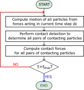
The schematic flowchart, which has to be followed in order to execute a DEM calculation [39] at each time step, is displayed in Figure 2.1a. Even if the algorithm looks to be straightforward to run and easy to implement, the computational cost is proportional to the number of discrete elements and to their shapes. Thus, simplified assumptions have been made in the mathematical models in order to reduce the computational efforts. The primary idealized factor in DEM simulations is the shape of particles which is considered as spheres to simplify the contact detection process, which is the most time consuming step in DEM simulations. Among diverse physical properties of individual particles in particulate materials, the shape and morphology play important roles in shear strength and flowability of the bulk. In order to improve this aspect several approaches have been utilized in DEM, such as, clumped spheres [40], polyhedral shapes [41], super-quadric function [42]. However, in order to obtain accurate results the computational cost may arise significantly. Another important step in DEM is to realistically simulate the physical impact between particles. This is usually approximated by defining spring and dashpots between contacting surfaces, as it is done in the linear-spring dash-pot models [43] or the Hertzian visco-elastic models. In the literature other contact models can be found, such as meso-scale models [35,44,45] or realistic contact models [46,47,48], which can provide a high accuracy both at the particle and bulk level, but valid only for the limited class of materials they are particularly designed for.
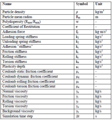
Moreover, for a proper understanding of a process and to study realistic behaviour through DEM simulations, the input parameters, listed in Figure 2.1b, play a vital role. The input parameters are often assumed without careful assessment or calibration which often leads to unrealistic behaviours and erroneous results. Designing of equipment or of a process route with an un-calibrated DEM model may lead to serious handling and processing operations such as segregations, unexpected wear, irregular density of products, flow blockages and etc. Thus, a correct definition of the input parameters by experimental characterization and/or calibration, using particle-level tests, directly affect the reliability of the final response at the bulk level. However, this might result in an extremely time and cost consuming procedure, that not always it is possible to perform for a lack of time and/or money.
In conclusion, DEM is a valid and useful numerical tool for research in the granular matter field and development of new contact models. However, the drawbacks aforementioned in the current section make the DEM still not an easy and limited tool to use in the engineering and industrial framework, mainly when real scale systems are under study.
| |
| (a) | |
| |
| (b) | |
| Figure 2.1: Dem algorithm (a), with the time instant and the time interval, and input parameters in DEM model (b). | |
2.2.2 The Smoothed Particle Hydrodynamics
Among the methods which serve as approximations of the strong of PDEs, the Smoothed Particle Hydrodynamics (SPH) [49,50] is one of the earliest particle methods in computational mechanics. It was initially designed for solving hydrodynamics problems [51,52], such as astrophysical applications [53,54,55]; later, SPH has been also applied to solid mechanics problems involving impact, penetration and large deformation of geomaterials [56,57,58,59] or compressible and incompressible flow problems [60,61]. The PDE is usually discretized by a specific collocation technique: the essence of the method is to choose a smooth kernel which not only smoothly discretized a PDE, but also furnishes an interpolant scheme on a set of moving particles. Even if the method is widely used by the computational mechanics community, it is well established in the literature that the SPH suffers of some pathologies such as tensile instability [62,63], lack of interpolation consistency [64,65], zero-energy mode [66] and difficulty in enforcing essential boundary condition [67,68]. To solve the aforementioned fundamental issues several improvements have been provided through the years. To mitigate the tensile instability and the zero-mode issues the stress point approach [63,69] has been proposed. To correct completeness, or consistency, closely related to convergence, the use of corrective kernels are considered; for instance Liu et al. [64] proposed new interpolants named the Reproducing Kernel Particle Method and many other approaches can be found in the literature [70,71,72] addressing this shortcoming. To enforce essential boundary conditions it is worth mentioning the contribute of Randles and Libersky [67], where the so-called ghost particle approach is proposed.
2.2.3 The Meshfree Galerkin Methods
The Meshfree Galerkin Methods, unlike the SPH, were mainly developed only in the early of 1990s. The first meshless methods appeared in the literature are represented by the Diffusive Element Method [73], where moving least square (MLS) interpolants [74] are employed, and the Reproducing Kernel Particle Method (RKPM) [64,75], defined in the attempt to provide a corrective SPH. Later, other techniques were proposed, such as the Element Free Galerkin Method (EFGM) [76], in which the MLS interpolants are for the first time used in a Galerkin procedure, or the Partition of Unity Method [77], where a partition of unity is taken and multiplied by any independent basis. Usually most meshfree interpolants do not satisfy the Kronecker delta property 1 and the impossibility of a correct imposition of the essential boundary conditions represents one of the principal bottleneck of these approaches. Some remedies for the enforcement of the EBCs are given by the Lagrange Multipliers and Penalty method [78], the Transformation method [79], the Boundary singular kernel method [74] and the Coupled finite element and particle approach [80]. Most Meshfree Galerkin Methods make use of background grid to locate the quadrature points to integrate the weak form. From this aspect some problems in terms of accuracy as well as invertibility of the stiffness matrix may arise, due to the arbitrariness in locating the Gauss quadrature points. If these points are not enough in a compact support or are not evenly distributed spurious modes may also occur. In order to completely eliminate quadrature points some approaches have been proposed in the literature, e.g., the one proposed by Chen et al. [81] based on a stabilized nodal integration method. Despite the typical drawbacks of Meshfree Galerkin Methods, e.g., the aforementioned issue of quadrature integration and the higher computation cost in comparison with standard FEM, during the last decades meshless methods have been increasingly used to solve applied mechanics problem due to some key advantages which distinguish them from other techniques. For instance to mention some of them, in these methods the connectivity changes with time as they do not have a fixed topological data structure, the accuracy can be controlled easily given a h-adaptivity procedure and the meshfree discretisation can provide accurate representation of geometric object. Initially, meshfree methods have been used to address the challenging field of computational fracture mechanics. In this regards, the EFGM and the Partition of Unity Methods have been applied to crack growth and propagation problems [82,83,84]. The great advantage of not using a remeshing procedure has been also exploited in the application of large deformation problems; in particular, it is worth mentioning the use of the RPKM to metal forming, extrusion [85] and soil mechanics problems [86,87]. Meshfree methods have been also extensively applied to simulation of strain localization problems [88] since meshfree interpolants can successfully reduce the mesh alignment sensitivity in the formation of the shear bands.
(1) Let us define the Lagrange polynomials of degree , . satisfy the Kronecker delta property if
|
|
(2.1) |
i.e., . With regards to the shape functions, these ones lack of the Kronecker delta property when the weight function associated with the nodal points is not zero at the location of nodal point of interest .
2.2.4 The Particle Finite Element Method
The Particle Finite Element Method (PFEM) is a particle method which falls under the category of mesh-based Galerkin approaches. In PFEM the domain is modelled using an Updated Lagrangian formulation and the continuum equations are solved by means of a FEM approach on the mesh built up from the underlying node, also called . The main feature of the method is based on the employment of a fast remeshing procedure to relieve the typical issue of high distortion of the mesh and a boundary recognition method, i.e., the alpha-shape technique [89], needed to define the free surfaces and the boundaries of the material domain. Given an initial mesh, the remeshing procedure can be used arbitrarily at every time step [90] or when the mesh starts affecting the accuracy of the numerical solution, as in the case of explicit formulations [91]. This Lagrangian technique was first developed for the simulation of free surface flows and breaking waves [92,93], and then successfully adapted for structural mechanics problems involving large deformations [94,95], for the simulation of viscoplastic materials [96,91,97,98,99,100], in geomechanics [101,102] and Fluid-Structure Interaction (FSI) applications [103,104,105]. Although the method has broad capabilities, some disadvantages come from the use of remeshing procedures [106,107]. In the practice, although possible, the application of PFEM in problems with elastic or elasto-plastic behaviour faces difficulties related to the storage of historical variables, since information on the integration points is not preserved and needs to be remapped at the moment of remeshing. Moreover the alpha-shape technique, and the remeshing itself, lead to intrinsic conservation problems related to the arbitrariness of the reconnection patterns [108]. Last but not least, the characteristics of the remeshing approach at the base of the PFEM make it very hard to parallelize, thus, limiting the possibility of the method in terms of computational efficiency.
2.2.5 The Particle Finite Element Method 2
A second generation of PFEM (PFEM2) has been recently introduced [109,110,111,112], which tries to repair to the shortcomings observed in the previous version. PFEM2 is a hybrid particle method, which exploits the combination of both the Eulerian and Lagrangian approaches, as in the Material Point Method. The method has been tested in the analysis of interaction between different materials, such as, incompressible multifluids and fluid-structure interaction [113], and simulation of landslides and granular flows problems [114]. This technique is based on the use of a set of Lagrangian particles, in order to track properties of the continuum, and by a fixed finite element mesh, employed for the solution of the governing equations. Moreover, a projection of the data between the two spaces is performed during the calculation of a time step in order to keep updated the kinematic information between the particles and the nodes of the Eulerian mesh. One of the main differences which distinguishes PFEM2 from the Material Point Method lies on the definition of Lagrangian particle itself. In the case of PFEM2, the particles represent material points without a fixed amount of mass; in order to guarantee a good particle distribution in the computational domain, the number of particle might change during the simulation time. These Lagrangian entities do not represent integration points, but are just used with the purpose of convecting all the historical material properties and kinematic information through the simulation. This feature makes PFEM2 particularly adapted for the modelling of incompressible fluids, with Newtonian and non-Newtonian rheology and FSI problems.
2.3 The Materal Point Method
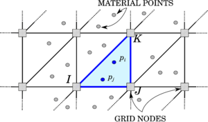
An alternative particle method proposed in the literature is represented by the Material Point Method (MPM) [115,28], which is object of study of this monograph. The Material Point Method (MPM) is a particle-based method, whose origin goes back to the paper of [116], where the particle-in-cell method (PIC), a technique for the solution of fluid flow problems, was proposed for the first time. Some decades after, in the works of [115,28], the PIC method is redefined within the solid mechanics framework, and after that, it is known to the computational community with the name of Material Point Method. MPM combines a Lagrangian description of the body under analysis, which is represented by a set of particles, the so-called material points, with the use of a computational mesh, named background grid, as can be observed in Figure 2.2.
|
| Figure 2.2: MPM. The shape functions on the material point are evaluated using FE shape function of element I-J-K. |
This distinctive feature allows one to track the deformation of the body and retrieve the history-dependent material information at each time instant of the simulation, without committing mapping information errors, typical of methods which make use of remeshing techniques. This makes the method particularly attractive for the solution of problems, characterized by very large deformations and by the use of complex constitutive laws [117,118]. For instance, the method has been extensively used for geotechnical problems [119,120,118] for its capabilities in tracking extremely large deformation while preserving material properties of the material points.
In the key works of Sulsky and co-workers [115,28], the MPM has been applied for the first time in the solid mechanics framework. Even if through the original MPM it was possible to solve complex problems involving, for instance, contact [121], interaction between different materials [122,123] and the use of history-dependent material laws [115], it was observed that the first version of MPM suffers from some intrinsic shortcomings. Indeed, due to the use of piece-wise linear shape functions, the latter are only locally defined and their gradients are discontinuous. This implies that a material point on the cell boundary would not be covered by the local shape functions defined within the respective cells around the particle. This would produce a noise in the numerical solution, which is called cell-crossing error. Recently, many improvements to the original MPM have been provided to alleviate the cell-crossing noise and to have a more efficient and algorithmically straightforward evaluation of grid node integrals in the weak formulation. The Generalized Interpolation Material Point method (GIMP) [124] represents the first attempt to provide an improved version of the original MPM. The essence of this method is based on the definition of a characteristic function which has to satisfy the partition of unity criterion, i.e.,
|
|
(2.2) |
The particle characteristic function defines the spatial volume occupied by the particle as
|
|
(2.3) |
where and are the current particle domain and the current domain occupied by the continuum, respectively. Moreover, since a material property can be approximated by its particle value as
|
|
(2.4) |
acts as a smoothing of the particle properties and it determines the smoothness of the spatial variation. The full version of GIMP requires integration over the current support of , which deforms and rotates according to the deformation of the background grid. To do that, a tracking of the particle shape is mandatory, but in a multi-dimensional problem this could be very difficult to accomplish. Thus, an alternative version of the GIMP is represented by the uniform GIMP (uGIMP), where shear deformation and rotation of the particles are neglected. The uGIMP assumes that the sizes of particles are fixed during the material deformation. In this way, the particle characteristic function, whose support may overlap or leave gaps for very large deformation, is no longer able to satisfy the partition of unity criterion, and, thus, the ability of computing rigid body motion is lost. Therefore, the uGIMP is unable to completely eliminate the cell-crossing error.
In the attempt to improve the issues left by the GIMP, the Convected Particle Domain Interpolation technique (CPDI) [125] is proposed. In the CPDI the particle has an initial parallelogram shape and a constant deformation gradient is assumed over the particle domain. This technique is a first-order accurate approximation of the particle domain . Even if in the CPDI a more accurate approximation of is obtained, the issues of overlaps and gaps are not overcome. Only with the second-order Convected Particle Domain Interpolation (CPDI2) [126], an enhanced CPDI, which provides a second-order approximation of the particle domain, these issues are totally corrected. It is also worth mentioning the Dual Domain Material Point Method (DDMPM) [127], an alternative technique which is able to definitely eliminate the cell-crossing error. Unlike the GIMP or CPDI, the DDMPM does not make use of particle characteristic functions and the issue of tracking the particle domain through the whole simulation is avoided. The essence of this technique relies on the use of modified gradient of the shape function, defined as follows
|
|
(2.5) |
where is the gradient of the shape function evaluated as in the original MPM, is the gradient from the node-based calculation as used in FLIP ( FLuid-Implicit Particle)[128].
Most MPM codes make use of explicit time integration, due to the ease of the formulation and implementation [115,129,130]. Explicit methods are preferable to solve transient problems, such as impact or blast, where high frequencies are excited in the system [131,132,121]. However, when only the low-frequency motion is of interest, the adoption of an implicit time scheme may reduce the computational cost in comparison to the employment of an explicit time scheme [133]. Some implicit versions of MPM can be found in the literature. For instance, Guilkey [134] exploits the similarities between MPM and FEM in an implicit solution strategy. Beuth [135] proposes an implicit MPM formulation for quasi-static problems using high order elements and a special integration procedure for partially filled boundary elements. Sanchez [136] presented an implicit MPM for quasi-static problems using a Jacobian free algorithm and in [137] a GIMP method is used together with an implicit formulation.
In order to assess the features of MPM, as reference for a comparison, a standard Lagrangian FEM is chosen. In Table 2.3, the two methods are compared and a list of differences is made, according to the basic formulation, computational efficiency and computational accuracy. It is observed that in the small deformation range the MPM has a lower accuracy and efficiency than a Lagrangian FEM. Nevertheless, the FEM procedure shows its advantageous use only in a narrow range of strain magnitude, established by a critical deformed configuration for which the element quality is seriously compromised, which may cause a drastic deterioration of accuracy or even the end of the computation. In this regard, it is evident that MPM finds its natural field of application in large deformation problems. However, it is important to highlight that an extra computational cost is expected in MPM compared to FEM. This is due to additional steps in the MPM algorithmic procedure, in order to be able to track the kinematic and historical variables through the deformation process, and to a number of material points higher than the number of Gauss points normally employed in a FEM simulation.
| STANDARD LAGRANGIAN FEM | MPM |
| BASIC FORMULATION | |
| Gauss quadrature | Particle quadrature |
| The Lagrangian computational mesh is attached to the continuum during the whole solution process | No fixed mesh connectivity is required |
| Higher accuracy and efficiency for small deformations | Lower accuracy and efficiency of the MPM for small deformations |
| For large deformations accuracy rapidly deteriorates and computational cost increases dramatically due to mesh distortion and the need for remeshing | It naturally deals with large deformation problems |
| Contact between different bodies can be modelled only by applying a contact technique | Unphysical material interpenetration and non-slip contact constraint are inherent in the MPM |
| COMPUTATIONAL EFFICIENCY | |
| Mass and momentum are carried by the mesh nodes and they are calculated only at the beginning of the analysis. Further Gauss points move according to the mesh such that it is not necessary to update their positions and velocities | Additional steps have to be performed such as mapping of particle info (mass and momentum) on the grid and the update of particle info at the end of the Lagrangian step |
| Less Gauss points per element | Minimum number of particles per element higher than number of Gauss points per element |
| In explicit time scheme, the critical time step decreases with the element deformation | In MPM the characteristic element length does not change, thus, the critical time step size in MPM is constant |
| COMPUTATIONAL ACCURACY | |
| The Gauss quadrature can integrate accurately the weak form | The particle quadrature is less accurate than the Gauss one for integrating the weak form |
| For large deformations, in order to avoid element entanglement, a remeshing technique has to be adopted. However, this can lead to conservation issues of mass, momentum and energy. Further, the remapping of material properties of history-dependent material will result in significative errors | The original MPM suffers from a cell crossing instability |
As earlier discussed, the MPM is a particle method, whose advantages are evident in applications at large strain and displacement regime. Moreover, the MPM is characterized by some features which make this technique able to overcome all the typical disadvantages of other particle methods, listed in the previous sections. MPM does not employ any kind of remeshing procedure, the calculation is performed always at a local level, allowing an easy adaptation of the code to parallel computation and a good conservation of the properties. A conservation of the mass is also guaranteed during the whole simulation time, as the total mass is distributed between the material points representing the volume of the entire continuum under study. A remapping of the state variables is avoided and the employment of complex time dependent constitutive laws can be used without committing any mapping error. In addition, since this technique is a grid-based method all the issues, related to the meshless methods, such as, lack of interpolation consistency and difficulties in enforcing the Essential Boundary conditions are avoided. Last but not least, MPM is a technique defined in the continuum mechanics framework, thus, it can be easily applied to real scale problems at a not prohibitive computational cost. Given the fulfillment of the aforementioned features, MPM represents a suitable choice for the solution of real scale large deformation problems and particularly attractive for the modelling of granular flow problems.
2.4 The Material Point Method in Kratos Multiphysics
In the current work, an implicit MPM is developed in the multi-disciplinary Finite Element codes framework Kratos Multiphysics [29,30,31]. Two formulations are investigated: a displacement-based [138] and a mixed displacement-pressure (u-p) [139,140] formulations, presented in Chapters 4 and 5, respectively. In both the numerical strategies, the original version of the MPM is implemented, i.e., a particle integration is adopted, where the particle mass is assumed to be concentrated only on one spatial point, the particle position. As earlier discussed, this may lead to the so-called cell-crossing error; however, it is demonstrated that GIMP method is not able to definitely fix this issue and only other more computationally expensive techniques, such as, the CPDI2 and the DDMPM can remarkably mitigate this inherent error. In this work, it is made the choice to focus on the capabilities of the method in the modelling of granular flows under large deformation and large displacement regime and to leave, as future work, the exploration and investigation of other versions of MPM, which can improve the accuracy of the numerical results. The MPM in Kratos Multiphysics is developed in an Updated Lagrangian finite deformation framework and the matrix system to be solved is built-up from taking into account the contribution of each material point, to be considered as integration point, as well. In the initialization of the solving process, the initial position of the material points is chosen to coincide with the Gauss points of a FE grid and the mass, which remains constant during the simulation, is equally distributed between the material points, falling, initially, in the same element. At each time step, the governing equations are solved on the computational nodes, while history dependent variables and material information are saved on the particles during the entire deformation process. Thus, in the MPM the material points shall be understood as the integration points of the calculation, each carrying information about the material and kinematic response. Each material point represents a computational element with one single integration point (the material point itself), whose connectivity is defined by the nodes of the elements in which it falls. In Figure 2.2, for instance, the case of the i-th material point, which falls in a triangular element with a connectivity of nodes and , is depicted. In the evaluation of the FEM integrals, the shape functions are evaluated at the material point location on the basis of the grid element the material point falls into (Figure 2.2). At the end of every time step, in order to prevent mesh distortion, the undeformed background grid is recovered, i.e., the nodal solution is deleted.
In what follows, the algorithm of MPM for an implicit time scheme discretization is presented in detail.
2.4.1 MPM Algorithm
Traditionally, the MPM algorithm is composed of three different phases [28], as graphically represented in Figure 2.3 and below described:
- Initialization phase (Fig.2.3a): at the beginning of the time step the connectivity is defined for each material points and the initial conditions on the FE grid nodes are created by means of a projection of material points information obtained at the previous time step ;
- UL-FEM calculation phase (Fig.2.3b): the local elemental matrix, represented by the left-hand-side () and the local elemental force vector, constituted by the right-hand-side () are evaluated in the current configuration according to the formulation presented in Chapters 4 and 5; the global matrix and the global vector are obtained by assembling the local contributions of each material point, as in a classical FEM approach, and, finally, the solution system is iteratively solved. During the iterative procedure, the nodes are allowed to move, accordingly to the nodal solution, and the material points do not change their local position within the geometrical element until the solution has reached convergence;
- Convective phase (Fig.2.3c): during the third and last phase the nodal information at time are interpolated back to the material points. The position of the material points is updated and, in order to prevent mesh distortion, the undeformed FE grid is recovered.
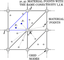
|
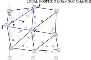
|
| (a) Initialization phase | (b) Updated Lagrangian FEM phase |
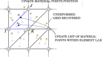
| |
| (c) Convective phase | |
| Figure 2.3: MPM phases. | |
Many features of the MPM are connected to the Finite Element Method [115]. Indeed, phase b coincides with the calculation step of a standard non-linear FE code, while phases a and c define the MPM features. At the beginning of each time step (), during phase a, the degrees of freedom and the variables on the nodes of the fixed mesh are defined gathering the information from the material points (Figure 2.3a).
For the sake of clarity, hereinafter, and subscripts are used to refer to variables attributed to material points and computational nodes, respectively, while superscript refers to the time instance in which the variable is defined. The momentum and inertia on the material points, which are expressed as functions of mass , velocity and acceleration
|
|
(2.6) |
|
|
(2.7) |
are projected on the background grid by evaluating in a first step, the global values of mass , momentum and inertia on node as described in Algorithm 2.1.
Once , and are obtained, it is possible to compute the values of nodal velocity and nodal acceleration of the previous time step as
|
|
(2.8) |
|
|
(2.9) |
It is worth mentioning that, the initial nodal conditions are evaluated at each time step using material point information in order to have initial values even on grid elements empty at the previous time step ().
The MPM makes use of a predictor/corrector procedure, based on the Newmark integration scheme. The prediction of the nodal displacement, velocity and acceleration reads
|
|
(2.10) |
|
|
(2.11) |
|
|
(2.12) |
where the upper-left side index indicates the iteration counter, while the upper-right index the time step. and are the Newmark's coefficients equal to 0.5 and 0.25, respectively.
Once the nodal velocity and acceleration are predicted (Equations 2.10-2.12), the system of linearised governing equations is formulated, as in classic FEM, and the local matrix and the residual are evaluated and assembled, respectively (phase b, Figure 2.3b).
The solution in terms of increment of nodal displacement is found iteratively solving the residual-based system. Once the solution is obtained, a correction of the nodal increment of displacement is performed
|
|
(2.13) |
Velocity and acceleration are corrected according to Equations 2.11 and 2.12, respectively. This procedure has to be repeated until convergence is reached.
Unlike a FEM code, the nodal information is available only during the calculation of a time step: at the beginning of each time step a reset of all the nodal information is performed and the accumulated displacement information is deleted. The computational mesh is allowed to deform only during the iterative procedure of a time step, avoiding the typical element tangling of a standard FEM. When convergence is achieved, the position of the nodes is restored to the original one (phase c, Figure 2.3c). Before restoring the undeformed configuration of the FE grid, the solution in terms of nodal displacement, velocity and acceleration is interpolated on the material points, as
|
|
(2.14) |
|
|
(2.15) |
|
|
(2.16) |
where is the total number of nodes per geometrical element, are the local coordinates of material point and is the shape function evaluated at the position of the material point , relative to node .
Finally the current position of the material points is updated as
|
|
(2.17) |
The details of the MPM algorithm are presented in Algorithm 2.1.
|
(we will use ), Material DATA: E, , | ||||||||||||||||||||||||
| Initial data on material points: , , , and | ||||||||||||||||||||||||
| Initial data on nodes: NONE - everything is discarded in the initialization phase | ||||||||||||||||||||||||
| OUTPUT of calculations: | ||||||||||||||||||||||||
| ||||||||||||||||||||||||
|
Algorithm. 2.1 MPM algorithm. |
2.5 The Galerkin Meshless Method
In Section 2.3 the Material Point Method and its state of the art is presented. Different versions of the method, proposed with the attempt to overcome the cell-crossing error issue, are discussed. An alternative to the approaches aforementioned, such as GIMP, CPDI and DDMPM, is represented by the Galerkin Meshless Method (GMM) [141]. The GMM can be seen as the MPM, where the Eulerian background grid is replaced by a Lagrangian one, defined by a cloud of nodes. In GMM, the material points move together with the computational nodes and the shape functions are evaluated once the surrounding cloud of nodes is defined (Figure 2.4a). In this case, unlike MPM, the nodes preserve their history through the whole simulation, as in FEM. GMM is a continuum method and it does not make use of a remeshing technique which gives all the advantages of MPM, previously discussed, such as, local level calculation, good conservation properties and an easy adaptation to parallel computing. The GMM is a truly meshless method, based on a Galerkin formulation. Unlike other methods, such as, the Element-Free Galerkin Method [76] or the Reproducing Kernel Particle Method [64], this technique does not need element connectivity for integration or interpolation purposes. However, as it belongs to the class of techniques described in Section 2.2.3, it may suffer from the drawbacks which typically affects all the meshless methods (e.g. tension instability, difficulty in enforcing the Essential Boundary Conditions (EBCs), lack of interpolation consistency, etc.). Apart from these shortcomings, GMM with MPM might represent a suitable choice for the solution of real scale large deformation problems and a comparison within a unified framework would be beneficial for an objective evaluation of the capabilities of each method.
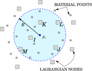
|
| Figure 2.4: GMM. The shape functions on the material point are evaluated using the information on the nodes sufficiently closed to the material point itself. |
2.6 The Galerkin Meshless Method in Kratos Multiphysics
In this section the Galerkin Meshless Method, implemented in Kratos Multiphysics, is described. The algorithm presented in [141] to simulate fluid-structure interaction problems is taken as a starting point and adapted to the simulation of deformable solids [138].
As explained in Section 2.5, the GMM is a truly meshless method and it can be seen as the application of the MPM idea extended to the case in which both the nodes and the material points behave as purely Lagrangian through the whole analysis. Thus, it is relatively easy to enforce conservation properties at the integration points, while also maintaining the history of nodal results during all the simulation time, provided that a reliable technique is chosen for the computation of the meshless shape functions. The difficulty is, hence, moved to the construction of such an effective meshless base, which is addressed in Section 2.6.2. In what follows, the algorithm used for the implementation of the GMM in Kratos Multiphysics is described. Differences and analogies with the MPM algorithm procedure are highlighted. Moreover, the construction of effective meshless intepolants is discussed in Section 2.6.2, where two techniques are presented: the Moving Least Square (MLS) technique and the Local Max-Ent (LME) method. Further, in Chapter 4 a comparison between the MPM and the GMM is performed through some benchmark tests and an assessment in terms of computational cost, accuracy and robustness is provided.
2.6.1 GMM Algorithm
The GMM algorithm is based on three principal steps (see Figure 2.5).
- Initialization phase (Fig.2.5a): this is the step which mostly distinguishes GMM from MPM. During this phase the connectivity of each integration point (i.e., each material point) is computed as the "cloud of nodes", centred on the material point, and obtained by a search-in-radius. Such a cloud is then employed for the calculation of the shape functions. Unlike MPM, the Newmark prediction is performed by using the nodal information of the previous time step, as in FEM. Once and are suitably defined, MPM and GMM essentially coincide in the following steps;
- UL-FEM calculation phase (Fig.2.5b): the local matrix, represented by the left-hand-side () and the local vector, constituted by the right-hand-side () are evaluated in the current configuration according to the formulation presented in Chapter 4; the global matrix and the global vector are obtained by assembling the local contributions of each material point and, finally, the system is iteratively solved. During the iterative procedure, the nodes are allowed to move, accordingly to the nodal solution, and the material points do not change their local position within the geometrical element until the solution has reached convergence;
- Convective phase (Fig.2.5c): during the third and last phase the nodal information at time are interpolated back to the material points. The position of the material points is updated. Unlike MPM, the nodal information are not deleted, but used as initial conditions in the next time step.
The details of the GMM algorithm are presented in Algorithm 2.2.
|
|
| (a) Initialization phase | (b) Updated Lagrangian FEM phase |
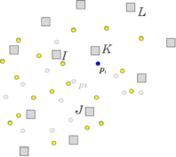
| |
| (c) Convective phase | |
| Figure 2.5: GMM phases. | |
|
Material DATA: E, , | ||
| Initial data on material points: , , and | ||
| Initial data on nodes: | ||
| OUTPUT of calculations: | ||
| ||
|
Algorithm. 2.2 GMM algorithm. |
2.6.2 Calculation of GMM shape functions
While the computation of the shape functions is trivial for the standard MPM (as in FEM), thanks to the presence of a background grid (Figure 2.2), the evaluation of the shape functions in GMM is more complex. From a technical point of view, GMM is based on a conceptually simple operation: given an arbitrary position in space (which will, in the practice, coincide with the position of the material point) and a search radius , one may find all of the Nodes such that . Given such a cloud of nodes, one may then compute, at the position , the shape functions (together with their gradients), such that, a given function , whose nodal value is , can be interpolated at the position as (Figure 2.4a).
However, in order to construct a convergent solution, some guarantees must be provided by the shape functions. In particular, they shall comply with the Partition of Unity (PU) property, as a very minimum at all of the positions at which the shape functions are evaluated. A number of shape functions exist complying with such property [142,143,33]. Among the available options, two appealing class of meshless functions are considered in this work: the first choice is constituted by the so called Moving Least Square (MLS) method and the second one represented by the Local Maximum Entropy (LME) technique.
The first technique is based on the MLS approach, first introduced by Lancaster [74] and Belytschko [76,143]. The MLS-approximation fulfils the reproducing conditions by construction, so no corrections are needed. The fundamental principle of MLS approximants is based on a weighted least square fitting of a target solution, sampled at a given, possibly randomly distributed, set of points, via a function of the type
|
|
(2.18) |
where the coordinates are to be understood as relative to the sampling position.
The reconstruction of a continuous function can be obtained considering the data be located at points and an arbitrary, smooth and compactly supported, weight function , such that the fall within the support of . Assuming now that the reconstructed function () is computed as
|
|
(2.19) |
the fitting to is done by minimizing the error function , defined as
|
|
(2.20) |
where .
This allows defining a set of approximating shape functions such that
|
|
(2.21) |
where
|
|
(2.22) |
with defined as
|
|
(2.23) |
It can be readily verified that the shape functions are able to reproduce exactly a polynomial up to the order used in the construction. This fact can also be used to prove compliance to the partition of unity property. Namely, if one assumes and substitutes into Equation 2.21 then
|
|
(2.24) |
Hence, considering the special case of a constant polynomial , or of a linear variation in , we obtain respectively
|
|
(2.25) |
A similar reasoning also gives
|
|
(2.26) |
thus proving the compliance with the PU property.
However, MLS shape functions are not able to guarantee the Kronecker delta property at the nodes. This implies that two nodal shape functions may be simultaneously non zero at a given nodal position. This has practical implications at the moment of imposing Dirichlet Boundary conditions, namely, in order to impose at a given point on the Dirichlet boundary , one must impose that , which constitutes a classical multipoint constraint [144].
Interestingly, the choice of different shape functions could ease this particular problem. An appealing choice could be the use of LME approximants, which guarantees complying with a weak Kronecker delta property until the cloud of nodes is represented by a convex hull.
The LME technique is based on the evaluation of the local max-ent approximants [145], which represents the solution that exhibits a (Pareto) compromise between competing objectives: the principle of max-ent subject to the constraints:
|
|
(2.27) |
and the objective function interpreted as a measure of locality of the shape functions of the Delaunay triangulation
|
|
(2.28) |
The solution to the problem can be found minimizing subjected to the usual constrains. The optimization problem takes the form
|
|
(2.29) |
with representing a non-negative locality coefficient, where is a dimensionless parameter and is a measure of nodal spacing. The value of is always chosen in a range between , relative to spread-out meshfree shape functions, and , relative to linear finite elements basis functions. Unlike MLS approximants, the LME basis functions possess the weak Kronecker delta property at the boundary of the convex hull of the nodes and they are function of in . However, the computation of the LME approximation scheme is more onerous than MLS basis functions, as the problem described by Equation 2.29 is a convex problem.
3 Constitutive Models
As explained in the previous Chapters, granular material can be modelled by continuum approach on a macroscopic scale. In the continuum approach, the macroscopic behaviour of granular flow is described by the balance equations (introduced in Chapter 4) facilitated with boundary conditions and constitutive laws. These latter ones characterize the relation between the stress and strain, thus, defining the behaviour of the material. In this Chapter, the constitutive models employed in this monograph for verification, validation and application of the MPM strategy are presented and their numerical implementation is explained.
The irreducible and mixed formulations, presented and verified in Chapters 4 and 5, respectively, are written in an Updated Lagrangian framework, e.g, the last known configuration is considered to be the reference one, and are valid under the hypothesis of large deformations, since the strain information, used for the evaluation of the material response, is represented by the total deformation gradient and not by the symmetric gradient of displacement . In this monograph, homogeneous isotropic elasic and elasto-plastic materials are considered. More specifically, a hyperelastic Neo-Hookean, a hyperelastic-plastic J2 and Mohr-Coulomb plastic laws have been implemented in the framework of MPM and they are presented in Sections 3.1, 3.2 and 3.3.
3.1 Hyperelastic law
The first constitutive law to be presented is an elastic law under finite strain regime. In this regard, in the current work a hyperelastic material is considered. Typically, these models are suitable to describe the behaviour of engineering materials which can undergo deformation of several times their initial configuration, such as, rubber-like solids, elastomers, sponges and other soft flexible materials. Hyperelastic materials are non-dissipative and their state of stress solely depends on the current deformation, as the Cauchy elastic models, and do not depend on the path of deformation. For this reason, in this case it is possible to derive the stress-strain relation from a specific strain energy function
|
|
(3.1) |
which relates the specific strain energy to the total deformation gradient as unique state variable, since dissipative related state variables can be neglected and the assumption of isothermal processes is made [146]. As stated in [146], any constitutive law must satisfy the axioms of thermodynamic determinism, material objectivity and material symmetry. The compliance of the first axiom implies the stress constitutive equation in terms of the first Piola-Kirchhoff stress tensor
|
|
(3.2) |
Accordingly, the stress constitutive relation can be expressed also by the Kirchhoff stress tensor
|
|
(3.3) |
which for a hyperelastic material is given by
|
|
(3.4) |
and the Cauchy stress tensor,
|
|
(3.5) |
where .
In order to comply with the second axiom, the specific strain energy function has to be invariant under changes in the observer. This can be expressed by the following equation
|
|
(3.6) |
which has to be valid for any rotation tensor . If we consider with the rotation obtained from the polar decomposition , the following identity is obtained
|
|
(3.7) |
Thus, the material objectivity or frame invariance implies that depends on solely through the right stretch tensor and in an equivalent way, can be expressed as a function of the right Cauchy-Green strain tensor :
|
|
(3.8) |
The stress constitutive equations in terms of , and can be expressed as
|
|
(3.9) |
|
|
(3.10) |
and,
|
|
(3.11) |
where the definition of is used. The specific strain energy function has to be further constrained by considering the third and last axiom of material symmetry. With a focus on material isotropy, must satisfy
|
|
(3.12) |
for all rotations . By choosing , it is established that
|
|
(3.13) |
which states that the specific strain energy function of an isotropic hyperelastic material must depend only on through the left stretch tensor . In an equivalent way, can also be a function of the left Cauchy-Green strain tensor as follows
|
|
(3.14) |
By considering both the axiom of frame invariance and material symmetry it implies that
|
|
(3.15) |
The hyperelastic law, considered in the current work, is a Neo-Hookean model, of the form
|
|
(3.16) |
with dependence only on the first invariant of , , which exhibits the following specific strain energy function [147]
|
|
(3.17) |
where and are the Lamé constants.
According to Equation 3.9, it is known the stress constitutive relation in terms of the first Piola-Kirchhoff stress tensor and, thus, also in terms of the second Piola-Kirchhoff stress tensor
|
|
(3.18) |
and the Kirchhoff stress tensor
|
|
(3.19) |
In order to derive the strain energy function of Equation 3.17 with respect to , the following expression needs to be solved
|
|
(3.20) |
By using these identities
|
|
(3.21) |
|
|
(3.22) |
and substituting them into the Equation 3.20, the final expression is obtained
|
|
(3.23) |
By considering the result of Equation 3.23, and substituting it in the expression of Equation 3.19, the Kirchhoff stress tensor reads
|
|
(3.24) |
which, after reminding the definition of the left Cauchy-Green strain tensor and the identity , the final expression reads
|
|
(3.25) |
where denotes the symmetric second order unit tensor.
As shown in Chapter 4, where the linearisation of the weak form is derived, a rate form of the constitutive equation is needed, and it can be obtained by taking the material derivative of the stress tensor [148]
|
|
(3.26) |
where, with , it is denoted the tangent modulus. The push-forward operation of Equation 3.26, , yields to the Lie derivative of in compact form
|
|
(3.27) |
After expressing the rate of as
|
|
(3.28) |
with the symmetrical spatial velocity gradient, defined as
|
|
(3.29) |
and , the Lie derivative can be expressed as
|
|
(3.30) |
where denotes the spatial incremental constitutive tensor. In order to define , the second derivative of with respect to , , has to be computed. By recovering Equation 3.23, it can be written as
|
|
(3.31) |
The derivative of follows from the rule which is valid for any second order tensor , which, in Cartesian components, can be expressed as
|
|
(3.32) |
Since is a symmetric tensor, only the symmetrical part is needed. This latter is given by the fourth order tensor defined in component form as
|
|
(3.33) |
According to Equations 3.21 and 3.33, it is possible to write again the expression of as:
|
|
(3.34) |
By performing a push-forward operation of this last expression, which defines the material tangent modulus (see Equation 3.26), the spatial incremental constitutive tensor is obtained
|
|
(3.35) |
with the fourth order symmetric identity tensor.
The spatial counterparts and of the fourth-order tensors and , have been evaluated through the push-forward operation:
|
|
(3.36) |
and
|
|
(3.37) |
In the case of nearly-incompressible materials, the numerical treatment is not trivial. With regard to the finite element analysis, as it is addressed in Chapter 5, the use of mixed finite element formulations is required where the mean stress is considered as an additional primary variable, together with the displacements. In the context of the specific strain energy function and the stress constitutive relation, the isochoric/volumetric split permits to treat in a different way the incompressible part. As follows, the split of the total deformation gradient is exploited
|
|
(3.38) |
and the expression of the volumetric and deviatoric terms respectively read
|
|
(3.39) |
|
|
(3.40) |
Accordingly, it is possible to define the deviatoric left Cauchy-Green strain tensor as
|
|
(3.41) |
and its first principal invariant
|
|
(3.42) |
With this last expression at hand, the specific strain energy function of a Neo-Hookean model is written as
|
|
(3.43) |
with representing the bulk modulus and the volumetric part of dependent on .
It is possible to find the expression of the Kirchhoff stress tensor by using Equation 3.19, which in the case of is derived:
|
|
(3.44) |
where is the fourth-order deviatoric projector tensor, the volume-preserving part of and the quantity , the only contribution to the volumetric part of , which in the case of a nearly-incompressible material is represented by the mean stress primary variable, as addressed in Chapter 5.
As it was previously done, in order to find the expression of the spatial incremental constitutive tensor , given by the sum of the volumetric and deviatoric contribution
|
|
(3.45) |
the second derivative of ,
|
|
(3.46) |
needs to be computed. The first addend of Equation 3.46 refers to the volumetric component and the second addend to the deviatoric component of the second derivative of . With regards to the first term, by performing the derivative with respect to leads to
|
|
(3.47) |
With respect to the deviatoric term of Equation 3.46, it is possible to derive it, by firstly rewriting it as
|
|
(3.48) |
and, then, by deriving with respect to
|
|
(3.49) |
By substituting the results of Equations 3.47 and 3.49 in the definition of
|
|
(3.50) |
the final expressions of the volumetric and deviatoric spatial incremental constitutive tensors are obtained
|
|
(3.51) |
|
|
(3.52) |
For the sake of clarity, Equations 3.36 and 3.37 are used in the push forward operation.
3.2 Hyperelastic - J₂ plastic law
In this section a hyperelastic - metal plastic law in finite strains regime is presented. In this context, the main hypothesis, on which the elastoplastic constitutive framework is based, is represented by the notion of the multiplicative decomposition of the total deformation gradient in an elastic and plastic component of the form
|
|
(3.53) |
This theory, introduced for the first time in [149,150], lies on the concept of a local intermediate stress-free configuration defined by the plastic total deformation gradient , which can be recovered by performing a purely elastic loading from the fully deformed configuration. As pointed out in [151], by formulating the plastic flow theory based on the concept of elastic-plastic multiplicative decomposition of , some features can be observed. The stress-strain relation derives from the specific strain energy function, decoupled into its volumetric and deviatoric parts and the integration algorithm reduces to the radial return mapping in which the elastic predictor is computed through the elastic stress-strain relation. In addition to that, as in the infinitesimal theory, it is possible to linearise the algorithm which allows to define the algorithmic tangent elastoplastic moduli in a closed-form. In the case that the plastic flow does not take place, the solution of finite elasticity is recovered and the procedure presented in Section 3.1 is valid. In this section, the equations which are used to derive the algorithmic procedure are presented under the hypothesis of isotropic stress response and isochoric plastic flow, i.e., .
The first equation to be introduced is the specific strain energy function, from which it is possible to derive the expression of the stress tensor. As previously discussed in Section 3.1, according to the axioms of thermodynamic determinism, material objectivity, material symmetry and the aforementioned notion of local stress-free configuration, the following specific strain energy function with uncoupled volumetric ( and deviatoric () part is considered
|
|
(3.54) |
with being the volume preserving part of the elastic right Cauchy-Green strain tensor. According to Equation 3.44, the elastic Kirchhoff stress tensor is derived as
|
|
(3.55) |
where is the volume preserving part of .
Once defined the stored energy function of Equation 3.54, it is necessary to introduce the yield condition, which is characteristic of the plastic theory; the classical Mises-Huber yield condition in terms of , graphically represented in Figure 3.1, can be expressed as
|
|
(3.56) |
with being the flow stress, the isotropic hardening and the hardening parameter. The last governing equation, which makes the plastic problem determined, is given by the fundamental form of the corresponding associative flow rule, which can be derived uniquely by satisfying the principle of the maximum dissipation [152]. As shown in [153,154], the associative flow rule in strain space reads
|
|
(3.57) |
|
|
| (a) | (b) |
| Figure 3.1: model in the principal stress space (a) and in plane (b) | |
where is the volume preserving part of the plastic right Cauchy-Green deformation tensor , is the plastic multiplier, is the unit vector of . In order to complete the formulation of the model, it is assumed that the parameter , as in the linear theory, is governed by a rate equation [151], where is subjected to the standard Kuhn-Tucker loading/unloading condition:
|
|
(3.58) |
and consistency condition
|
|
(3.59) |
The algorithmic procedure to be established in order to solve the plastic problem has to respect the material frame indifference principle. This can be accomplished by defining the discrete form of the evolution equation (see Equation 3.57) in material description. Accordingly, a time stepping algorithm is conducted by applying a backward Euler difference scheme on Equation 3.57:
|
|
(3.60) |
and by operating a push-forward transformation it is possible to recover the spatial form of the discrete spatial evolution equation through some useful and fundamental steps, such as
|
|
(3.61) |
|
|
(3.62) |
|
|
(3.63) |
where in Equation 3.62, the relation and the results of Equation 3.61 are used. By the use of the expressions earlier derived, the spatial form of Equation 3.60 is
|
|
(3.64) |
With the evolution equation written in spatial configuration, the yield condition and the definition of the Kirchhoff stress tensor it is possible to define the return mapping algorithm, through which the plastic problem is solved in the time interval . Let , , and the configuration be known data at time and the incremental displacement of the configuration , , at time used to defined the incremental deformation gradient which can be evaluated as . In order to compute the elasto-plastic response, a trial elastic state is defined where no plastic flow takes place. Through this assumption, the intermediate configuration remains unchanged, i.e.:
|
|
(3.65) |
which, by a push-forward transformation, corresponds to the spatial form:
|
|
(3.66) |
According to Equation 3.66, the trial state of stress is defined as
|
|
(3.67) |
and the discrete governing equations are written as
|
|
(3.68) |
|
|
(3.69) |
|
|
(3.70) |
By exploiting the Kuhn-Tucker condition in discrete form of Equation 3.70, two cases might be encountered. The first one, it is identified with the case the yield condition :
|
|
(3.71) |
then, the condition is directly satisfied and no plastic flow takes place, leading to a completely elastic response. In the second alternative case, where the yield condition , it is clear that can not be admitted and, according to Equation 3.68, leading to the condition of . Thus, in this case the radial return mapping has to be performed. By considering Equation 3.68 and applying the trace operator to it, it is immediately demonstrated that
|
|
(3.72) |
since . By substituting the expression of Equation 3.72 in Equation 3.68 it is found that
|
|
(3.73) |
which used for the definition of the deviatoric part of leads to
|
|
(3.74) |
By considering the expression , Equation 3.74 can be rewritten as
|
|
(3.75) |
with . From this last equation it is deduced that
|
|
(3.76) |
along with
|
|
(3.77) |
Thus, it is possible to rewrite the yield condition as
|
|
(3.78) |
and, finally, the unknown is determined
|
|
(3.79) |
which is used for the determination of and (see Equations 3.73 and 3.74, respectively). The procedure defined above is able to guarantee the preservation of the material frame indifference framework and it results in an extension to finite strains of the classical radial return mapping method of infinitesimal plasticity. The governing equations have been derived and the algorithmic procedure to be followed step-by-step is described in Algorithm 3.1.
|
Initial data on material points: , | |||||
| OUTPUT of calculations: , | |||||
| |||||
|
Algorithm. 3.1 Return Mapping algorithm. |
Finally, the closed form expression for the algorithmic elasto-plastic moduli is derived through the linearisation of the Kirchhoff stress tensor
|
|
(3.80) |
According to the definition of the tangent modulus in current configuration
|
|
(3.81) |
where denotes the metric tensor in the current configuration, the expression of in the context of the Hyperelastic- plastic law reads
|
|
(3.82) |
It is deduced that the first term of Equation 3.82 is given by the sum of Equations 3.51 and 3.52 and it reads
|
|
(3.83) |
In what follows, the derivation of the three last terms is presented. By rewriting Equation 3.79 as
|
|
(3.84) |
and deriving it with respect to , the derivative is obtained
|
|
(3.85) |
The derivative is solved by firstly rewriting it in reference configuration with the use of Equation 3.63 as
|
|
(3.86) |
and, then, by performing a push-forward transformation with , the derivative in current configuration is obtained
|
|
(3.87) |
The derivative is solved by introducing the following equation
|
|
(3.88) |
where and the derivative , according to [153], is defined as
|
|
(3.89) |
By substituting this last equation in 3.88, the final expression is obtained
|
|
(3.90) |
Having defined Equations 3.87 and 3.90, it is possible to write again Equation 3.85 as
|
|
(3.91) |
The last derivative to be solved is
|
|
(3.92) |
By substituting the expressions of Equations 3.87, 3.91 and 3.92 in Equation 3.82, the spatial constitutive tensor is finally obtained
|
|
(3.93) |
where the coefficients and are expressed as
|
|
(3.94) |
|
|
(3.95) |
|
|
(3.96) |
|
|
(3.97) |
and as in Equations 3.45 and 3.52, respectively.
When the use of a mixed formulation, with mean stress () and displacements () as primary variables, might be required, the reader has to refer to Equation 3.44 for the definition of the Kirchhoff stress tensor and to Equation 3.93 for the definition of the spatial constitutive tensor, keeping in mind that its volumetric part, , is obtained as prescribed by Equation 3.51.
3.3 Hyperelastic - Mohr-Coulomb plastic law
The plastic law, presented in the previous section, is based on the theory which works fine for the modelling of plastic behaviour of metals. As it can be noted, this kind of theory is pressure insensitive since the yield limit does not depend on the mean stress, also graphically represented by Figure 3.1. For materials, such as soils and other granular materials, whose behaviour is pressure-dependent, the employment of the plastic law, presented in Section 3.2, might be inappropriate. In this regard, one of the most used plastic model in geotechnical engineering is the Mohr-Coulomb strength theory. This constitutive law is a phenomenological model, based on the fundamental assumption that the macroscopic plastic behaviour is the result of the microscopic mechanism of friction sliding between the single grains which compose the bulk. This concept is expressed by one of the most important failure criteria proposed by Coulomb in 1776
|
|
(3.98) |
which states that the plastic flow starts when the state of stress on a specific plane exceeds the shear strength () which is a function of the normal stress , the material constants of cohesion and internal friction angle . By using the Mohr plane representation, where it is possible to visualize the shear stresses as function of the normal stresses, the Coulomb's failure criterion is shown in Figure 3.2.

|
| Figure 3.2: Coulomb's failure criterion in Mohr's plane representation |
According to this stress representation, Equation 3.98 can be seen as a failure envelope, which can be experimentally determined: the failure occurs when the Mohr's circle is just tangent to the failure envelope.
In this Section, a Mohr-Coulomb plastic law for finite strains is presented. For the derivation of the formulas which are the expressions of the stress return and elasto-plastic moduli, the theory presented by Simo in [155,156] is exploited. In these works, the main idea lies on modelling the elastic response by the use of principal stresses, which allows to extend the use of a small strain return mapping in stress space to the finite deformation regime. In Appendix A, the plastic flow rule within the multiplicative plastic framework is presented and the form in terms of Hencky strains is derived. According to this simplification, the following uncoupled form of the specific strain energy function is assumed
|
|
(3.99) |
quadratic in the principal Hencky strains , defined as
|
|
(3.100) |
with the eigenvalues of the left Cauchy–Green deformation tensor , which can be calculated according to its spectral decomposition
|
|
(3.101) |
where are the eigenbases associated with . If an isotropic elastic response is assumed, by defining the spectral decomposition of the Kirchhoff stress tensor as
|
|
(3.102) |
it can be observed that the eigenbasis of Equation 3.101 are the same of those of Equation 3.102.
With the specific strain energy function of Equation 3.99 and the aforementioned assumption of isotropy, the stress-strain relation in principal axes takes the form
|
|
(3.103) |
with being the Hencky elastic tensor.
As depicted in Figure 3.3, the Mohr-Coulomb criterion comprises six planes in principal stress space, forming six corners and a common vertex on the tension side of the hydrostatic axis.
|
|
| (a) | (b) |
| Figure 3.3: Mohr Coulomb model in the principal stress space (a) and in plane (b) | |
If the principal stresses are rearranged as
|
|
(3.104) |
the stresses are returned to only one of the six faces, the primary yield plane.
Following the reordering of principal stresses as described by Equation 3.104, the yield function and the plastic potential, in the case of Mohr-Coulomb plasticity, are respectively written as
|
|
(3.105) |
|
|
(3.106) |
where is the angle of internal friction, the cohesion and the dilation angle. The expressions of Equations 3.105 and 3.106 in the principal stress space are represented by planes and, accordingly, they can be rewritten as
|
|
(3.107) |
|
|
(3.108) |
where and are the gradients, and the constants and are respectively defined as
|
|
(3.109) |
|
|
(3.110) |
3.3.1 The stress regions
In the case of the Mohr-Coulomb plastic law, four types of stress returns and constitutive matrices are possible.In Figure 3.4a the stress regions are shown: return to a yield plane (with condition of ), to the line which corresponds to triaxial compression (), to the line which corresponds to triaxial tension () and to the apex point (point A). In order to be able to know to which region to apply the return, boundary planes between these regions need to be defined. In the case of a linear yield criterion, boundary planes in the principal stress space are planes (Figure 3.4b) and the solution of the problem is found by simply applying geometric arguments.
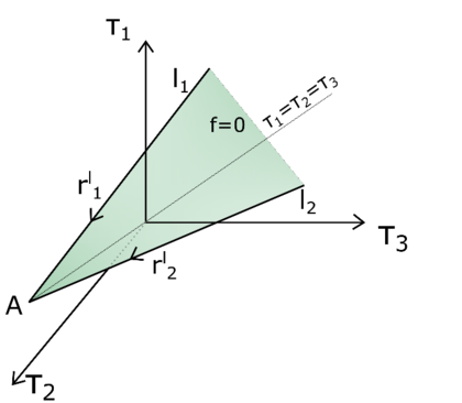
|
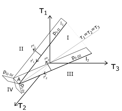
|
| (a) | (b) |
| Figure 3.4: Stress regions (a) and boundary planes (b) in the principal stress space | |
By using the definition of a plane in the principal stress space
|
|
(3.111) |
where is the normal to the plane and a stress point laying on the plane, and are expressed as
|
|
(3.112) |
|
|
(3.113) |
with
|
|
(3.114) |
and
|
|
(3.115) |
the vectors direction of lines and , and the vectors direction of the plastic corrector.
By using geometric arguments, it is possible to identify the four stress regions without defining the planes and . For instance, by considering the parametric equation of a line in the principal stress space
|
|
(3.116) |
where is a parameter with unit of stress and a stress point on the line, the parametric equations of lines and are
|
|
(3.117) |
|
|
(3.118) |
where parameters and are defined in a way that at the apex point ; thus, when the condition and are both satisfied the predictor stress falls in Region IV. Below, in Table 3.1 the conditions, which determine the stress regions and their corresponding return mapping, are listed.
| Conditions | Region | Type of return |
| and | I | |
| and | II | |
| and | III | |
| and | IV |
3.3.2 Stress update in principal stress space
In a general three-dimensional framework the development of the return mapping derivation and implementation in presence of singularities may result tedious. However, if isotropic yield criteria are considered, it is possible to reduce the dimension of the problem from six to three. Further, by taking advantage of considering an isotropic linear yield criterion and a perfect plastic law, for the implementation of the implicit integration scheme in principal stress space, the theory presented in [157] is followed. In this work, an efficient return algorithm, based on geometric arguments, is presented for infinitesimal deformation; as previously mentioned, if the specific strain energy function of Equation 3.99 is employed, the algorithmic procedure of [157] can be extended also to the case of finite strains in a straightforward way, as addressed in Appendix A. In the following, the stress update formulas and elasto-plastic tangent tensor are presented for each type of return. These expressions are, then, used in Algorithm 3.2 where the algorithmic procedure is described in the framework of a finite strain plastic model.
3.3.2.1 Return to a plane
In this respect, the evolution equation in finite strains in terms of Hencky strains, derived in Appendix A, is as follows
|
|
(3.119) |
In addition, in order to obtain the expressions for the return to the yield surface, the following condition is considered
|
|
(3.120) |
which states that in case of perfect plasticity the strain increment must be tangential to the yield surface.
By firstly substituting Equation 3.119 into Equation 3.103
|
|
(3.121) |
and, then, Equation 3.121 in Equation 3.120, the following expression is obtained
|
|
(3.122) |
After rearranging the terms of the last equation, the expression of is found
|
|
(3.123) |
By substituting the expression of in Equation 3.121
|
|
(3.124) |
it can be defined the elasto-plastic fourth order constitutive tensor
|
|
(3.125) |
Moreover, according to Equation 3.124, it is found that the plastic corrector of reads
|
|
(3.126) |
with representing the direction of the plastic corrector in principal space and defined as
|
|
(3.127) |
3.3.2.2 Return to a line
If it is found that the return has to be performed to a line, the parametric equation which defines a line in the principal stress space has to be considered (see Equation 3.116). By observing Equation 3.116, the direction vector of the line is given by the cross product of the perpendicular vector of the two adjacent planes
|
|
(3.128) |
Similarly, the direction of the plastic potential line is defined by
|
|
(3.129) |
In the return mapping to a line the plastic strain increment must be perpendicular to the potential line
|
|
(3.130) |
By considering Equation 3.121, the condition of Equation 3.130 can be expressed as
|
|
(3.131) |
Since has to belong to the line, the expression of Equation 3.116 is substituted in Equation 3.131
|
|
(3.132) |
By rearranging the terms of the last equation, the expression for t is obtained
|
|
(3.133) |
In the Mohr-Coulomb plastic law a plane is delimited by two lines expressed by Equations 3.117 and 3.118 and the corresponding potential directions are
|
|
(3.134) |
|
|
(3.135) |
With the definitions of Equations 3.114, 3.115, 3.134 and 3.135 in hand, it is possible to evaluate and with the use of Equation 3.133 and the updated stress laying either on line or , depending on the type of return.
In the definition of the elastoplastic fourth-order constitutive tensor the following observation are made. Firstly, in the case of return to a line the updated stress lays on the line and the stress increment has the same direction of , thus, the elastic strain increment must have the direction
|
|
(3.136) |
This means that has to be singular with respect to the strain directions associated with both the yield planes that define the line, and and any linear combination of the two
|
|
(3.137) |
where and are plastic multipliers. After these considerations the following system of equations is defined:
|
|
(3.138) |
and the solution of it leads to the expression of
|
|
(3.139) |
The expression of Equation 3.139 has only elements related to the principal stresses; in order to consider the shear stiffness, the elasto-plastic constitutive tensor in principal space is modified as follows
|
|
(3.140) |
where reads
|
|
(3.141) |
3.3.2.3 Return to a point
In the case of return to the apex, no calculation is needed since , defined as
|
|
(3.142) |
With respect to the definition of the elasto-plastic fourth order constitutive tensor , this tensor has to be singular with respect to any direction in the principal stress space, i.e.
|
|
(3.143) |
and the final expression which consider the shear stiffness, as well, reads
|
|
(3.144) |
|
Initial data on material points: , | |
| OUTPUT of calculations: , | |
| |
|
Algorithm. 3.2 Return Mapping algorithm. |
3.3.3 The consistent elasto-plastic tangent moduli
As highlighted in [155,156], the exact closed-form linearisation of the return mapping algorithm produces a modified elasto-plastic moduli, referred to as the consistent algorithmic moduli, which compared to the classical elasto-plastic moduli, presented in the earlier sections, is able to restore the quadratic rate of convergence exhibited by Newton-like iterative methods.
Since the consistent tangent operator represents the instantaneous variation of the stress tensor (Equation 3.102) with respect to the strain tensor (Equation 3.100) and the updated expression of the stress tensor is a function dependent on the trial deformation state, the consistent tangent moduli has the following form
|
|
(3.145) |
where the relation
|
|
(3.146) |
is used.
The expression of the consistent tangent moduli is given by the sum of two terms. In the first term it can be found the elasto-plastic tangent moduli dependent on the specific plastic model and the structure of return mapping algorithm. In the case of a Mohr-Coulomb plastic model, the definition, depending on the type of return, can be found in Equations 3.126, 3.140 or 3.144. On the other hand, the tensor product and the moduli are independent on the plastic model; with regards to , this tensor is dependent only on the specific strain energy function and it reflects the changing orientation of the spectral direction of . The closed-form of is derived in Appendix B and in the following the final spatial form is presented
|
|
(3.147) |
where , , , , and are the principal stretches defined as
|
|
(3.148) |
with are the eigenvalues of , according to Equation 3.101. In Equation 3.147 the superscript has been omitted for the tensor , and .
When the use of a mixed formulation, with mean stress () and displacements () as primary variables, might be required, the reader has to consider the volumetric part of the Kirchhoff stress tensor defined as
|
|
(3.149) |
and the volumetric part of the spatial constitutive tensor expressed by Equation 3.51.
4 Irreducible formulation
The simulation of granular flow problems, which involve large deformation and complex history-dependent constitutive laws, is of paramount importance in several industrial and engineering processes. Particular attention has to be paid to the choice of a suitable numerical technique such that reliable results can be obtained. In Chapter 2 a review of several numerical techniques is presented in order to individuate the most suited methods for the numerical analysis of granular flows under both quasi-static and inertial regime. For the achievement of such purpose, it is found that the Material Point Method (MPM) and the Galerkin Meshfree Method (GMM) might be two good candidates, as previously shown. In this Chapter, firstly, an irreducible formulation is presented. The displacement-based formulation, defined in a Update Lagrangian framework under finite strain regime, is implemented in both the MPM and GMM strategy. Afterwards, these two numerical strategies, already presented in Chapter 2, are verified against classical benchmarks in solid and geo-mechanics. The aim is to assess their validity in the simulation of cohesive-frictional materials, both in static and dynamic regimes and in problems dealing with large deformations. The vast majority of MPM techniques in the literature is based on some sort of explicit time integration. The techniques proposed in the current work, on the contrary, are based on implicit approaches which can also be easily adapted to the simulation of static cases. Although both methods are able to give a good prediction, it is observed that, under very large deformation of the medium, GMM lacks in robustness due to its meshfree nature, which makes the definition of the meshless shape functions more difficult and expensive than in MPM. On the other hand, the mesh-based MPM demonstrates to be more robust and reliable for extremely large deformation cases.
4.1 Governing equations
Let us consider the body which occupies a region of the three-dimensional Euclidean space with a regular boundary in its reference configuration. A deformation of is defined by a one-to-one mapping
|
|
(4.1) |
that maps each point p of the body into a spatial point
|
|
(4.2) |
which represents the location of p in the deformed configuration of . The region of occupied by in its deformed configuration is denoted as .
The problem is governed by mass and linear momentum balance equations
|
where is the mass density, is the acceleration, is the velocity, is the symmetric Cauchy stress tensor and is the body force. Acceleration and velocity are, by definition, the material derivatives of the velocity, , and the displacement, , respectively. For a compressible material the conservation of mass is satisfied by
|
|
(4.4) |
where is the density in the undeformed configuration and is the determinant of the total deformation gradient with and representing the current and initial position, respectively. Equation 4.4 holds at any point, and in particular at the sampling points where the equation is written, e.g. the material points. Thermal effects are not considered in the present work, so the energy balance is considered implicitly fulfiled.
The balance equations are solved numerically in a three-dimensional region , in the time range , given the following boundary conditions on the Dirichlet () and Neumann boundaries (), respectively
|
where is the unit outward normal.
In order to fully define the Boundary Value Problem a stress-strain relation, like those ones defined in Chapter 3, is needed.
4.2 Weak form
In Section 4.1 the strong form of the problem has been defined. In this section, the weak form is derived, following the formulation explained in [148], a displacement-based finite element procedure.
Let the displacement space be the space of vector functions whose components and their first derivatives are square-integrable, the integral form of the problem is
|
|
(4.6) |
where is an arbitrary test function, such that , is the differential volume and the differential boundary surface. By integrating by parts, applying the divergence theorem and considering the symmetry of the stress tensor, the following expression is obtained
|
|
(4.7) |
Under the assumption that the stress tensor is a function of the current strain only
|
|
(4.8) |
the problem is reduced to find a kinematically admissible field that satisfies
|
|
(4.9) |
where is the virtual work functional defined as
|
|
(4.10) |
4.3 Linearisation of the spatial weak formulation
In this work the boundary value problems (BVP) is characterized by both geometrical and material non-linearity. When a non-linear BVP is considered, the discretisation of the weak form results in a system of non-linear equations; for the solution of such a system, a linearisation is, therefore, needed. The most used and known technique is the Newton-Raphson's iterative procedure, which makes use of directional derivatives to linearise the non-linear equations. The virtual work functional of Equation 4.10 is linearised with respect to the unknown , using an arbitrary argument , which is chosen to be the last known equilibrium configuration. The linearised problem is to find such that
|
|
(4.11) |
where is the linearised virtual work function and
|
|
(4.12) |
is the directional derivative of at in the direction of , given by
|
|
(4.13) |
Under the assumption of conservative external loads, only the terms related to the internal and inertial forces are dependent on the deformation. Using the following definitions
|
|
(4.14) |
where is the strain field at and , the directional derivative reduces to
|
|
(4.15) |
which can be split in a static and dynamic contribution.
Under the assumption of finite strains and adopting an Updated Lagrangian kinematic framework, the expression of the directional derivative (Equation 4.15) should be derived in spatial form. A common way to do that consists in linearising the material weak form and in doing a push-forward operation to recover the spatial form [148]. Therefore, the linearisation of the weak form derived with respect to the initial configuration reads:
|
|
(4.16) |
where and are the material and spatial gradient operator, respectively, is the Second Piola Kirchhoff stress tensor, is the fourth order incremental constitutive tensor and is the differential volume element in the underformed configuration. The linearisation of the weak form with respect to the current configuration can be derived by pushing-forward the linearisation of Equation 4.16. The first term can be directly written in terms of the Kirchhoff stress as
|
|
(4.17) |
and using this standard identity , Equation 4.17 can be written as
|
|
(4.18) |
The second integral of Equation 4.16 can be re-written as:
|
|
(4.19) |
adopting the transformation of the fourth order incremental constitutive tensor in Voigt notation [148]:
|
|
(4.20) |
where lowercase indexes are referred to the incremental constitutive tensor relative to the Kirchhoff stress, while uppercase indexes to the incremental constitutive tensor relative to the Second Piola Kirchhoff stress.
With these transformations, the linearisation of the static contribution at the current configuration is
|
|
(4.21) |
Considering the definition of the determinant of the deformation gradient:
|
|
(4.22) |
the following relations hold
|
|
(4.23) |
|
|
(4.24) |
where and are the Cauchy and Kirchhoff stress tensor, respectively, and is the incremental constitutive tensor relative to the Cauchy stress. Equation 4.16 can now be re-written in the current configuration as
|
|
(4.25) |
Equation 4.25 represents the linearisation of the spatial weak formulation, also known as the Updated Lagrangian formulation, since the deformation state is continuously updated during the non-linear incremental solution procedure, e.g. the Newton Raphson's method.
4.4 Spatial Discretisation
Let be a finite element space to approximate . The problem is now finding such that
|
|
(4.26) |
or using Equation 4.25
|
|
(4.27) |
Let us assume to discretise the continuum body by a set of material points and to assign a finite volume of the body to each of those material points. Thus, the geometrical representation () of reads
|
|
(4.28) |
and with this approximation the integrals of the weak form can be written as
|
|
(4.29) |
For the computation of the linearised system of equations, an integration is necessary over the volume occupied by each material point . By using the spatial discretisation defined in Equation 4.28, the linearised system of equations (see Equation 4.27) is rewritten as
|
|
(4.30) |
and by exploiting the finite element approximation with particle integration the final discretised form is obtained
|
|
(4.31) |
where and are the indexes of the finite element's nodes, is the spatial gradient of the shape function evaluated at node , is the matrix form of the incremental constitutive tensor , is the volume relative to a single material point, is the surface and is the deformation matrix relative to node , expressed here for a 2D problem as:
|
|
(4.32) |
The left hand side of Equation 4.31 is given by three addends multiplied by the increment of the unknowns. The first one is commonly known as the geometric stiffness matrix
|
|
(4.33) |
while the second term is known as the material stiffness matrix
|
|
(4.34) |
and their sum represents the static contribution to the tangent stiffness matrix
|
|
(4.35) |
The dynamic component is given by
|
|
(4.36) |
Finally the tangent stiffness matrix is given by
|
|
(4.37) |
and represents the submatrix relative to one node of the discretisation with dimension , where is the number of degrees of freedom of a single node. This matrix can be considered as the Jacobian matrix of the right hand side of Equation 4.31, i.e., the residual . Equation 4.31 can be rewritten in compact form as
|
|
(4.38) |
4.5 Numerical verification
In this section three benchmark tests are considered for the comparison of the MPM and GMM formulations. Firstly, the static analysis of a 2D cantilever beam subjected to its self-weight is analysed and a mesh convergence study is performed. Secondly, the rolling of a rigid disk on inclined plane is studied. Finally, a cohesive-soil column collapse is analysed. All the numerical experiments have been performed on a PC with one Intel(R) Core(TM) i7-4790 CPU at 3.60GHz.
4.5.1 2D cantilever beam. Static analysis
The static analysis of a 2D cantilever beam subjected to its self-weight under the assumption of plain strain is presented. The cantilever beam has a length and a square cross section of unit side () (Figure 4.1). The beam is modelled with a hyperelastic material (presented in Section 3.1): the density is , the Young's modulus is and the Poisson's ratio is . The results obtained with the MPM and GMM algorithms are compared with a standard FEM code using the same UL formulation.

|
| Figure 4.1: Static 2D cantilever analysis: geometry |
A mesh convergence study is carried out adopting five different mesh sizes, = 0.5, 0.25, 0.125, 0.0625 and 0.01, respectively. Quadrilateral elements are used in FEM, MPM and GMM with four integration points per cell (in the case of MPM and GMM the integration points coincide with the material points). In GMM, the mesh is only initially used for the creation of the material points and then deleted. Regarding the spatial search and the evaluation of the shape functions in GMM, a search radius , dilation parameters and are adopted in GMM-MLS and GMM-LME, respectively. Under the assumption of linear regime, the vertical deflection at point A of the free edge can be evaluated analytically according to Timoshenko [158] as:
|
|
(4.39) |
where is the gravity acceleration, the inertia of the beam section and the reduced cross section area due to the shear effect. However, the solution is computed under the assumption of non-linearity and, as benchmark solution, the deflection evaluated through the finest mesh is considered. This value is and is equally reached by all the methods.
Figures 4.2 and 4.3 compare the solutions obtained with an Updated Lagrangian FEM, MPM, GMM-MLS and GMM-LME code, respectively, in terms of vertical displacement and Cauchy stress along the horizontal direction. One can observe that the results are in good agreement for all the methods.

|

|
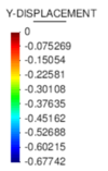
|
| (a) FEM code | (b) MPM code | |

|

| |
| (c) GMM-MLS code | (d) GMM-LME code | |
| Figure 4.2: Static cantilever. Displacement along y-direction | ||

|

|
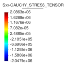
|
| (a) FEM code | (b) MPM code | |

|

| |
| (c) GMM-MLS code | (d) GMM-LME code | |
| Figure 4.3: Static cantilever. Cauchy stress along x-direction | ||
A convergence study is performed to analyse the accuracy of MPM and GMM in comparison with the UL-FEM. The error is evaluated as
|
|
(4.40) |
where is the numerical solution measure at point A (see Figure 4.1). Figure 4.4 depicts the error evolution in function of the inverse of the mesh size . It is demonstrated that all the methods have a quadratic rate of convergence. In particular, the UL-FEM, MPM and GMM-MLS error curves coincide. Regarding the error, evaluated with the GMM-LME algorithm, the quadratic rate is maintained, but the curve is shifted a bit upwards, which makes this technique less accurate than GMM-MLS in the benchmark case studied.
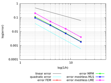
|
| Figure 4.4: Static cantilever. Convergence analysis |
4.5.2 Rolling of a rigid disk on an inclined plane
The second benchmark test is a rigid disk rolling without slipping on an inclined plane. The geometry of the problem is depicted in Figure 4.5. The disk is made of a hyperelastic material (presented in Section 3.1): the density is , the Young's modulus is and the Poisson's ratio is .
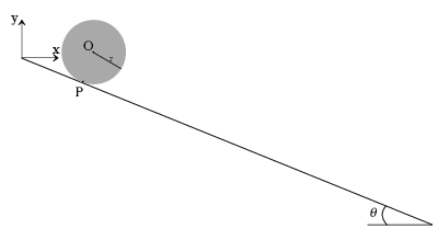
|
| Figure 4.5: Rolling disk. Geometry |
This test is chosen for an objective assessment of the robustness of the MPM and GMM algorithm. The rolling on the plane implies a contact between the nodes belonging to the inclined plane and the nodes belonging to the disk. In a UL-FEM code a contact algorithm would be necessary to set this boundary condition. On the contrary, by using either MPM or GMM, the contact is implicitly caught. The analytical acceleration () can be computed imposing the equilibrium of momentum at the contact point
|
|
(4.41) |
where is gravity and the angle of the inclined plane. Integrating over time the acceleration, velocity and displacement projected on the x-axis can be obtained as a function of time
|
|
(4.42) |
|
|
(4.43) |
For the study of this test case, the analytical solution of Equation 4.43 is used for the assessment of the absolute error obtained with MPM, GMM-MLS and GMM-LME, evaluated as
|
|
(4.44) |
where is the time where the numerical result is calculated. As a mesh-based and a meshless techniques are compared in a dynamic test, for a more objective comparison, the error is analysed along with the total computational time, needed to finalize the simulation.
A triangular mesh with mesh size is used for MPM and GMM simulations. In both techniques the same initial distribution of material points is used, which counts for three initial particles for cell. Regarding the GMM-MLS the approximants are constructed by adopting a search radius and a dilation parameter . In GMM-LME the basis functions are evaluated using a search radius and three values of dilation parameter . All the numerical tests are repeated for three different time steps with .
Table 4.1 shows the results of the analysis, in terms of errors and computational times, performed through MPM, GMM-MLS and GMM-LME.
| MPM | 2.34 | 232.72 | 1.27 | 472.92 | 0.91 | 894.91 |
| GMM-MLS | 0.84 | 264.78 | 0.26 | 517 | 0.20 | 981.82 |
| GMM-LME | 1.37 | 234.32 | 0.07 | 460.73 | 0.06 | 971.29 |
| GMM-LME | 0.9 | 237.22 | 0.23 | 460.50 | 0.07 | 1005.21 |
| GMM-LME | 0.52 | 232.42 | 0.07 | 466.63 | 0.06 | 1038.70 |
Regarding the absolute errors, it can be observed that, for a given computational cost, GMM is generally more accurate than MPM, because of the use of smooth basis functions which provide a better approximation of the unknown variables. In particular GMM-LME presents smaller errors in comparison to GMM-MLS. In all the three cases considered (with ) the errors converge to a unique value at the same computational time, while in the case of GMM-MLS, the advantage of using higher order elements is lost for the smallest delta time. Regarding MPM, it is established that to achieve the same order of accuracy of GMM a higher computational time must be expected, due to either a finer discretisation in space or in time. However, it is worth highlighting that GMM is much more time consuming than MPM, showing an increment of computational time of in the case of GMM-MLS and from up to in the case of GMM-LME.
In this example, some essential conclusions can be drawn. In Section 4.5.1 it was observed that in a static case the rate of convergence is the same for all the methods under analysis, but the accuracy of GMM-MLS and MPM is better than the GMM-LME. On the contrary, in a dynamic case with a contact problem, the result is overturned. In fact a better behaviour is noted if LME approximants are employed.
In Figures 4.6a, 4.6b and 4.6c the distribution of the module of velocity field within the disk is shown for the test case solved by means of the MPM, GMM-MLS and GMM-LME, respectively. As expected, the minimum velocity is localized in the region of the disk close to the contact point with the inclined plane; while maximum velocity is observed on the opposite part of the disk.
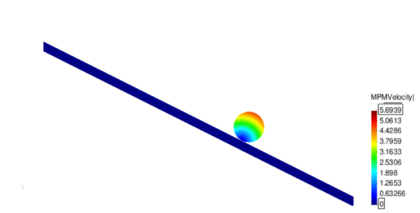
|
| (a) |
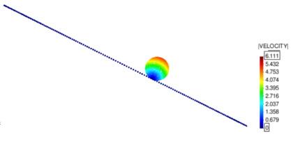
|
| (b) |
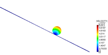
|
| (c) |
| Figure 4.6: Rolling disk. Absolute velocity field in test case solved with MPM (a), GMM-MLS (b) and GMM-LME with (c) |
4.5.3 Cohesive soil column collapse
The third example is the simulation of a soil column collapse. The column is modelled with a cohesive-frictional material, defined by a cohesion , a friction angle , an elastic bulk modulus and a density . In the current work the Mohr-Coulomb plastic law in finite strains with implicit integration scheme in principal stress space, presented in Section 3.3, is employed.
This test has been chosen for the assessment of the robustness of MPM and GMM when the body undergoes really large deformation. The results are compared with the work of [56], where a Smooth Particle Hydrodynamics method (SPH) is applied to geotechnical problems.
The initial geometry and the boundary conditions are described by Figure 4.7.

|
| Figure 4.7: Granular column collapse. Geometry |
Quadrilateral elements with an initial distribution of four material points per cell are used in the simulations. Two different mesh sizes are considered: (Mesh1) and (Mesh2). In GMM the basis functions are evaluated using an initial search radius , a dilation parameter and , in GMM-MLS and GMM-LME, respectively. In this particular case, the procedure for the evaluation of the basis functions in MLS and LME technique has been modified to avoid the creation of a non-convex hull of nodes which might lead to an incorrect set of approximants. This is required because the column is subjected to extremely large deformations. While in the previous examples a constant radius was used for the definition of the cloud of nodes surrounding a material point, in the current example a variable radius is adopted to guarantee a minimum number of nodes in each connectivity. In the case of LME, as a Newton iterative procedure is used for the evaluation of the shape functions, a measure of the goodness of the solution is represented by the condition number of the Hessian matrix , defined in [145]. If exceeds a user-defined tolerance, the LME algorithm is repeated considering the old connectivity plus an additional node, chosen as the next node closer to the material point. In the case of MLS, it has been sufficient to impose a minimum number of six nodes in each cloud of nodes. In Figure 4.8 a comparison of the column deformation at different representative time instants is shown. The SPH model taken from [56] predicts a higher final run-out of the column collapse, while the final configurations at time of MPM, GMM-LME and GMM-MLS are almost coincident using Mesh1 and Mesh2. It is worth highlighting that GMM-MLS and MPM results of Figure 4.8 are always in good agreement. However, this is not the case if the evolution of the equivalent plastic strains is observed (see Figures 4.9 and 4.10). In the case of GMM-LME, an improvement of the results is noted by using the finer mesh (Mesh2) in terms of displacements (Figure 4.8b) and equivalent plastic strains distribution (Figure 4.11b). Regarding MPM, it is proved that a good approximation can be obtained using both meshes.
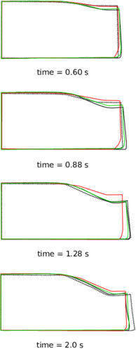
|
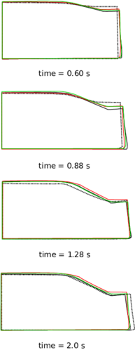
|
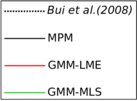
|
| (a) Mesh 1 | (b) Mesh 2 | |
| Figure 4.8: Soil column collapse. Configurations of the column at different representative time instants. | ||
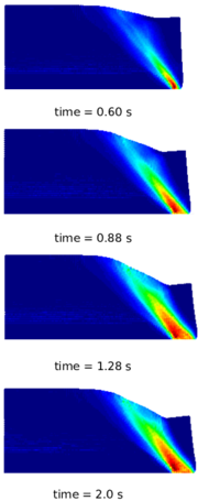
|
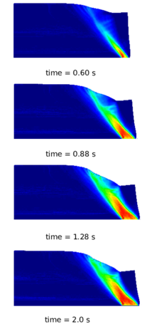
|
| (a) Mesh 1 | (b) Mesh 2 |
| Figure 4.9: Soil column collapse. Distribution of equivalent plastic strains for different representative time instants in MPM results. | |
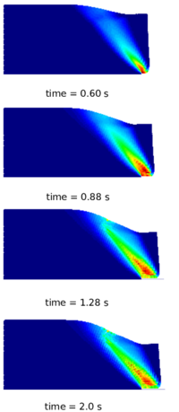
|
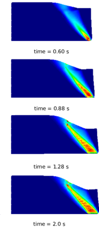
|
| (a) Mesh 1 | (b) Mesh 2 |
| Figure 4.10: Soil column collapse. Distribution of equivalent plastic strains for different representative time instants in GMM-MLS results. | |
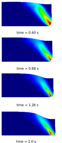
|
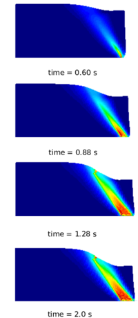
|
| (a) Mesh 1 | (b) Mesh 2 |
| Figure 4.11: Soil column collapse. Distribution of equivalent plastic strains for different representative time instants in GMM-LME results. | |
In this example, the capability of handling history-dependent materials, such as cohesive-frictional materials, is verified for both methods. It is noted that, in MPM large deformations can be naturally tracked without modifying the algorithm and accurate results are obtained also using the coarser mesh. In GMM, despite the remarkable features highlighted in the previous benchmark tests, when the continuum undergoes extremely large deformations, special care should be taken in the definition of the MLS and LME approximants. In this regard a lack of robustness of the GMM algorithm is observed due to the impossibility of guaranteeing a correct evaluation of the shape functions during the whole deformation process without an ad hoc modification of the procedure for the definition of the connectivity. Thus, for the solution of this example a correction of the algorithm has been performed and verified to work properly, albeit an increase in the computational time is registered. The establishment of a more general procedure is left for future work.
4.6 Discussion
In this Chapter, two particle methods: a Material Point Method and a Galerkin Meshless Method are tested and compared to assess their capabilities in solving large displacement and large deformation problems. A variational displacement-based formulation, based on an Updated Lagrangian description, is presented and its derivation is described in detail.
A comparison of MPM and GMM is performed through three benchmark tests and the methods are assessed in terms of accuracy, computational time and robustness. The first example is a static cantilever beam. A convergence analysis is performed and all the techniques have a quadratic convergence rate (compared to a FEM code). Secondly, the dynamic test of a rolling disk on an inclined plane is considered. The robustness of MPM and GMM in dealing with contact between two rigid bodies is tested and an analysis in terms of computational time and error is performed. It is found that GMM, in dynamic cases, has a higher accuracy than MPM, despite a higher computational cost. This is because in MPM linear basis functions are considered, while in GMM smooth basis functions are computed allowing to obtain a superior approximation of the unknown variables. As a last example, a cohesive soil column collapse is analysed. In this case, it is assessed the robustness of both methods when the continuum undergoes extremely large deformation. Firstly, it is demonstrated that MPM and GMM can be easily coupled with local plastic laws. Furthermore, it is noted that MPM leads to more accurate results and the algorithm does not need to be modified in a large deformation case. On the contrary, in GMM, a modification of the algorithm has to be considered to avoid the formation of non-convex hull of nodes when the connectivity is defined. Nonetheless, in spite of this modification, a discrepancy in the results is noted, by using either the MLS or the LME technique.
In conclusion, the standard version of MPM represents a good choice to handle problems involving history-dependent materials and large deformations. Regarding GMM, the accuracy of the solution strictly depends on the chosen basis functions. If large deformation of the continuum is not taken into account, this method could be preferred to MPM due to its remarkable feature in getting accurate results at a limited computational time. However, under finite strains regime, independently on the material to model, the construction of a connectivity in the meshless method becomes more complex and, at least to the authors’ knowledge, a general methodology is still missing to properly define a correct connectivity under any deformation condition. Thus, despite the promising features of this approach, an improvement in the robustness of the GMM algorithm is needed to obtain more accurate and reliable solutions in large deformation and failure problems, leaving the MPM, currently, the most suited numerical strategy for the analysis of granular flows.
5 Mixed formulation
In the field of granular flow modelling, there might be some cases where the granular matter undergoes undrained conditions. This corresponds to a situation where the bulk modulus K is much higher than the shear modulus G, and shearing deformations will be more important than dilation or compression in the overall response of the body. In this case, the behaviour of the body is usually approximated by assuming it to be incompressible. In the field of Finite Element Analysis (FEA) it is well established that results may suffer from volumetric locking issues, which can be detrimental for the solution itself when an irreducible formulation is employed. In this Chapter, the numerical strategy of a stabilized mixed formulation for the solution of non-linear solid mechanics problems in nearly-incompressible conditions is presented. The proposed mixed formulation, with displacement and pressure as primary variables, is implemented in the implicit MPM strategy, whose algorithm has been previously described in Chapter 2. The mixed formulation is tested through classical benchmarks in solid mechanics where a hypereleastic Neo-Hookean and a J2-plastic laws are employed. Further, the stabilized mixed formulation is compared with a displacement-based formulation, described in Chapter 4 to demonstrate how the proposed approach gets better results in terms of accuracy, not only when incompressible materials are simulated, but also in the case of compressible ones.
5.1 Introduction
The solution of solid mechanics problems in large displacement and large deformation regime, dealing with incompressible or nearly incompressible materials, is a topic of paramount importance in the computational mechanics community since many engineering problems present such conditions. It is well known that overly stiff numerical solutions appear when Poisson's ratio tends to 0.5 or when plastic flow is constrained by the volume conservation condition. In these cases, a standard Galerkin displacement-based formulation (u formulation) fails [159,146] due to the inability to evaluate the correct strain field. In the literature, many possible solutions can be found. For instance, Simo and Rifai introduced the Mixed Enhanced Element for small deformation problems [160]. This is a special three-field mixed finite element method in which the space of discrete strains is augmented with local functions. It is worth mentioning that also the class of B-bar methods [161] and the classical incompatible modes formulation [162] fall under this theory. For general purposes, some variants of this procedure are analysed in [163]. Alternative procedures suitable for geometrically non-linear regimes, are given by the F-BAR method [164], a technique based on the concept of multiplicative deviatoric/volumetric split in conjunction with the replacement of the compatible deformation gradient field, the non-linear B-bar method [165] and the family of enhanced elements [166], which represents an extension to the non-linear regime of the procedures exposed in [161] and [162], respectively. Though the good performance of all the aforementioned methods, none of such techniques is, however, suitable for application on simplicial meshes [167,146,168]. In this regards, among the successful strategies for the fulfilment of the incompressibility constraint, it is worth mentioning the group of the Mixed Variational Methods. Different researchers worked on mixed finite element formulations with displacement and mean stress as primary variables [169,170,171,172,173]; Cervera and coworkers, for instance, proposed a strain/displacement mixed formulation in the context of compressible and incompressible plasticity [174,175]; Simo et al. introduced a non linear version of a three-field Hu-Washizu Variational principle, where displacement, pressure and the Jacobian of the deformation gradient are independent field variables [176]. The use of Mixed Variational Methods and the difficulties encountered when applying them with different elements have been largely discussed in the 1970s. In [177,178,179,180] the need to satisfy the stability condition, the so-called inf-sup condition, is demonstrated and the instability and ineffectiveness of elements with equal-order interpolations for all the primary variables are proved. This has motivated the development of a series of stabilization techniques, which allow the employment of low order Galerkin finite elements in computational fluid dynamics and solid mechanics problems [181,182,183,184,185,186,187,188].
The treatment of the incompressibility constraint is relatively new in the context of the Material Point Method (MPM). Most MPM formulations deal with compressible materials, avoiding the issues arising from the imposition of the incompressibility constraint. However, some procedures for the treatment of locking issues can be found in the literature. For instance, in [189] an approach for the solution of kinematic (shearing and volumetric) locking is proposed. The authors identified the employment of linear shape functions in conjunction with a regular, rectangular grid, as cause of the locking. The mixed formulation, employed in such work, is derived from the definition of a three-field Hu-Washizu potential, with stress, strain and displacement considered as primary variables. In [190] the formulation presented makes use of the Chorin's projection [191], a popular fractional step formulation solved implicitly for fluid mechanics problems and in [192] a similar strategy, based on a splitting operator technique for solving the momentum equation, is proposed for the treatment of the incompressibility constraint.
In this Chapter, the computational strategy proposed in [139] for the solution of solid mechanics problems characterized by plastic incompressibility in large displacement and large deformation regime, is described in detail and applied to some representative test examples. A mixed u-p formulation, where the displacement and mean stress are considered as primary variables, is implemented within the framework of the implicit MPM strategy, developed in the Kratos Multiphysics open-source platform [29,30]. A monolithic solution strategy, which allows not to impose "spurious" pressure boundary conditions on the Neumann boundary, as done in [190,192], is used. In the current work, only simplicial elements are considered and a stabilization technique is adopted for the satisfaction of the inf-sup condition. The stabilization, based on the Polynomial Pressure Projection (PPP), presented in [193], is chosen for its ease of implementation and good performance demonstrated in previous works [194,195]. The proposed approach is validated through a series of benchmark examples, where an elastic Neo-Hookean and a J2 plastic material are employed. Further, for each test, the results obtained through a displacement-based (u) and the stabilized mixed (u-p) formulation are compared.
In what follows, the u-p formulation is derived in matrix form. Afterwards, the numerical examples are illustrated and the results are discussed.
5.2 The mixed formulation
In this section the mixed (u-p) formulation is briefly introduced and derived in matrix form.
5.2.1 Governing equations in strong form
Let us consider the body which occupies a region of the three-dimensional Euclidean space with a regular boundary in its reference configuration. A deformation of is defined by a one-to-one mapping
|
|
(5.1) |
that maps each point p of the body into a spatial point
|
|
(5.2) |
which represents the location of p in the deformed configuration of . The region of occupied by in its deformed configuration is denoted as .
The boundary value problem of finite elastostatics consists in finding a displacement field such that the equilibrium equations and the kinematic conditions are satisfied
|
|
(5.3) |
where is the Cauchy stress tensor, denotes the body forces and and the boundaries of , where both the normal tension () (being the outer normal) and the displacements () are prescribed.
As described in [159], the mixed formulation can be obtained expressing the system of Equations (5.3) in function of two primary variables: the displacement and the mean stress by splitting the stress tensor in its volumetric and deviatoric part . Thus, the system can be rewritten as
|
|
(5.4) |
being the second order identity tensor. We can observe that if is a solution of Equation (5.3), then , satisfying also , is a solution of Equation (5.4).
5.2.2 Weak form and linearisation of the weak form in spatial form
According to the standard FEM procedure, the weak form of Equation (5.4) is obtained by employing the Galerkin method and is written in spatial configuration, adopting an Updated Lagrangian framework.
For sake of clarity the weak form Equation 5.3, previously derived in Chapter 4, is provided below.
|
|
(5.5) |
using the notation .
With regard to the mixed formulation, linear interpolation finite elements both for displacement and pressure (u-p) are considered. The weak form of the balance of the linear momentum (Equation (5.5)) can be rewritten as
|
|
(5.6) |
where the Cauchy stress tensor is decomposed in its deviatoric and volumetric component, denoted as and , respectively. The weak form of the pressure continuity equation is obtained by performing a inner product of the second equation of (5.4) with an arbitrary test function , where is the space of virtual pressure. Finally the weak form of the pressure continuity equation is expressed as
|
|
(5.7) |
In this work a Newton-Raphson's iterative procedure is employed for the solution of problems characterized by material and geometrical non-linearities. The non-linear weak forms of Equations (5.6) and (5.7) have to be linearised through an expansion in Taylor's series, evaluated at the last known equilibrium configuration and .
In this way the solution system of linearised equations can be derived and expressed in matrix form as
|
|
(5.8) |
where and are the components of the residual vector, and are the vector of unknown displacements and unknown mean stresses, respectively. The components of the matrix on the left hand side (lhs) of Equation (5.8) are given by the tangent stiffness matrix , which can be seen as the sum of the material stiffness matrix
|
|
(5.9) |
being the fourth order identity tensor, and the geometric stiffness matrix
|
|
(5.10) |
Furthermore, is
|
|
(5.11) |
and the mixed terms and , are defined, respectively, as
|
|
(5.12) |
|
|
(5.13) |
where can be derived once determined the volumetric stress as function of the strain field.
One can observe that and are distinguished from and , defined for the irreducible formulation (Equations (4.34) and (4.33)). In the mixed case, the deviatoric part of and is separated by the volumetric one and an evaluation of the latter is done, not using the material response of the constitutive law, but the interpolation of the nodal pressure field on the material points, i.e., the integration points.
5.2.3 The stabilized mixed formulation
For the treatment of the incompressibility constraint, the Polynomial Pressure Projection (PPP), introduced by Dohrmann and Bochev [193], is used. This stabilization procedure is obtained by modifying the mixed variational equation by using a polynomial pressure projection. If is the order of the continuous polynomial shape functions used to approximate , the pressure projection is performed into a polynomial space with order of . As in the current work linear shape functions are used for the pressure, the polynomial pressure projection is made in a discontinuous space and, consequently, it can be performed at the element level as
|
|
(5.14) |
being the best approximation of in and an arbitrary test function, where is the space of polynomial functions with zero degree in each coordinate direction. Unlike other stabilization techniques, the pressure stabilization is accomplished without the use of the residual of the momentum equation; thus, the calculation of higher-order derivatives and the specification of a mesh-dependent stabilization parameter are avoided. Moreover, it is demonstrated that symmetry of the mixed formulation is retained.
In the case of simplicial elements, as in the current work, the stabilization of the unstable mixed formulation requires only the addition of the bilinear form
|
|
(5.15) |
to Equation (5.7), where is a parameter to be selected for stability and the shear modulus. The weak form of the pressure continuity equation (Equation (5.7)) can be rewritten as
|
|
(5.16) |
and the matrix system (Equation (5.8)) becomes
|
|
(5.17) |
where
|
|
(5.18) |
and
|
|
(5.19) |
5.3 The MPM algorithm in the framework of a mixed formulation
If a mixed (u-p) formulation is used in the framework of the MPM, it is important to highlight that some changes have to be considered in the initialization and convective phase of standard algorithm, described in Section 2.4.1. In the initialization phase, initial nodal pressure values , related to the previous time , have to be evaluated, in addition to the mass, velocity and acceleration ones, using the following expression:
|
|
(5.20) |
where is the shape function of node evaluated at the position of the material point, and and are the mass and the pressure of the material point, respectively. The nodal pressure evaluated in Equation (5.20) is used in the predictor step of the Newmark scheme. Once the solution is iteratively computed using the linearised system of Equations (5.17), the convective phase is performed, as explained in detail in Section 2.4.1. The pressure on the material points is updated in addition to the material point displacement, velocity and acceleration, through an interpolation of the converged nodal pressure values on the material point position
|
|
(5.21) |
The Algorithm 2.1, previously provided in Section 2.4.1, is below presented for a static case, together with the modifications aforementioned.
|
(we will use ), Material DATA: E, , |
| Initial data on material points: , , , and |
| Initial data on nodes: NONE - everything is discarded in the initialization phase |
| OUTPUT of calculations: |
|
|
Algorithm. 5.1 MPM algorithm in the framework of a mixed formulation. |
5.4 Numerical Examples
In this section, two numerical examples are presented for the validation of the mixed formulation. Firstly, the well-known benchmark test of a Cook's elastic membrane is considered and a mesh convergence study is performed. The stability of the mixed formulation is assessed in a quasi-incompressible elastic case. Secondly, a plane strain tension test of a J2-plastic plate in compressible and incompressible state is analysed. In this example, the performance of the irreducible u and the mixed u-p formulations are compared in the case of incompressible plastic flow. The results obtained with the u and u-p formulations are compared and used to demonstrate that a mixed MPM formulation can provide more accurate and reliable results, not only under the assumption of elastic and plastic incompressibility, but even in compressible situations.
In this work, a stabilization parameter () with value of 1 has been used. The direct solver SuperLU is employed for the solution of the system of linearised equations, both in the case of u and u-p formulations.
5.4.1 Cook's membrane problem
As a first numerical example, we consider the well known Cook's membrane test, proposed for the first time by Cook [196]. This test is often used as a benchmark to check the element formulation under compressible and incompressible conditions. In the literature, the Cook's membrane is commonly tested in infinitesimal deformation assumption and material linearity [171], geometric non-linearity and material linearity [197] and, finally, in geometric and material non-linearities [155,164,170,194]. The geometry and material properties of the problem are shown in Figure 5.1. A clamped trapezoidal plate, subjected to a distributed shear load, whose resultant force is , applied along the right side, is analysed. The static case is solved studying the response of a compressible and a quasi-incompressible Neo-Hookean material, whose formulation is presented in Section 3.1. The convergence study is performed using six structured triangular meshes each of which uses an initial value of one material point per element.

|
| Figure 5.1: Cook's membrane. Geometry, material properties and boundary conditions |
Since the formulations under study are based on the assumption of finite deformation and material non-linearity, the results relative to a very fine mesh (256 elements per side) of a FEM analsys is considered as reference solution in the compressible case, while the result of [194] is the benchmark solution for the quasi-incompressible case. The reference solution of vertical displacement at point A (Figure 5.1) is found to be 0.323m, in the compressible case, and 0.275m in the quasi-incompressible cases, respectively. The results of u and u-p formulations, with and without stabilization term (UP No Stab and UP Stab) are summarized in Table (5.1) for both the compressible and nearly incompressible cases. The same results can be observed graphically in Figures 5.2 and 5.3.
| Elements per side | Compressible case | Quasi-incompressible case | ||||
| U | UP No Stab | UP Stab | U | UP No Stab | UP Stab | |
| 2 | 0.089 | 0.1013 | 0.1172 | 0.0723 | 0.0788 | 0.1277 |
| 4 | 0.1415 | 0.1718 | 0.1953 | 0.0736 | 0.1157 | 0.1932 |
| 8 | 0.2183 | 0.2511 | 0.2669 | 0.0742 | 0.1821 | 0.2424 |
| 16 | 0.2771 | 0.2952 | 0.3025 | 0.075 | 0.2356 | 0.2648 |
| 32 | 0.30386 | 0.3119 | 0.315 | 0.0775 | 0.2606 | 0.2725 |
| 64 | 0.3133 | 0.3176 | 0.319 | 0.0862 | 0.2702 | 0.275 |
The u formulation is less accurate than the u-p formulation both for the UP No Stab and UP Stab cases, not only for the nearly incompressible condition, as expected, but also for the compressible one. However, the discrepancy is clearly visible in the quasi-incompressible problem (Figure 5.3), where the capability of the u formulation to predict the displacement field is compromised due to volumetric locking.
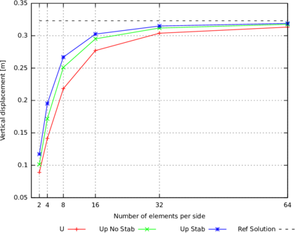
|
| Figure 5.2: Cook's membrane. Compressible case: vertical displacement at point A |
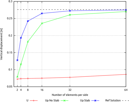
|
| Figure 5.3: Cook's membrane. Quasi-incompressible case: vertical displacement at point A |
Regarding the mixed approaches, from Figure 5.3 it is possible to infer that even not using a stabilization term the solution is not affected by volumetric locking. However, through the stabilized u-p formulation it is also possible to prevent pressure oscillation issues in the mean stress field, as can be observed in Figure 5.4, where the pressure values of Figure 5.4a are all out of the threshold defined by the solution of Figure 5.4b.
5.4.2 2D tension test
As second numerical example, a plane strain tension problem is considered to test the mixed formulation in an elasto-plastic regime. A 2D plate, clamped at the bottom of the specimen, is subjected to a prescribed vertical displacement on the upper side. Both geometry and material properties are taken from [173] and are depicted in Figure 5.5. The plate is made by a hyperelastic perfectly-plastic material which is simulated using a J2 plastic law, whose formulation is presented in Section 3.2. An unstructured triangular background mesh with a mesh size of 0.001m and an initial distribution of 12 material points per cell, which is found to give the optimal trade-off between accuracy of the results and computational cost in both the compressible and incompressible cases, are adopted.
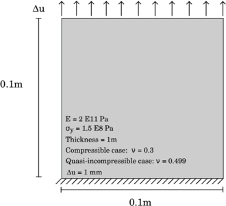
|
| Figure 5.5: Tension test. Geometry, material properties and boundary conditions |
The results of the compressible case are shown in Figures 5.6, 5.7, 5.8 and 5.9, where the displacement along x and y-direction, the equivalent plastic strains and the vertical Cauchy stresses are shown. Volumetric locking is not affecting the numerical results, as the plate is working under compressible conditions. However, the u-p formulation is more accurate than the u one, not only in the evaluation of the stress field, but also of the displacement field. Moreover, the goodness of the solution can be appreciated looking at Figure 5.8b: the equivalent plastic strains are distinctly distributed along a cross shape, while the result of Figure 5.8a revokes the same shape, but without the same order of precision. In conclusion, even if a compressible material is simulated, the results obtained with the u-p formulation present a higher order of accuracy, by using the same mesh size and the same number of material points per element.
The results of the incompressible case are shown in Figures 5.10, 5.11, 5.12 and 5.13. In this case, the u formulation fails in the simulation of the tension test. As expected, the displacement and stress fields are affected by volumetric locking and the plastic deformations are incorrectly localized. On the other hand, Figures 5.10b, 5.11b, 5.12b and 5.13b show that the u-p formulation is able to evaluate correctly the displacement and stress field under incompressible conditions. The results are similar to those depicted in Figures 5.6b, 5.7b, 5.8b and 5.9b: the cross-shape distribution of the equivalent plastic strains and stresses are recovered. Furthermore, Figures 5.14a, 5.14b, 5.14c and 5.14d show a comparison in the nearly-incompressible case between the reference solution obtained with the formulation proposed in [173] and the results obtained with the MPM u-p formulation presented in the current work. We can observe that there is a good agreement both in the distribution of equivalent plastic strains and pressure fields and in their values range. Finally, the stress - displacement curve, evaluated with the mixed formulation, is shown in Figure 5.15. The results for the compressible and incompressible cases are in good agreement. Both correctly predict the elastic regime and the inception of the plastic flow when the yield stress is reached.
Since a mixed formulation with displacement and pressure as primary variables is adopted, strains are not linearly distributed within the element, but these coincide with a constant function. It is worth highlighting that through this numerical procedure while it is possible to avoid the volumetric locking, the problems related with strain localization are still present. This means that the width of the shear bands still depends on the size of the elements. This problem can be solved by regularization of the element size as proposed, e.g. in [198,174,175] or [156], where the formulations consider the strain field as primary variable and, therefore, its linear distribution can be evaluated, which allows to accurately predict strain localization with mesh independence.
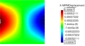
|
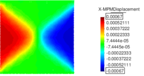
|
| (a) u formulation | (b) u-p formulation |
| Figure 5.6: Tension test. Compressible case: horizontal displacement | |
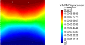
|
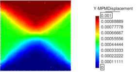
|
| (a) u formulation | (b) u-p formulation |
| Figure 5.7: Tension test. Compressible case: vertical displacement | |
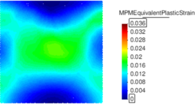
|
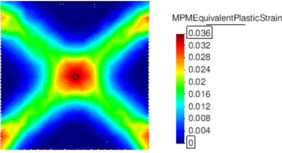
|
| (a) u formulation | (b) u-p formulation |
| Figure 5.8: Tension test. Compressible case: equivalent plastic strain | |
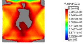
|
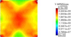
|
| (a) u formulation | (b) u-p formulation |
| Figure 5.9: Tension test. Compressible case: Cauchy stress along loading axis. Black contour colour should be intended as out of range. | |
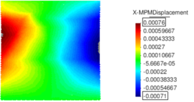
|
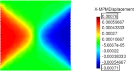
|
| (a) u formulation | (b) u-p formulation |
| Figure 5.10: Tension test. Incompressible case: horizontal displacement | |

|

|
| (a) u formulation | (b) u-p formulation |
| Figure 5.11: Tension test. Incompressible case: vertical displacement | |

|

|
| (a) u formulation | (b) u-p formulation |
| Figure 5.12: Tension test. Incompressible case: equivalent plastic strain | |
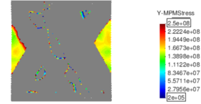
|
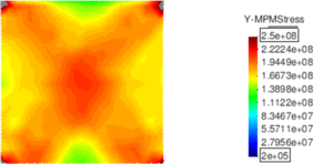
|
| (a) u formulation | (b) u-p formulation |
| Figure 5.13: Tension test. Incompressible case: Cauchy stress along loading axis. Black contour colour should be intended as out of range. | |
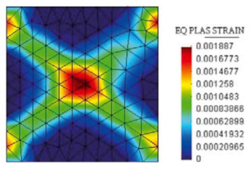
|
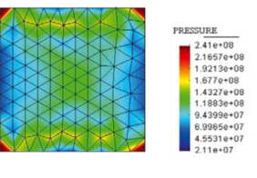
|
| (a) Equivalent plastic strain | (b) Pressure |
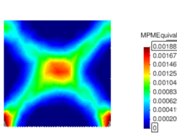
|
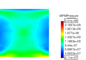
|
| (c) Equivalent plastic strain | (d) Pressure |
| Figure 5.14: Tension test. Incompressible case: results evaluated at a total imposed vertical displacement of 0.0001m. a) and b) Results in terms of equivalent plastic strain and pressure using a T1/P1 u-p formulation, taken from [173]. c) and d) Results in terms of equivalent plastic strain and pressure evaluated with the MPM u-p formulation presented in the current study. | |
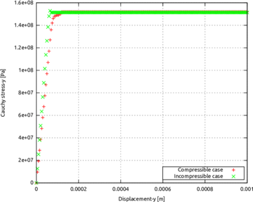
|
| Figure 5.15: Tension test. Stress-Displacement curve. Comparison between the compressible case (red curve) and the incompressible curve (green curve). |
5.5 Discussion
In this Chapter, a stabilized mixed u-p formulation is presented in its strong and weak forms. The formulation is implemented within the framework of the implicit MPM strategy, able to solve problems which involve large displacements and large deformations. The irreducible u and mixed u-p formulations are tested and compared through a series of benchmark examples. Firstly, the Cook's membrane problem, a bending dominated test, is investigated. Two cases, a compressible and a nearly-incompressible one, are solved through the u and u-p formulations. From the results, it is demonstrated that the u-p formulation always gives the best performance in term of convergence. In the quasi-incompressible case, the volumetric locking issue is overcome and pressure oscillations are avoided if a stabilization term is added to the mixed finite element formulation. In the second example, a J2 plastic plate, subjected to uniform tension on one side and fixed to the other side, is under study and both formulations are tested under an isochoric plastic flow condition. By comparing the displacement-based and mixed formulation it is shown that, even in this case, better results are obtained through the u-p procedure. Indeed, a higher definition of displacement, equivalent plastic strains and vertical Cauchy stress fields is observed. Despite volumetric locking issue is fixed in the case of the u-p formulation, further problems, such as, mesh independence and strain localization, are not addressed in the current work and they would represent interesting topics for a future research.
In conclusion, it is demonstrated that the u-p formulation can evaluate more accurate results in terms of displacement and stress fields, not only under near-incompressible state, avoiding the typical drawback of volumetric locking, but even under compressible conditions.
6 Validation
In Chapter 2 the Material Point Method and its algorithm have been presented. Under the assumption of finite strains an irreducible (see Chapter 4) and a mixed formulation (see Chapter 5) are described and verified by using the constitutive laws, whose algorithms are shown in detail in Chapter 3. In the current Chapter, the MPM numerical strategy, implemented within the Kratos Multiphysics framework, is employed for the solution of typical problems concerning granular flows, involving large displacement and large deformation of the continuum under study.
Firstly, the typical granular column collapse is considered. For the validation of such a case, the comprehensive experimental work of Lube and co-workers [199] is used as a reference. In the second part of the current Chapter, a second example is taken into account: the rigid strip footing test, a typical test in geomechanics for the assessment of the bearing capacity of a soil to an imposed displacement or force. In the examples considered, experimental results will be used for validation, otherwise, solutions of other studies, available in the literature, will be used as a reference.
In this section, the granular collapse on a horizontal plane is considered as a test case for validation. This test has been chosen because, despite the apparent simplicity of the experiment, the description and prediction of the collapse is still a challenge from an experimental, numerical and theoretical point of view [200]. It is a perfect example to test the numerical technique in case of large displacement and large strain. Indeed, inertial granular flows are characterized by unsteady motion, a large variation of the free surface with time and propagation toward the free surface of internal interface separating the static and flowing regions. During the last decades, this test has been object of numerical study of many research groups by using techniques based either on discrete or continuum mechanics. Regarding the use of DEM, Staron and Hinch [201] showed that their results have good agreement with the experimental results in terms of run-out distance, but they did not provide a physical argument able to explain the relation between the initial aspect ratio and the final run-out. Moreover, they focused on the final deposition profiles without paying attention to the influence of material properties and the collapse mechanism. In Lacaze et al. [202], DEM simulations are performed providing good results; they focused on both flow behaviour and final deposition of the collapse. In Kumar [203] DEM simulations are carried out with an analysis on the initial grain properties, which is demonstrated that can influence the structure of internal flow and the kinematic of failure mechanism. The use of DEM, in the context of micro-mechanical analysis, is really helpful in providing some insights. However, when extending to upper scales, the method suffers from extremely demanding computational cost, which is detrimental for its usage to practical application in the engineering and industrial framework. Due to this aspect, a high interest of the computational community is sparked in solving granular flow problems with techniques based on continuum mechanics, which have the advantage to reduce tremendously the computational cost. Some attempts have been carried out by using an ALE FEM [204] or SPH [205,206]. However, as pointed out in Chapter 2, these methods suffer from some issues which do not make them particularly suitable for the modelling of granular flows. The granular column collapse has been also modelled with the MPM [118,207]. In [118] a validation is performed by employing a Mohr-Coulomb plastic law, while in [207] an analysis of different constitutive laws implemented in a MPM code is carried out and interesting insights are provided on the choice of a suitable constitutive model regarding the modelling of granular material flows.
In this section, the results of the comprehensive experimental work of Lube and co-worker [199] are used as a reference for the validation of the MPM code implemented in the Kratos Multiphysics framework. In their works, the authors observed that the final run-out, the final maximum height and the corresponding time, indicated with , and , respectively, to be consistent with the reference works, are found to be independent on the different grains and roughness of the lower boundary and only the initial geometry, the initial aspect ratio, could affect those results. The experimental test consists in a granular column inside a channel, wide enough in order to avoid the wall influence, at one side sustained by a fixed wall and on the other side by a moving wall. At the beginning, the column is at rest and the experiment starts when the moving wall is removed and the granular material is free to collapse.
In this validation work, granular columns of different aspect ratios, , are considered. It is well known that the first failure surface, which generates after the opening of the moving wall, is very similar in all the sample independently of the initial geometry [199,207]. Hence, the amount of mass which starts moving from the static zone increases with the initial aspect ratios and, consequently, different flow regimes might take place depending on the initial geometry of the column. For taller aspect ratios (), the flow regime is mainly dominated by the inertia (Regime I); in the case of low aspect ratios, the flow behaviour is more dominated by the friction and energy dissipation (Regime II) which takes place at the bottom layer, at the interface between static and dynamic zone and in the moving mass, as well. With regards to the kinematic of the granular column collapse, it has been experimentally observed that in Regime I three transient stages can be distinguished: a constant acceleration phase at , a constant velocity and a final deceleration stage. The duration of the second stage decreases with and for aspect ratios lower than 1.5 does not appear. Thus, in Regime II only two stages of initial acceleration and final deceleration take place.
In this test case, the Mohr-Coulomb plastic law, presented in Section 3.3, is employed. It is well known that one of the limitations of this constitutive model lies on the inability to express the dissipation due to friction between grains during the transition from static to flowing regime and vice-versa. As done in [118], also in this work of validation a numerical dissipation is added to the matricial formulation to be solved, presented in Chapter 4. It is found that the Rayleigh damping alpha coefficient with a value of 1.5 can replicate with good accuracy the reference solution, as shown in the following paragraphs.
The power-laws deduced in the experimental study [199] are used for the prediction of , and as
|
|
(6.1) |
|
|
(6.2) |
|
|
(6.3) |
In this validation study three different mesh discretisations are employed with a cell size of and , defined as Mesh 1, Mesh 2, Mesh 3, respectively, and in what follows, the effect of mesh refinement on the kinematic of granular column collapse is analysed. A number of initial material points per element is set to 9 in all the analyses and the material properties are listed in Table table: granular column material properties.
| Young Modulus | Poisson ratio | Density | Internal friction angle | Dilatancy angle | Cohesion |
| 0.84e6 Pa | 0.3 | 2600 kg/mc | 31 deg | 1 deg | 0 Pa |
The numerical results are summarized in Tables 6.2, 6.1 and 6.1, and the results, evaluated according to the power laws of Equations 6.1, 6.2 and 6.3, in Table 6.1. It is found that, in general, by using more fine mesh the values of , and approach the empirical values of Table 6.1.
|
| ||||||||||||||||||||||||||||||||||||||||||||||||
|
| ||||||||||||||||||||||||||||||||||||||||||||
In order to carry out a comparison between the experimental and numerical results with regards to the kinematic of the failure mechanism, in Figures 6.1 and 6.2 experimental and numerical normalized distance-time data of the flow front for the test with aspect ratios 3, 5 and 7 are depicted. The normalize distance is evaluate as , while the normalized time has the following expression
|
|
(6.4) |
where it is used the empirical law for high aspect ratios, obtained in [199], which states that the time for the column to spread depends only on the initial height .
In Figure 6.1 the results obtained with the finer mesh (Mesh 3) are depicted. It is found that the sample with the aspect ratio of 3 is the numerical test which fully matches the yellow region, within which all the experimental normalized distance-time data collapse. The higher the aspect ratio, the higher the mismatch between numerical and experimental results. By observing Figures 6.2a, 6.2b and 6.2c, it is found that the numerical results in terms of kinematic of the moving front do not show a sensitivity to the different spatial discretisations. Moreover, the typical three stages of the failure mechanism: the initial constant acceleration, the constant velocity and the final deceleration step, are recognized for all aspect ratios. If in Figure 6.2a it is shown that the numerical results fall in the yellow zone, for higher values of aspect ratio (see Figures 6.2b and 6.2c), the curves slightly deviate from the yellow zone. It is deduced that the velocity, in the second stage, is higher than what experimentally observed. This implies that in the numerical simulations the amount of energy dissipated is underestimated, even if a damping term is added to the matricial system to solve.
![Granular column collapse: comparison between normalized distance-time data for different aspect ratios with Mesh 3 and experimental results [199].](/wd/images/thumb/4/43/Draft_Samper_987121664-monograph-normalized_dist_time_mesh3_text-0_4cm-0_6cm-0_7cm-1_8cm.png/500px-Draft_Samper_987121664-monograph-normalized_dist_time_mesh3_text-0_4cm-0_6cm-0_7cm-1_8cm.png)
|
| Figure 6.1: Granular column collapse: comparison between normalized distance-time data for different aspect ratios with Mesh 3 and experimental results [199]. |
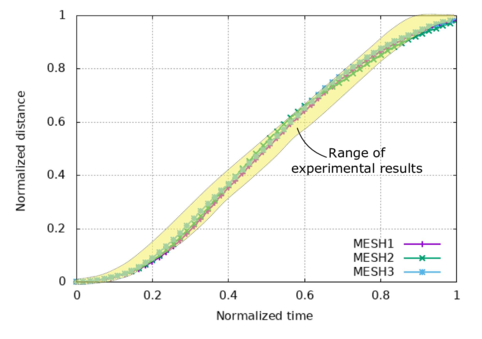
|
| (a) Case a = 3 |
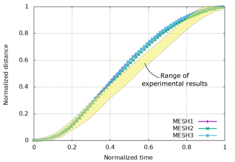
|
| (b) Case a = 5 |
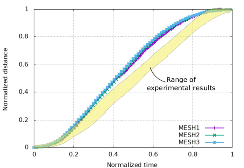
|
| (c) Case a = 7 |
| Figure 6.2: Granular column collapse: comparison between normalized distance-time data of the flow front for different aspect ratios a. |
In addition, for the test case with the configurations of the granular column at different times of the analysis are compared with the experimental ones in Figure 6.4. From the comparison it is found that the numerical results have a good match with the experimental one, except for the maximum height of the column at the position in all the time instants considered, most probably due to the adoption of a constitutive law unable to predict the initial failure surface and, thus, the correct flowing behaviour.
The results of Figure 6.4, to some extent, can be considered accurate, providing a good description not only of the final configuration, but also of the dynamic flowing behaviour at different times. Nevertheless, as pointed out in Fern [207], numerical damping aims to mitigate numerical oscillations by reducing the out-of-balance force and is, hence, reducing the dynamic effects. The use of numerical damping to reduce the run-out distance is rather a modification of the dynamic problem than a proper energy dissipating mechanism. In [207] it is confirmed that the initial geometry of the column plays an important role in the dynamics of the failure mechanism, since it establishes the initial potential energy available in the system. From the modelling point of view of such test case an accurate representation of the real triggering mechanism and the flow behaviour it is on the constitutive law which it is found to have two main roles. It defines the first failure surface, thus, the amount of potential energy to be transformed in kinetic energy and to be dissipated, and the way energy is dissipated in the system of the moving mass. As a last observation, in [207] they recognized the initial density as important variable to be considered in the model, able to influence the constitutive model enhancing the mechanical response. It influences the dilatancy characteristics and consequently the failure angle. The enhancement of the angle of failure by density influences, in turn, the volume of the mobilised mass, its potential energy and, in some cases, the dissipation of that energy. They noticed that the initial density affects more the results in low aspect ratios column and this could explain the difference between Regime I and Regime II from a physical point of view. The observations made in the work of Fern and Soga give a critical view of some constitutive models, for instance, the Mohr-Coulomb plastic law adopted in the current work, which are not able to predict the real energy dissipation that should have taken place during the failure mechanism (observed in the current work mainly for higher aspect ratios) and the evolution of density before reaching the critical state.

|

|
| (a) t1 | (b) t2 |

|

|
| (c) t3 | (d) t4 |
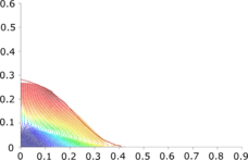
|

|
| (e) t5 | (f) t6 |

|
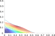
|
| (g) t7 | (h) t8 |
| Figure 6.3: Granular column collapse: Contour fill of the numerical results and the experimental shape of the column collapse [199] in different time instants. | |
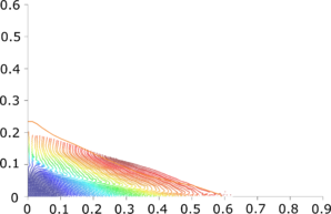
|
| (i) t9 |
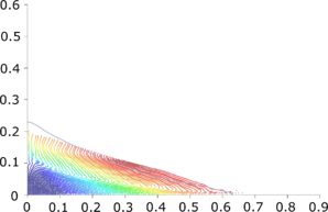
|
| (j) t10 |
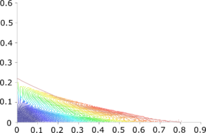
|
| (k) t11 |
| Figure 6.4: Granular column collapse: Contour fill of the numerical results and the experimental shape of the column collapse [199] in different time instants. |
6.2 Plain strain rigid footing on undrained soil
The second test of validation is a plain strain rigid strip footing for the evaluation of the bearing capacity of the soil in undrained conditions, underneath the foundation. The soil is modelled as a purely cohesive weightless elastic-perfectly plastic Mohr-Coulomb material with associative flow rule, which is presented in Section 3.3. The geometry, the boundary conditions and material properties are represented in Figure 6.5, where for symmetry only half of the domain is considered.
In the geomechanics community this is a classical benchmark for the validation of the constitutive law and of the numerical method adopted for its simulation. In the literature, the rigid strip footing has been studied by many authors. In [208] Nazem and coworkers solved this example in three different kinematics frameworks: a Total Lagrangian (TL), an Updated Lagrangian (UL) and an Arbitrary Lagrangian Eulerian (ALE) Finite Element Methods. They show that for large deformations an ALE method is more suitable than UL and TL strategies, avoiding mesh distortion with a remeshing technique. Even if the remeshing could smear a stress concentration and compromise the strain localization, they found that the load-displacement curve is comparable with the numerical solutions available in the literature. In [209] the technique of [208] is generalized to the case of higher order elements. The same test example has been also used to prove that the MPM represents an ideal numerical approach since it naturally tracks large deformations without the need of remeshing procedures. For instance, in [118] this example is successfully solved exploiting the capability of MPM to track large deformation and large displacement of the solid. However, the work of [118] is limited to the infinitesimal strain assumption.
For the validation of this test case, the stabilized mixed formulation, valid under geometric and material non-linearities, presented in Chapter 5, is employed, generalizing the approach used in [118]. The simulation is performed using displacement control with steps of incremental vertical displacement . The total displacement has been imposed in 2000 time steps which corresponds to twice the foundation width . The discretisation of the computational domain is performed through a unstructured triangular background mesh with a mesh size of 0.05m. At the interface between the foundation and the soil, where the largest deformations take place, a higher initial number of material points per element is used for a better resolution of the results (Figure 6.5).
In Figures 6.6, 6.7 and 6.8 the displacement and stress fields obtained with the u and u-p formulations are compared. As expected, the latter shows to be more reliable and accurate than the first one. It can be noted that the final deformation is accurately described and an improvement is registered if the final deformation is compared with the numerical results of [208] and [209] which are more similar to the final configuration obtained through the displacement-based formulation. The need for a mixed formulation is evident when evaluating the vertical stress field. In Figure 6.8a the displacement-based formulation fails to evaluate a reliable stress response, as the magnitude of the vertical Cauchy stress is out of the expected range in the area where the foundation buries itself. On the other hand, the mixed formulation is able to evaluate a continuous stress field and using such result it is possible to evaluate the normalised load-displacement response of the foundation, which is used for the validation of the current example.
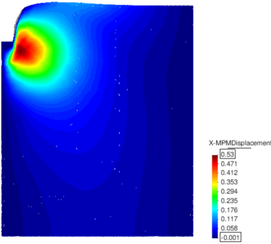
|
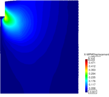
|
| (a) u formulation | (b) u-p formulation |
| Figure 6.6: Rigid strip footing. Horizontal displacement | |
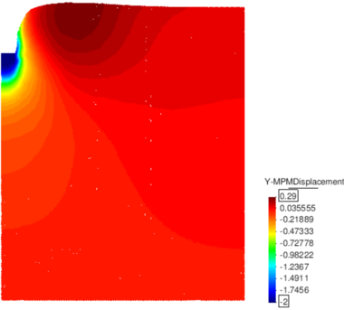
|
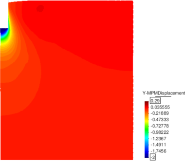
|
| (a) u formulation | (b) u-p formulation |
| Figure 6.7: Rigid strip footing. Vertical displacement | |
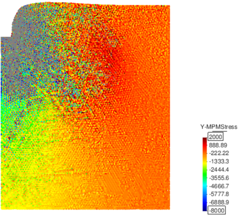
|
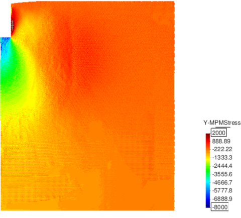
|
| (a) u formulation | (b) u-p formulation |
| Figure 6.8: Rigid strip footing. Vertical Cauchy stress | |
Since the problem has no analytical solution, the numerical result of [210], obtained through a sequential limit analysis formulation, is taken as reference solution. The problem is solved under the assumption of large deformations, hence, the bearing capacity of the soil is expected to be higher than the value of which corresponds to the small deformation case, for a given footing displacement. Under this hypothesis, the mobilized soil resistance does not reach an asymptotic value, but gradually increases, as explained in [210]. In Figure 6.9, the result obtained through the u-p formulation in terms of normalized bearing capacity of the soil, as a function of the normalized settlement, is depicted and compared with the benchmark solution. It can be observed that, the obtained curve is in good agreement with the reference solution [210]. The discrepancy that is observed for the initial values of the settlement is the consequence of the chosen material elastic properties. The Young Modulus and the Poisson's ratio have values which correspond to an undrained bulk modulus of , which gives a ratio . In [118], the influence of this ratio on the normalised load-displacement curve is studied: the elastic response of the soil becomes less or more important and the bearing capacity of the soil can increase or decrease, for higher or lower values of this ratio, respectively. For this reason the numerical results plotted in Figure 6.9 have an important elastic response and are deviating during the initial phase of the simulation from the perfectly rigid behaviour of the benchmark solution.
![Rigid strip footing. Normalised load-displacement curve: comparison between reference solution taken from [210] and the u-p formulation solution presented in this work.](/wd/images/thumb/b/b0/Draft_Samper_987121664-monograph-load_disp_finer.png/360px-Draft_Samper_987121664-monograph-load_disp_finer.png)
|
| Figure 6.9: Rigid strip footing. Normalised load-displacement curve: comparison between reference solution taken from [210] and the u-p formulation solution presented in this work. |
The example of the rigid footing on undrained soil has been validated using a stabilized mixed MPM formulation. The soil bearing capacity is well predicted and comparable with accurate numerical results from the literature. Moreover, a good description of the final deformation of the soil is achieved by using the MPM and its capability of solving large displacement and large deformation problems is equivalent, if not superior, to other techniques proposed in the literature [208,209].
6.3 Discussion
In this Chapter, two test cases are proposed for the validation of the MPM strategy, by using an irreducible and a mixed formulation. The first test is represented by the granular column collapse, a classical example which is quite often considered for the validation of both the constitutive laws and the numerical techniques. Despite its simplicity, with this test it is possible to make an assessment of the robustness of the numerical model and understand to what extent the constitutive law can provide reliable results. It has been shown that the MPM code, object of study, is able to track with accuracy the configuration of the collapse at different time frames and the constitutive law, employed in this study, can provide good enough results, even if neither softening and density variable are considered as additional terms in the dissipation plastic process. In this regard, as future work, further constitutive models should be taken into account, in order to improve the prediction capability of this numerical strategy. As a second example for validation, the rigid footing on undrained soil is considered. In this case, the good performance of the u-p formulation are tested also under the finite deformation regime: a higher accuracy of the displacement and stress fields are confirmed. Moreover, evaluating the bearing capacity as a function of the footing displacement, the load-displacement curve is obtained and used as a validation tool to be compared with a reference solution.
7 Application to an industrial case
In this Chapter, our Material Point Method formulation is applied in an industrial framework. Several laboratory tests, carried out at the Nestlé Laboratories aiming at the characterization of flowability of different sugar powders, are reproduced numerically. The practical objective of this work lies on the assessment of flow performance of sugar powders, which can play an important role in product development. In case ingredient properties are not optimized a significant variability can be observed during the operation of filling of jars or sachets, which may be detrimental for the production line. In this study, we propose to discuss the performance of crystalline sugar. If the experimental investigation of food materials process is essential in this context, the capability of numerically modelling particulate processes might represent a complementary tool for a better and a more realistic understanding of the process at a pilot or industrial scale. It is experimentally found that the flow quality is strongly deteriorated below a critical particle size. On the other hand, in the numerical study the MPM strategy is employed and it is demonstrated how material parameters, such as, internal friction angle, dilatancy angle and apparent cohesion are important factors in the prediction of the macroscopic behaviour of a granular material and its flowability performance.
7.1 Introduction
Food Industry, as many other sectors dealing with powders, needs to keep a close look at the flowability properties of the raw materials or final powder mixes they develop. Especially, a good flow performance ensures a smooth movement of materials during operations, from raw materials reception to the final packing. For instance, dosing a few grams of granular matter in a small sachet is a challenge if the factory wants to keep a constant mass and ratio of all ingredients. For that reason, the variations of flowability performance with key materials properties must be mastered by product developers in order to know where to act in case of a problem. Food powders often contain several ingredients, such as, crystalline particles or amorphous particles. Sucrose is a good example of a common crystalline material when processed in standard conditions. A common observation is the deterioration of flowability when increasing the quantity of fine particles [211,212,213,214,215]. Some authors report a threshold size below which the deterioration of performance occurs [211,213]. Unfortunately, this value is shown to be strongly dependent on the products tested in those two papers, where the authors considered only diameters from 50 to 600 . The effect of size is related to the increase of surface area per unit of mass, leading to more contact points and adhesion force between the particles [215]. Cohesive forces acting between particles are mainly due to van der Waals and capillary forces associated with liquid bridging [215,216]. The threshold size can be seen as a limit above which cohesive forces start having a decreasing effect [211]. The shape of the particle is also an important factor affecting the flow [211,217,218]. More elongated particles and particles with fewer corners tend to flow more difficultly due to higher friction forces. The shape effect is observed to be more relevant above the size threshold [211].
The importance of assuring a continuous industrial production process, e.g. without interruptions, is the main reason not only for a full experimental characterization of the material properties to be processed, as previously mentioned, but, during the last decades, also for a numerical investigation of the process from the laboratory to the real plant scale. Indeed, in the literature, many examples of several numerical techniques, applied in the industrial context, can be found. The most common numerical procedure, employed for the simulation of industrial granular flows, is represented by the Discrete Element Method (DEM) [24], which since the beginning of its definition has been used for industrial oriented applications, such as, mixing and milling [219,220,221,222,36], transport [36] and hopper discharge [223,224,225]. During the last decades, the potential of this technique to simulate more realistic systems evolved hand in hand with the increase of computers power [36], achieving the capability of modelling three dimensional large scale systems with DEM. Despite the popularity of DEM, several aspects limit its usage at real scale. Firstly, it is well established that a long calibration procedure has to be performed in order to define all the DEM micro-parameters characterizing the material under study. Last, but not least, the simulation time of large systems of particles might be prohibitive, unless the analysis is performed in High Performance Computing (HPC) mode. For this reason, some attempts of numerically modelling particulate processes, which use continuous technique, i.e., the Finite Element Method (FEM), can be found in the literature, as well. For instance, in [226] the simulation of the discharge silos is realized by using a FEM-based code, defined in an Eulerian framework. However, since the typical processes, interesting from the industrial world perspective, imply large displacement and large deformation of the medium and due to the ambiguous solid-like and fluid-like nature of granular materials, Lagrangian techniques might be preferable rather than Eulerian methods. In this regard, it is worth mentioning the Particle Finite Element Method (PFEM) and the Material Point Method (MPM), both already employed in the past for the simulation of industrial granular flows, such as, silos discharge [95,227,117] and tumbling ball milling [95]. In this study, we propose to compare the flow performance of different sugar powders observed through laboratory experiments and numerical tests performed using the MPM code, whose algorithm has been presented, verified and validated in the previous Chapters (see Chapter 2, 4 and 6). In the next sections, firstly, the experimental analysis is presented, followed by the numerical simulations and, finally, some conclusions are drawn.
7.2 Experimental study
7.2.1 Material
Four sucrose powders are selected for their differences in particles size and origin: Sugar White Fine Bulk (Schweizer Zucker AG, Switzerland), Sugar White Fine Special (Schweizer Zucker AG, Switzerland), Sugar EGII Fine (Agrana, Austria) and Sugar Icing (Central Sugar Refinery, Malaysia). For ease of reading, those powders are, respectively, named S1, S2, S3 and S4. Their particle size distribution is characterized by means of laser diffraction (Malvern Mastersizer 3000 fitted with Aero dispersion module set at a dispersion pressure of 2 bars). The particle size distribution gives access to different parameters, such as, , or , respectively, e.g., the diameters at which 10%, 50% or 90% of the volume of particles is below this value. The span describes the width of the particle size distribution. In order to obtain a wider range of particle sizes and span s, ten additional samples are generated by mixing or sieving the initial powders. Table 7.1 summarizes the preparation method and size characteristics of the different sucrose powders used in this study.
| Reference name | Preparation method | s | |||
| S1 | Commercial powder | 244 | 533 | 977 | 1.38 |
| S1 > 800 | 666 | 994 | 1590 | 0.93 | |
| 500 > S1 > 800 | 423 | 633 | 935 | 0.81 | |
| S1 < 500 | 203 | 372 | 602 | 1.07 | |
| S2 | Commercial powder | 81 | 182 | 310 | 1.26 |
| S3 | Commercial powder | 71 | 194 | 352 | 1.45 |
| S3 < 200 | 142 | 261 | 425 | 1.09 | |
| S3 > 200 | 55 | 154 | 269 | 1.39 | |
| S4 | Commercial powder | 10 | 54 | 190 | 3.36 |
| S4 > 100 | 38 | 146 | 280 | 1.66 | |
| S4 < 100 | 7 | 32 | 84 | 2.42 | |
| S1S3 | Mix 50% S1 - 50% S1 | 98 | 279 | 789 | 2.47 |
| S2S3 | Mix 50% S2 - 50% S3 | 81 | 195 | 345 | 1.35 |
| S1S4 | Mix 30% S1 - 70% S4 | 12 | 86 | 592 | 6.74 |
7.2.2 Measurements procedure
All sucrose powders (Si) are characterized in terms of flowability using several techniques. At minimum, the measurements are performed twice for each technique.
Firstly, the free-flow density, tap density and Carr Index are measured. In order to estimate the free-flow density, a 500 mL - stainless steel cylinder (Figure 7.1a) is filled with powder using a funnel to increase pouring repeatability. After eliminating the excess powder by levelling the top of the cylinder with the flat blade of a pharmaceutical spatula, the free-flow density is directly deduced by dividing the weight of the powder by its volume. Tap density is then obtained with the same procedure but after the powder has been subjected to a fixed number of taps. For this operation, an extension of the cylinder is used to start with more powder and the receptacle is placed on an electrical jolting density meter (100 jolts, total time 30 seconds, amplitude 8.5 mm). Finally, the Carr Index or compressibility is calculated with the equation: .
Second, the angle of repose is evaluated. A tailor-made apparatus (Figure 7.1b) is used, inspired from ISO norm 4324, but adapted to allow the measurement of both fluid and sticky powders. The determination of the angle of repose of a powder cone is obtained by passing 150 mL of the product through a special funnel placed at a fixed height (85 mm) above a completely flat and level surface. This surface is materialized by a 25 mm-high and 100 mm wide plastic cylinder that ensures the cone always has the same base diameter. Angle of repose (AR) is then calculated from the measurement of the cone height.
Then, the flow behaviour through apertures of different sizes is quantified. For that purpose, the GranuFall apparatus (Aptis, Belgium, Figure 7.1c) is used. It consists of a hollow cylinder with an internal diameter of 36.3 mm in which we introduce 200 mL of powder. At the bottom of the cylinder, a plate prevents the powder from falling. At the beginning of the experiment, a plate with a centred orifice is moved below the cylinder allowing powder to flow out of the vessel. A height detector located at the top of the cylinder measures the distance of the powder-air interface as a function of time, allowing flow rate calculation in mL/s. Hole diameter can be varied from 4 mm to 34 mm, with steps of 2 mm. In this study, for sugar powders the flow at and the last diameter where flow occurs were measured.
Finally, the avalanche properties of powders are obtained using the Revolution powder analyzer (PS Prozesstechnik GmbH, Switzerland, Figure 7.1d). It consists in observing the avalanche movement of a powder (100 mL) in a rotating cylinder with glass walls. Rotation speed is set to 0.3 rpm. The image analysis of the pictures acquired by the CCD camera allows extracting information about powder flowability properties such as avalanche energy , avalanche time , avalanche angle , rest angle or surface linearity by averaging those values over 150 avalanche events.
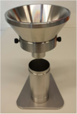
|
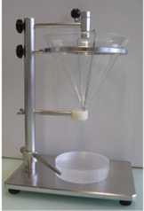
|
|
| (a) | (b) | (c) |
| ||
| (d) | ||
| Figure 7.1: Flowability methods used in this study. (a) Free-flow density cylinder. (b) Angle of repose apparatus. (c) GranuFall. (d) Revolution powder analyzer. Courtesy of Nestlé | ||
7.2.3 Experimental results
7.2.3.1 Carr Index and bulk density
Density measurements on powder samples allowed collecting compressibility data. Bulk densities and Carr indexes are summarized in Figure 7.2. For sucrose, is found to increase with particle size. A range from 500 g/L at small diameters to approximately 850g/L at larger diameter is observed in Figure 7.2. Samples with larger span tend to have larger bulk densities as demonstrated by the sample S1S3 (outlier at 280 ). follows a 1/x trend and reaches the value of 7 at large diameters which corresponds to good flowability according to literature [228]. Then, the compressibility value starts to increase around 250 and reaches the maximum value of 30, which corresponds to poor flow.
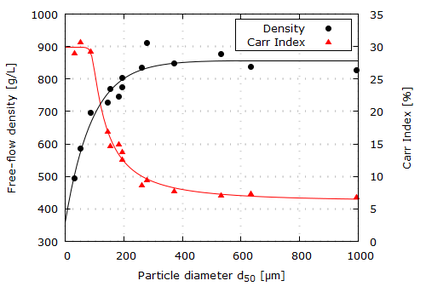
|
| Figure 7.2: Free-flow density and Carr Index results. Black and red solid lines are guides to the eye, respectively for density and Carr Index. Courtesy of Nestlé. |
| Reference name | Carr Index | Bulk density [g/L] |
| S1 | 7.1 | 877 |
| 6.8 | 826 | |
| 7.4 | 838 | |
| 7.8 | 848 | |
| S2 | 15 | 746 |
| S3 | 12.6 | 804 |
| 8.7 | 834 | |
| 14.7 | 768 | |
| S4 | 30.7 | 585 |
| 16.9 | 727 | |
| 29 | 494 | |
| S1S3 | 9.4 | 912 |
| S2S3 | 13.8 | 775 |
| S1S4 | 29.2 | 695 |
7.2.3.2 Angle of repose
The values of the angle of repose (AR) measured for sugars are summarized in Figure 7.3, where the angle is plotted as a function of the particle size (represented here with ). It is observed that the smaller the particle size, the higher the angle of repose. A plateau-like part appears at large diameters around 35, which correspond to a good flowability according literature [229], while a strong increase of the AR is observed at small diameters. The increase starts around 250-350 and leads to 55 at the smallest diameters, corresponding to poor flow.
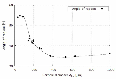
|
| Figure 7.3: Angle of repose results. Dashed lines are guides to the eye. Courtesy of Nestlé. |
7.2.3.3 GranuFall
GranuFall experiments for sugar powders are summarized in Figure 7.4. We plot and as a function of the particle size . It is observed that the powder does not flow for fine powders while the flow suddenly steps up to 70 mL/s around =200 before slowly diminishing down to 60 mL/s at larger diameters. One outlier with smaller flow is observed (sample S1S3), the same than in the density graph. Measurements of the critical diameter for flow show an opposite behavior. For fines, is larger than 34 mm (represented by an arbitrary point at 36 mm since powder did not flow at the maximum available hole diameter). Then, decreases with particle size probably reaching a minimum value below 4 mm which could not be determined with the apparatus (4 mm is the minimum available hole diameter).
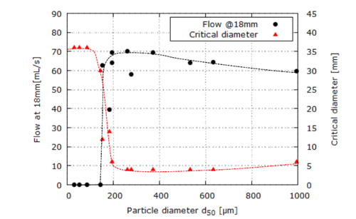
|
| Figure 7.4: GranuFall measurements on sugar powders. Flow at 18 mm diameter and minimum diameter to flow, versus particle size . Dashed lines are guides to the eye. Courtesy of Nestlé. |
7.2.3.4 Revolution Powder Analyzer
Finally, the last technique for flow characterization allowed obtaining the results presented in Figure 7.5. In this case, the results are presented in terms of angle of avalanche , corresponding to the angle between the powder-air interface and the horizontal plane before the avalanche occurrence, and the rest angle, measured immediately after the avalanche. Typically, varies from 30 to 100, from free flow to very poor flow. By observing Figure 7.5, in the case of sucrose, it is evident that both the avalanche and the rest angle are strongly influenced by the particle size below 300 ; while above this critical value a plateau-like trend is noted for both the parameters under study.
In Table 7.3, the main experimental results in term of angle of repose, flow rate and avalanche angle are resumed. All the data are listed in descending order of .
| Reference name | Angle of repose [] | flow rate | Avalanche angle [] | |
| 994.4 | 36.1 | 59.55 | 41.2 | |
| 632.9 | 34.8 | 64.55 | 40.7 | |
| S1 | 532.8 | 34.4 | 64.00 | 39.4 |
| 372.3 | 35.0 | 69.35 | 40.8 | |
| S1S3 | 279.3 | 38.5 | 57.90 | 43.6 |
| 260.8 | 38.8 | 70.05 | 40.0 | |
| S2S3 | 194.6 | 42.6 | 69.45 | 54.7 |
| S3 | 193.9 | 42.3 | 64.15 | 51.3 |
| S2 | 182 | 41.3 | 39.55 | 57.3 |
| 154.1 | 43.5 | 62.65 | 55.7 | |
| 145.5 | 42.5 | 0.00 | 61.2 | |
| S1S4 | 86.1 | 54.1 | 0.00 | 67.1 |
| S4 | 53.6 | 54.7 | 0.00 | 69.1 |
| 31.8 | 53.8 | 0.00 | 61.8 |
7.3 Numerical study
As it can be observed in Section 7.2, the experimental results of the laboratory tests, performed for the assessment of the flow performance of sucrose, show a strong relation with the particle size. A clear trend is outlined: decreasing the size of particles, the flow quality tends to be more poor. In a continuum mechanics approach, using a standard Mohr-Coulomb law (see Chapter 3), the set of material parameters needed does not include micro-scale parameters, such as, e.g., the particle size. In the validation study, macro-parameters are considered, instead, and used for the numerical investigation of flowability properties of different types of sugar.
It is observed that represents a critical value which markedly characterizes the flowability properties of sucrose. In this respect, in Table 7.3 a classification of the experimental results can be found; three groups are individuated depending on whether the corresponding is above (CASE 1), around (CASE 2) or below (CASE 3) the value of . The classification is made by considering only those samples showing the behaviour in line with the previously observed trends. For this reason, the outliers are not taken into account. In what follows, the groups, listed in Table 7.3, are used as guideline to the numerical study of the different behaviours observed.
| CASE | Bulk density | Repose angle |
| ||||
| CASE 1 | |||||||
| CASE 2 | |||||||
| CASE 3 |
Bulk density, (Figure 7.2), angle of repose (Figure 7.3) and angle of avalanche (Figure 7.5) are monotonic with . The flow through the orifice with a diameter of 18 mm (Figure 7.4) is monotonic with , as well. However, it can be seen that the evolution of the flow rate looks like a step-wise function, varying between 0 mL/s for values of below and 70 mL/s for values of just above the critical value of a few . In this regard, for example, by comparing the samples and , which have similar Particle Size Distribution, but a slightly different ( and , respectively), it is observed that in the first case while no flow occurs in the second one. There might be the possibility that, when , other parameters turn out to be leading factors in the determination of the flow rate in a flat bottom silo, such as, the or the particle shape. Thus, for a better understanding of the physical mechanisms and physical parameters which can determine the flowability of a certain granular material, further experimental tests should be planned and performed, as future work, which include other factors not considered in the current study. Moreover, since a remarkable difference is observed in the flow rate values for sugar samples with a close to , only the samples with a flow rate which ranges between and fall under CASE 2.
7.3.1 Numerical models
In this section, the computational models of angle of repose apparatus, GranuFall and Revolution Powder Analyzer, are presented. By referring to the description of the devises in Section 7.2.2, models which use axi-symmetry and plane strain assumptions are introduced. For the solution of the axisymmetric problem, the formulation presented in Appendix C is employed, while in the plane strain case, the formulation presented in Chapter 4 is considered.
7.3.1.1 Angle of repose
With respect to the angle of repose device, described in Section 7.2.2, the geometry of its numerical model is depicted in Figure 7.6a; while boundary conditions are depicted in Figure 7.6b where the fixed displacement along x-direction is represented in blue colour and in red the one along both x and y-directions. As it can be seen, the 3D geometry is reduced to a 2D axisymmetric model, in order to reduce the computational cost of the numerical simulation. The gray coloured area of Figure 7.6a refers to the domain initially occupied by the material points, while in yellow is the remaining area of the computational domain, where the particles are free to move. For the solution of this case an unstructured triangular mesh with element size of 1mm is adopted. The time step length can range between and , depending on the material properties adopted in each test case, and 6 material points are initially located in each element of the grid, which is found to be an optimal trade-off between accuracy of the results and computational cost.
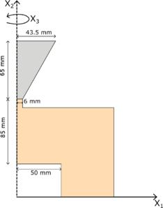
|
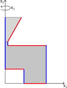
|
| (a) | (b) |
| Figure 7.6: Angle of repose apparatus: geometry (a) and boundary conditions (b) | |
This test is the most frequently used for different sizes and combinations of funneling methods (e.g., internal flow funnel and external flow funnel or a combination of both). In this case, with the method described in Section 7.2.3.2 it is measured the so-called external or poured angle of repose. In the literature, the angle of repose is often assumed to be equal to the residual internal friction angle or the constant volume angle in a critical state [230]. However, this assumption is valid under very restricted conditions and assumptions, as shown in [231], such as, uniform density, moisture content and particles size.
It is important to highlight that, in the experimental characterization, a device, which allows the measurement of both fluid and sticky powders, is employed. In the numerical analysis of cohesive powders, if the original geometry is adopted (see Figure 7.6a), with a very narrow outlet diameter, some phenomena of arching, which do not allow to complete the analysis, are observed. In order to overcome this aspect, the minimum diameter of the opening is found and used for the evaluation of the angle of repose.
7.3.1.2 GranuFall
In this section, the numerical model of the second device, used in the experimental study, is presented. By taking into consideration the description made in Section 7.2.2, the geometry is shown in Figure 7.7a; while the boundary conditions are depicted in Figure 7.7b where the fixed displacement along x-direction is represented in blue colour and in red the one along both x and y-directions. As done for the angle of repose model of Figure 7.6a, the 3D geometry is reduced to a 2D axisymmetric model. For the solution of this case an unstructured triangular mesh with element size of 1mm is adopted, the time step length can range between and , depending on the material properties adopted in each test case, and 6 material points are initially located in each element of the grid, which is found to be an optimal trade-off between accuracy of the results and computational cost.

|

|
| (a) | (b) |
| Figure 7.7: Granufall apparatus: geometry (a) and boundary conditions (b) | |
7.3.1.3 Revolution Powder Analyzer
Finally, the model of the Revolution Powder Analyzer is introduced. According to the description of the device in Section 7.2.2, the three-dimensional geometry is reduced to a 2D plane strain model, represented in Figure 7.8. The area coloured in gray refers to the domain initially occupied by the material points, while in yellow is the remaining area of the computational domain, where the particles are free to move. At the boundary of the rotating drum, prescribed displacement along the x and y direction ( and ) is applied in order to impose the rotational motion at an angular velocity of :
|
|
(7.1) |
with , and , where R is the radius of the drum and the distance between the point where the displacement is calculated (point P) and a reference point (point O), as depicted in Figure 7.8. For the solution of this case an unstructured triangular mesh with element size of 2mm is adopted, with a time step of and 6 material points are initially located in each element of the grid, which is found to be an optimal trade-off between accuracy of the results and computational cost.
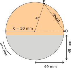
|
| Figure 7.8: Revolution Powder Analyzer: geometry. |
Depending on angular velocity, diameter of the cylinder, filling level, friction between particles and the wall, and particle material characteristics, different regimes of granular flow are observed which have been termed slipping, slumping, rolling, cascading, cataracting, and centrifuging (see Figure 7.9). Except for slipping where the granulate assumes a solid state and slides against the wall, these regimes can be observed in dependence on rotation velocity while all other parameters are fixed. For low angular velocity, as in the present case, the flow is non-stationary in a slumping mode. Accordingly, the free surface of the granulate forms a plane whose tilt fluctuates between the avalanche angle and the rest angle, e.g., between the state of maximum and minimum potential energy, respectively.
![Modes of motion in a Revolution Powder Analyzer[232].](/wd/images/thumb/2/2e/Draft_Samper_987121664-monograph-rotating_drum_modes.png/468px-Draft_Samper_987121664-monograph-rotating_drum_modes.png)
|
| Figure 7.9: Modes of motion in a Revolution Powder Analyzer [232]. |
7.3.2 Numerical results
In this section, a validation study is presented by comparing the numerical and experimental results in terms of angle of repose, flow rate and avalanche angle, for CASE 1, CASE 2 and CASE 3. The problem is solved at the macroscale and a study of the influence of the Mohr-Coulomb parameters, such as, the internal friction angle , the dilatancy angle and the apparent cohesion , on the sugar flowability performance is provided according to the classification previously performed. The internal friction angle describes the bulk friction during the incipient flow of a powder and it is determined from the linearised yield locus, as shown in Figure 3.2; while the apparent cohesion is the intercept from the linearised yield locus and it represents the strength of a powder under zero confining pressure. Even if these material parameters are representative of the behaviour of the bulk, in reality, they can be related to micro-scale parameters, such as, the inter-particle friction and the inter-particle cohesion, respectively. It is known that the inter-particle friction is due to the interlocking generated by the shape of the particles and the surface roughness; while the inter-particle cohesion, in the case of dry powder, is due to the van der Waals forces [233]. The dilatancy is representative of the volume change of a granular material when it undergoes a shear deformation, before reaching the critical state. If the material is compacted, the grains are interlocked and do not have the freedom to move; however, when the sample is stressed, a lever motion occurs between the particles in contact and a bulk expansion of the material is generated.
Since all the experimental results are single-valued function of , the particle size corresponding to 50% of the sample's mass sieved, a classification is made according to this parameter. CASE 1 corresponds to samples with the highest values of , typical of the common granulated sugar type. On the other hand, much lower values of fall under CASE 3 and these samples are associated with a powdered sugar type. Finally, with CASE 2 the case of transition, where flowability properties of sucrose drastically deteriorate in the transition from CASE 1 to CASE 3, is individuated.
In what follows, only the influence of the internal friction angle, dilatancy angle and apparent cohesion, is investigated. The ranges of bulk density value are provided by the experimental results (see Table 7.2), while other material parameters, such as, the Young modulus and Poisson's ratio, are considered to be the same in all three cases. Their values have been found in the literature [234].
7.3.2.1 Case 1: d₅₀ > 200 μm
CASE 1 represents all those samples which are characterized by a much higher than . The granular material, object of study, is in dry condition and in this case the amount of fine particles is so low that cohesive forces do not appear, and the bulk behaviour results to be totally cohesionless [234]. Thus, a zero apparent cohesion is used in all the investigated scenarios. On the other hand, internal friction angle and dilatancy angle may play a role in the flowability performance. In this regards, different cases have been investigated varying the values of and . For CASE 1, a bulk density value of , for all the scenarios to be investigated, is chosen following the classification made in Table 7.4.
The first experimental test to be analysed is the GranuFall test. Different values of and are considered: the internal friction angle ranges between and , while the dilatancy angle between and . In Figure 7.10 it can be observed that by increasing the dilatancy angle by a few degrees, the flow rate through an orifice of 18mm drastically decreases. In particular, it is found that, for values of between and , values of volumetric flow rate in the range of the experimental measurements are computed. These latter ones are depicted by the dot lines (Figure 7.10), that, hereinafter, they are used to represent the inferior and superior limit of the experimental range, as indicated in Table 7.4.
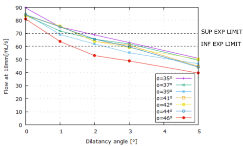
|
| Figure 7.10: Case 1. GranuFall test: volumetric flow. |
The second model to be investigated, in this validation study, is represented by the test of the angle of repose. The values of internal friction angle range between and ; while the values of dilatancy angle are constrained to the values of , and . In Figure 7.11, the results in terms of angle of repose are presented. In this case, it is found that the dilatancy angle has not an important influence on the results; while a remarkable difference is given by the internal friction angle. It is observed that to higher values of corresponds higher values of angle of repose and, as previously discussed, it is found that the angle of repose does not coincide with the values of internal friction angle. Further, it is seen that the numerical values are close to the experimental ones, depicted by the dot lines, representing the inferior and superior limit, as indicated in Table 7.4, when the value of ranges between and .
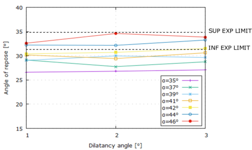
|
| Figure 7.11: Case 1. Angle of repose test: angle of repose. |
The last test is represented by the Revolution Powder Analyzer, described in Section 7.3.1.3. In this case, only the scenarios with a dilatancy angle of , and and an internal friction angle which ranges between and are considered. The results in terms of avalanche and rest angle are shown in Figures 7.12a and 7.12b, respectively. It is found that the internal friction angle has some influence on the avalanche angle, while it is not observed a strong relation with the rest angle, since, in all the scenarios investigated, the value falls in a very narrow range: between and . With regards to the dilatancy angle, this parameters has less influence than the internal friction angle on the numerical results. Thus, for the range of under study it is not possible to define any relation.
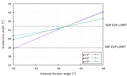
|
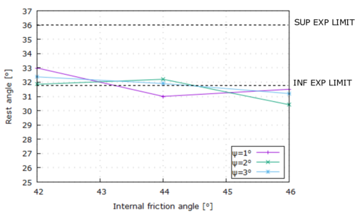
|
| (a) | (b) |
| Figure 7.12: Case 1. Revolution Powder Analyzer: avalanche angle results (a) and rest angle results (b) | |
By looking at the results obtained with the three different models, the set of material parameters, which provide numerical results which fall into the range of the experimental data for CASE 1, is found and listed in Table 7.5
|
|
Density |
|
|
Cohesion | ||||||||
| 1e6 Pa | 0.3 | 830 kg/mc | 44 deg | 2-3 deg | 0 Pa |
In what follows, the results obtained by using the set of material parameters of Table 7.5 are shown. In Figures 7.13a, 7.13b and 7.13c the repose angle, the avalanche and the rest angle, evaluated in the Revolution Powder Analyzer, are depicted. It can be noted that the surfaces of the heap formed by the angle of repose of Figure 7.13a and the material at rest after the avalanche of Figure 7.13c are very smooth. With respect to the Revolution Powder Analyzer, an avalanching shear layer is interacting with a quasi-static region. In Figure 7.14, it is possible to observe that the surface flowing layer has a reduced depth in comparison to the quasi-static one, and, consequently, the mass moving during the collapse, as well.
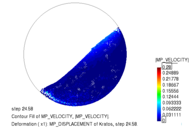
|
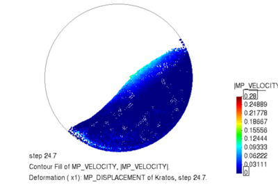
|
| (a) t=24.6s | (b) t=24.7s |
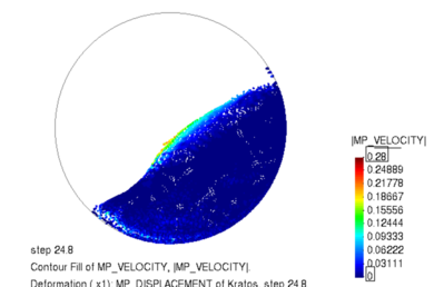
|
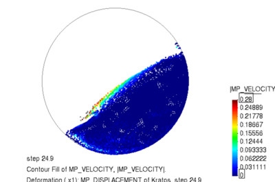
|
| (c) t=24.8s | (d) t=24.9s |
| Figure 7.14: Case 1. Revolution Powder Analyzer: velocity field at different time instants. | |
7.3.2.2 Case 2: d₅₀ ≃200 [μm]
CASE 2 represents the transition between CASE 1 and CASE 3, where the first signs of degradation of the flowability performance are observed. As it is observed in the experimental characterization, described in Section 7.2, these types of sugar are characterized by a median particle size, , which is around the critical value of . In this case, it is assumed that the internal friction angle is still a material parameter which can affect the material behaviour; on the other hand, unlike CASE 1, a zero dilatancy angle is considered due to the reduced particle size (as shown in [234]). Moreover, a reduction of the particle size generates an increase of inter-particle cohesion and, consequently, of the apparent cohesion [233]. Thus, is included in the set of parameters of the numerical study. For CASE 2, a bulk density value of , for all the scenarios to be investigated, is chosen following the classification made in Table 7.4. With respect to the internal friction angle and the apparent cohesion, the ranges and are considered, respectively.
The first model, object of study, is the GranuFall test. Different scenarios are analysed and the numerical results in terms of volumetric flow are shown in Figure 7.15. In this case, only the results, which fall into the range defined by the experimental measurements, are depicted. As can be observed, the greater the apparent cohesion, the lower the volumetric flow. Moreover, increasing the internal friction angle, the curve which describes the relation between the volumetric flow and the apparent cohesion, is shifted to the left part of the chart. Namely, this result represents the competition between the inter-particle cohesion and the inter-particle friction in the bulk friction behaviour of those samples which belong to CASE 2.
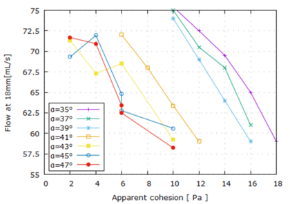
|
| Figure 7.15: Case 2. GranuFall test: volumetric flow. |
The same competition between the internal friction angle and the apparent cohesion is observed in Figure 7.16, where the results of the angle of repose test, which fall in the range of the experimental data, are shown. It is found that the value of the angle of repose is affected by both and : it increases when higher values of and are adopted. Unlike CASE 1, in this case it has been necessary to modify the model, described in Section 7.3.1.1, in order to avoid phenomena of arching, which do not allow to complete the analyses. In CASE 2, a variation of the opening diameter of a few is made, with the aim of reproducing the same dynamics during the pouring of the granular material, as in the experimental test.
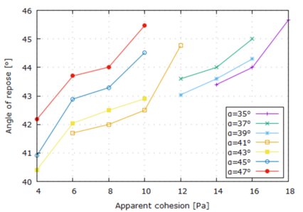
|
| Figure 7.16: Case 2. Angle of repose test: angle of repose. |
Finally, the model of Revolution Powder Analyzer is analysed. The results in terms of avalanche and rest angle are shown in Figures 7.17a and 7.17b, respectively. It is found that higher avalanche angles correspond to higher values of internal friction angle and apparent cohesion. Moreover, these results linearly depends on the apparent cohesion and the angular coefficient increases with the . The same observations can be done concerning the rest angle. In both the charts of Figure 7.17, one can note that the same final results can be achieved with different sets of and . Indeed, in this case there is not a unique set of material parameters which allows to predict the experimental data, but rather two sets are individuated and they are listed in Table 7.6.
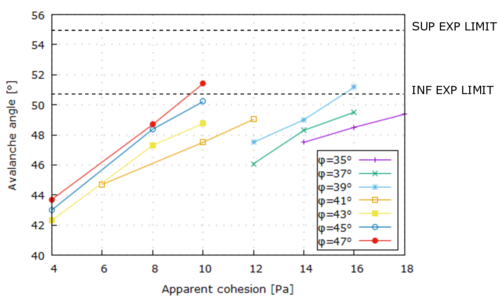
|
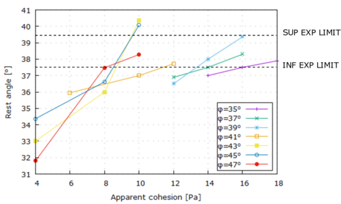
|
| (a) | (b) |
| Figure 7.17: Case 2. Revolution Powder Analyzer: avalanche angle results (a) and rest angle results (b) | |
|
|
Density |
|
|
Cohesion | ||||||||
| 1e6 Pa | 0.3 | 740 kg/mc | 39 deg | 0 deg | 16 Pa | ||||||||
| 1e6 Pa | 0.3 | 740 kg/mc | 47 deg | 0 deg | 10 Pa |
In addition, the numerical results obtained with an internal friction angle of and an apparent cohesion of are shown in Figures 7.18a, 7.18b and 7.18c, where the angle of repose, the avalanche and rest angle, evaluated in the Revolution Powder Analyzer, are represented. It can be observed that the surface smoothness in Figure 7.18a is retained; indeed, it is quite evident and easy to recognize the angle of repose, formed by the heap. On the other hand, in Figure 7.18c the surface is not completely smooth due to the cohesive behaviour shown in CASE 2. In addition, with respect to the Revolution Powder Analyzer, by observing Figure 7.19 the depth of the avalanching shear layer has increased, along with the amount of mass which is flowing during the collapse.
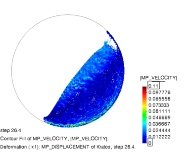
|
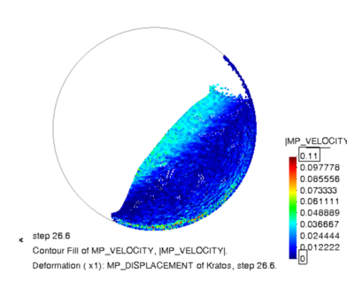
|
| (a) t=26.4s | (b) t=26.6s |
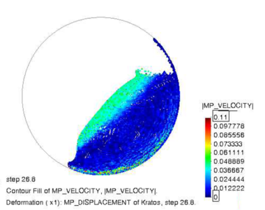
|
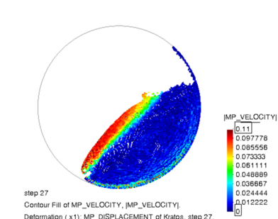
|
| (c) t=26.8s | (d) t=27s |
| Figure 7.19: Case 2: Results of rotating drum test. Velocity field at different time instants. | |
7.3.2.3 Case 3: d₅₀ < 200 μm
CASE 3 is representative of all those samples which show a very poor flowability performance. These granular materials are characterized by a and by a high amount of fine particles, which make them very sticky and cohesive. When the particles are small, the inter-particle cohesion dominates the flow behaviour and enhances the shear resistance. In addition, these dry cohesive interactions result in the formation of clusters, which generate many voids within the bulk, thus, at the macroscale, resulting in a low bulk density. If the bulk density is low, there are free spaces for the particles to move and the geometrical inter-locking does not play an important role in this case. For this reason, a zero dilatancy angle is considered due to the reduced particle size (as shown in [234]). On the other hand, several scenarios are investigated where a different set of internal friction angle and apparent cohesion are considered. For CASE 3, a bulk density value of , for all the scenarios to be investigated, is chosen in accordance with the classification made in Table 7.4. With respect to the internal friction angle and apparent cohesion, values which range between and are considered, respectively.
As done already in the previous cases, the first test case to be considered is the GranuFall test. According to the experimental results listed in Table 7.3, in this case no volumetric flow takes place. In this regard, from the numerical simulation it is observed that the minimum value of apparent cohesion for which no flow is observed corresponds to . With regard to the internal friction angle, no influence is noted in the numerical solutions.
The second model, under study, is represented by the angle of repose test. In this case, the value of apparent cohesion is high enough that it is not possible to perform the simulation with the original model, described in Section 7.3.1.1. This is due to the fact that the material is very cohesive and the opening diameter is too narrow in order to see the material starting flowing. In the simulation of this case, the diameter has to be increased of several times its original dimension; however, it is observed that the material is flowing down at a very high velocity generating a mismatch with the dynamics, which have taken place during the experimental test. This can create a variation in the final numerical solution and, for this reason, it is decided that the results obtained from this model are not reliable and representative of the physical process, and, consequently, they are not included in this validation study.
Finally, the third model, to be considered, is the Revolution Powder Analyzer. In this case, the internal friction angle ranges between and , while the apparent cohesion between and . In Figures 7.20a and 7.20b the numerical results in terms of avalanche and rest angle are represented, respectively. With regard to the avalanche angle, it is seen that the internal friction angle has more influence in correspondence of lower values of cohesion; while the apparent cohesion has a strong influence in all the scenarios considered and a linear relation is observed, with an angular coefficient inversely proportional to the internal friction angle value. With respect to the rest angle, it seems that does not have any influence on the final results; on the other hand, a linear relation between the rest angle and the apparent cohesion is noted, with an angular coefficient common to all the investigated cases.
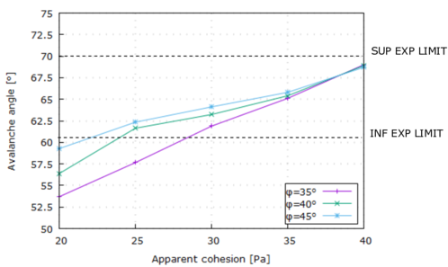
|
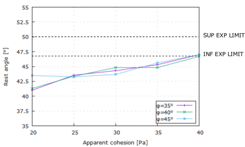
|
| (a) | (b) |
| Figure 7.20: Case 3. Revolution Powder Analyzer: avalanche angle results (a) and rest angle results (b) | |
As can be observed in Figure 7.20, the set of material parameters, which are able to provide results in the ranges defined by the experimental data, represented by the dot lines, are listed in Table 7.7. It is found that, in CASE 3, the behaviour of the samples are not affected by the internal friction angle, but are mostly influenced by the apparent cohesion.
|
|
Density |
|
|
Cohesion | ||||||||
| 1e6 Pa | 0.3 | 600 kg/mc | 35-45 deg | 0 deg | 40 Pa |
In what follows, the results obtained by using the set of material parameters of Table 7.7 are shown. In Figures 7.21a and 7.21b the avalanche and the rest angle, evaluated in the Revolution Powder Analyzer, are depicted. It can be noted that the results of CASE 3 are not characterized by the surface smoothness, observed in the previous cases, due to the sticky behaviour of the material. Moreover, in Figure 7.22 it is possible to observe a flowing layer with a depth comparable to the quasi-static one and a mass which is moving in a very cohesive way.
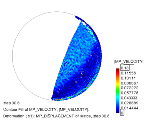
|
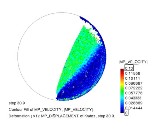
|
| (a) t=30.8s | (b) t=30.9s |
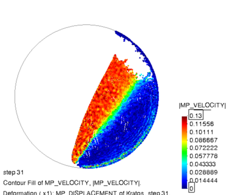
|
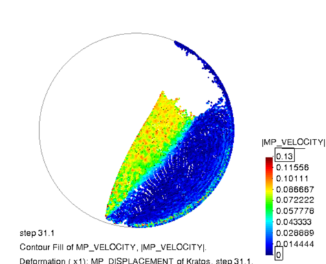
|
| (c) t=31s | (d) t=31.1s |
| Figure 7.22: Case 1: Results of rotating drum test. Velocity field at different time instants. | |
7.4 Discussion
In this Chapter, an application of the MPM strategy in the industrial framework is presented. The main aim of this study is the experimental and numerical characterization of flowability of different sugar powders. It is experimentally found that the flowability performance strictly depends on the particle size distribution, and, in particular, a strong relation with is shown. In the numerical study, a macroscopic approach is followed. The phenomenological Mohr-Coulomb plastic law is employed and the study is performed in order to find a correlation between the behaviour of different types of sugar and the macroscopic material parameters of internal friction angle, dilatancy angle and apparent cohesion. The numerical solutions have shown that, depending on the class of flowability, the bulk friction behaviour can be influenced by different parameters. In those samples characterized by a good flowability and high values of (CASE 1), it is numerically found that the parameters, which mainly affect the shear resistance, are represented by the internal friction angle and dilatancy angle; this is confirmed by those mechanisms which have been observed to take place at the microscale: the shear resistance is due to interlocking generated by the shape of the particles and their surface roughness. For those samples with very poor flowability and a sticky behaviour (CASE 3), a much lower than is experimentally estimated. In this case, it is numerically demonstrated that the apparent cohesion is the parameter which mostly governs the macroscopic behaviour of the material; while, at the microscale, due to the high amount of fine particles, cohesive forces appear between adjacent granules and, consequently, the inter-particle cohesion is the main mechanism in the shear resistance. In the case of transition (CASE 2), where the first signs of a deterioration of the flowability performance are visible, it is numerically observed that the results are affected in equal measure by the internal friction angle and apparent cohesion. This can be traduced, at the microscale, in a competition between inter-particle friction and inter-particle cohesion; this might be due to the presence of fine particles, even if their quantity is limited. In conclusion, all the numerical solutions, presented in the numerical study of Section 7.3, as demonstrated, are representative of the mechanisms which are observed to take place at the particle level and the observations made are representative and totally in line with the experimental results of Section 7.2.
8 Conclusions and future work
In this Chapter, the conclusions of the monograph are presented and an overview of the future lines of research is made.
8.1 Concluding remarks
The main aim of this work was the development of a numerical strategy for the simulation of quasi-static and dense granular flows in the industrial and engineering framework. These kinds of problems are characterized by a non-linear behaviour of the material and by large deformation of the continuum during the whole flow process. In order to perform a numerical investigation, a strategy, which is able to consider these non-linearities, is needed. It is found that, among all the numerical methods, mostly used for the solution of granular flows problems, the Material Point Method (MPM) is the one which has shown the most suited capabilities for the cases targeted to study in this monograph (Chapter 2). In the current work, an implicit MPM has been developed by the author in the multi-disciplinary Finite Element codes framework Kratos Multiphysics [29,30,31] and in order to obtain a verified and validated numerical strategy the following points have been performed (Chapters 3, 4, 5 and 6):
- Three phenomenological constitutive laws, implemented within the MPM numerical strategy, are introduced and their formulations are derived. In particular, a hyperelastic Neo-Hookean, a hyperelastic-plastic J2 and Mohr-Coulomb plastic laws, along with their limits of applicability, are discussed. All the constitutive materials are defined under the assumption of isotropy and finite strains. With the object of the current monograph in hand, the focus is mainly on the Mohr-Coulomb plastic law, where in this work, to the knowledge of the author, the return mapping is used for the first time under finite strain assumption. This phenomenological law is commonly adopted in the modelling of granular materials, since it shows a pressure-dependent behaviour. This constitutive law is used in the verification, validation and application of the MPM strategy.
- A variational displacement-based formulation, based on an Updated Lagrangian description, is presented and its derivation is described in detail. A verification of the MPM code is performed through some benchmark tests, typical in solid and geo-mechanics. Moreover, in the verification analysis, a comparison of the MPM code is done against the Galerkin Meshfree Method (GMM), a continuum particle-based technique. Since both the methods are implemented in the Kratos Multiphysics platform, it has been possible to perform a more objective comparison, which allows to better appreciate the main differences between these two techniques. In GMM the Eulerian background grid is replaced by a Lagrangian one and, unlike MPM, the shape functions are evaluated once the cloud of nodes of each material point is defined. The comparison is made with the aim of assessing the accuracy and robustness of the two methods in the simulation of cohesive-frictional materials, both in static and dynamic regimes and in problems dealing with large deformations. It is found that MPM leads to more accurate results and its robustness is proven. On the other hand, it is observed that the accuracy of GMM strictly depends on the choice of the basis functions and a modification of the algorithm has to be considered in large displacement cases. After this study, it is demonstrated that the MPM strategy represents a good choice to handle problems involving history-dependent materials and large deformations.
- A variational displacement and pressure-based formulation, based on an Updated Lagrangian description, is presented and its derivation is described in detail. The mixed formulation is developed with the aim of solving granular flow problems which undergo nearly-incompressible conditions. To the knowledge of the author, the treatment of the incompressibility constraint is relatively new in the context of MPM and this formulation represents an original solution among the works that one can find in the literature. A verification of the MPM code is performed through some benchmark tests, typical in solid mechanics. In the verification analysis, the results obtained through the mixed formulation are compared with those evaluated by means of the displacement-based one. As expected, it is noted that, in nearly-incompressible conditions, the typical issue of volumetric locking is overcome and pressure oscillations are avoided with the formulation. In addition, it is found that also in compressible cases the formulation provides more accurate results than the irreducible one. However, despite a higher accuracy in terms of displacement, equivalent plastic strains and vertical Cauchy stress fields, the mixed formulation, presented in this work, is not able to fix some other issues, such as, mesh independence and strain localization.
- The MPM strategy, developed in the Kratos Multiphysics platform, is employed to solve typical problems of geo-mechanics. Two problems are considered in the validation study: the first one is represented by the typical test of column collapse of a dry cohesionless granular material and the second one by the evaluation of the bearing capacity of an undrained soil in the rigid strip footing test. In the first case, the irreducible formulation is employed and the numerical results are compared against experimental results. Different geometries of the column are investigated. It is both experimentally and numerically observed that the dynamic of the collapse strictly depends on the initial geometry. It is seen that for lower aspect ratio the MPM code is able to provide results in agreement with the experimental ones. On the other hand, in the case of higher aspect ratio, the MPM strategy underestimates the dissipation which takes place during the collapse of the column. In this regard, the disagreement might be mostly due to the employed constitutive law: the Mohr-Coulomb plastic law adopted in the current work is not able to predict the real energy dissipation that should have taken place during the failure mechanism. Indeed, as indicated in some similar works available in the literature, the evolution of some factors, such as, density and dilatancy, which play important role in defining the first failure surface, and, hence, the total mass that will move, are not here considered. In the second test, the and formulations are both employed. It is observed that the mixed formulation is able to provide better results in terms of displacement and stress field. By sampling the computed stress field at the edge, where the imposed displacement of the rigid footing is applied, it has been possible to define the curve which describes the bearing capacity of the soil. This result is compared with a curve obtained from a sequential limit analysis and a good agreement is observed between the two solutions.
Finally, in Chapter 7 the MPM strategy is employed in an industrial framework, in the context of a collaboration with Nestlé. The numerical results are compared against unpublished experimental measurements performed for the assessment of the flowability performance of different types of sucrose. It is experimentally observed that the flowability performance is strictly dependent on the particle size distribution of the granular material and, in particular, on the median particle size . On the other hand, the numerical study is performed by following a macroscopic approach and the flowability is studied according to macro-parameters, such as, the internal friction angle, the dilatancy angle and the apparent cohesion. In this study, the MPM strategy has been successfully employed and the advantage of its usage, as a complementary tool for a better understanding of the granular flow process, is demonstrated.
8.2 Future work
From the observation made and the conclusions drawn, the future lines of research are provided. It has been demonstrated that the MPM is not only a robust numerical tool for the simulation of problems involving large displacement and large deformation, but it is also an optimal platform for the implementation of complex constitutive laws. In this work, it is observed that the implemented Mohr-Coulomb plastic law is not able to predict the real energy dissipation that should have taken place during the failure mechanism. In the context of material modelling, a research should be focused on implementing constitutive laws with features, able to improve the prediction in terms of triggering of the collapse and amount of energy dissipated during the flow process. During the PhD, a collaboration with the Multiscale Mechanics group (MSM, University of Twente), lead by Prof. Stefan Luding, has started with the aim of implementing in the MPM strategy framework an elastic isotropic micro-based constitutive model for granular materials. This constitutive law, valid under quasi-static/elastic regime, has been developed by the researchers of the MSM group [235,236,237,238,239], by performing a series of DEM simulations of isotropic compression and pure shear tests. By averaging some microscopic quantities, that can be directly retrieved from the DEM simulations, macro parameters like stress and fabric 1 tensors can be evaluated. Then, by applying the definition of bulk and shear moduli, their expressions as a function of micro parameters, such as the volume fraction, pressure and coordination number, are obtained. Thus, the elastic mechanical properties are not considered constant, as it is usually assumed in a phenomenological model, but they vary accordingly with the evolution of the micro-structure.
With regard to the numerical formulation, other mixed variational formulations, which allow to overcome the issues of mesh dependence and strain localization, can be considered to improve the accuracy of the results.
In addition, in this work the applicability of the developed MPM strategy is limited to the simulation of dry granular flows. Other applications, where MPM is still a suited choice, is represented by granular flows interacting with rigid or deformable structures. Some examples can be found in the field of environmental engineering, such as, landslides interacting with systems of protective barriers or the quantitative risk assessment in landslide prone-area. For the development of the numerical strategy, a coupling between the MPM code and a FEM code is needed. In this regard, a work, mainly focused on the imposition of boundary conditions and contact algorithm, is still missing. However, some promising results have been already done within the Kratos team and published in [240,241], where algorithms for the imposition of non-conforming boundary conditions and frictional contact are presented and tested.
Last but not least, the important aspect of parallelisation of the code, which is not addressed in the current monograph, has to be developed as future work. In the current state, the MPM strategy uses an OpenMP method, which is able to guarantee a sustainable computational cost for the simulation of real scale systems. However, in order to fully exploit the MPM capabilities and make the application competitive with other commercial and open-source software, a modification of the code in favour of a MPI parallelisation should be addressed.
(1) The fabric tensors is a tensor able to provide information which characterize the anisotropic architecture of the microstructure in a porous material
Appendix A. Plastic flow rule in finite strains regime
In this section a general plastic flow rule within the framework of multiplicative plasticity is defined and it is demonstrated that if the specific strain energy function is expressed in terms of Hencky strains it is possible to recover the small strains format return mapping [155]. In order to formulate a plastic flow rule in finite strains regime, it is convenient to introduce the kinematic quantities of rate of plastic deformation and the plastic spin tensor , defined as
|
|
(A.1) |
|
|
(A.2) |
where is the plastic part of the velocity gradient . Since is a kinematic variables defined in the intermediate configuration, it is useful to perform the following rotation of in order to express it in the spatial configuration:
|
|
(A.3) |
with is the orthogonal tensor used in the polar decomposition
|
|
(A.4) |
where is the left stretch tensor.
Given a general plastic potential defined in terms of the Kirchhoff stress tensor and the rate of the plastic multiplier , the evolution of the plastic deformation gradient is defined by the following constitutive equation:
|
|
(A.5) |
by postulating a zero plastic spin , which is compatible with the assumption of plastic isotropy. With Equation A.3 in hand and the following property , it is possible to rewrite the evolution equation as
|
|
(A.6) |
In the definition of the plastic problem an isotropic perfectly plastic constitutive model is assumed. In this regard, the model is defined by postulating
- a specific strain energy function , from which the hyperelastic law is derived;
- a yield function which defines when plastic flow starts;
- a plastic potential , from which the plastic flow rule is derived.
Thus, the basic constitutive initial value problem states: given an initial value of at and the history of the deformation gradient for , find the functions and which satisfy the flow rule
|
|
(A.7) |
and the Kuhn-Tucker loading/unloading conditions
|
|
(A.8) |
with the yield function and defined as
|
|
(A.9) |
where is the elastic Hencky strain.
The algorithmic procedure to be established in order to solve the plastic problem is based on the discrete form of the evolution equation (see Equation A.7). Accordingly, a time stepping algorithm is performed by applying a backward exponential integrator on Equation A.7, which leads to the updated formula for the plastic deformation gradient:
|
|
(A.10) |
Equation A.10 can be written in terms of the current elastic deformation gradient as follows
|
|
(A.11) |
where the expressions of the incremental deformation gradient and Equation 3.53 are employed.
In what follows, few steps are performed in order to express Equation A.11 in terms of Hencky strains and it is demonstrated that the final form has the same format of the elastic strain update formula of the return mapping algorithm defined under the assumption of infinitesimal strains [155].
By post-multiplying Equation A.11 by
|
|
(A.12) |
and moving the exponential to the left side of the equation
|
|
(A.13) |
Equation A.13 is, then, multiplied on both sides by its transpose
|
|
(A.14) |
and by rearranging the terms in Equation A.14 and taking the square root of it gives
|
|
(A.15) |
The final form is obtained by applying the tensor logarithm on both side of Equation A.15
|
|
(A.16) |
In conclusion, Equation A.16 represents the Hencky strain updated formula of the return mapping in finite strains.
Appendix B. Derivatives of the rank-one matrices principal direction
In this section the expression of the spatial form of is derived
|
|
(B.1) |
where and denote the eigenvectors and eigenbases associated with the eigenvalues of the left Cauchy-Green deformation tensor , respectively, and , the metric tensor in the current configuration. In order to find the expression of the closed-form, firstly, the relation of Equation B.1 is transformed in material description by operating a pull-back transformation
|
|
(B.2) |
with being the right Cauchy-Green strain tensor and the eigenbases associated to . The spectral decomposition of the right Cauchy-Green strain tensor which reads
|
|
(B.3) |
where and denotes eigenvalues and associated eigenvectors, is considered and from Serrin's representation [242] it is possible to express in a closed-form in terms of as
|
|
(B.4) |
where and are the first and third principal invariants of . From Equation B.4 it follows that the expression of reads
|
|
(B.5) |
With the expression of in hand, its derivative with respect to is
|
|
(B.6) |
In order to obtain the final expression the following relations have been used:
|
|
(B.7) |
|
|
(B.8) |
|
|
(B.9) |
|
|
(B.10) |
By performing a push-forward operation on the final result of Equation B.6, it is possible to obtain its spatial counterpart
|
|
(B.11) |
Appendix C. Irreducible formulation in axisymmetric problems
In this section the matrix formulation for an axi-symmetrical finite element, undergoing finite deformations with respect to the spatial configuration, is presented.
This formulation can be used in the case of 3D bodies, which have rotational symmetry, as depicted on the left side of Figure C.1, and, thus, can be reduced to a 2D axi-symmetrical model, right side of the picture.
Hereinafter, it is assumed that the axis of symmetry coincides with the coordinate .
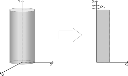
|
| Figure C.1: Axisymmetric representation of a 3D body with rotational symmetry. |
Additionally, to the strains in the plane , hoop strains (along direction) occur in case of axi-symmetrical deformations. The deformation gradient, is, then, given, as:
|
|
(C.1) |
By using linear shape functions, the symmetric gradient of the test functions reads
|
|
(C.2) |
and this leads to , the deformation matrix relative to node , expressed here for a 2D axis-symmetrical problem as:
|
|
(C.3) |
Introduction of the Cauchy stress, written in a vector form , and multiplied by , expressed by Equation C.2 leads to
|
|
(C.4) |
By using the results of Equation C.4, the virtual internal work of one element is
|
|
(C.5) |
It is observed that the integration has to be performed over the coordinates and as in circumferential direction. Due to that, the coordinate appears in Equation C.5. For the node of element the residual is defined as
|
|
(C.6) |
and its linearization yields to the tangent matrix, sum of the geometric and material stiffness matrix, expressed as in Equation 4.35.
The geometric stiffness matrix, whose definition is expressed by the first term of the integral of Equation 4.25, in its discretized form reads
|
|
(C.7) |
where and are the indexes of the finite element's nodes, is the spatial gradient of the shape function evaluated at node , is the volume relative to a single material point.
In case of axi-symmetrical deformations, matrix form of the gradient of the test function takes the form:
|
|
(C.8) |
Using this relation of Equation C.8, together with the expression of the Cauchy stress in the following matricial form:
|
|
(C.9) |
the geometric stiffness matrix in discretized form can be written as
|
|
(C.10) |
As explained in [243], it is possible to defined the term in an explicit way as follows:
|
|
(C.11) |
if the terms
|
|
(C.12) |
|
|
(C.13) |
|
|
(C.14) |
are employed.
With respect to the material stiffness matrix, the discretized form of the 3D case is expressed by Equation 4.34. In the case of axi-symmetrical deformations, its expression reads
|
|
(C.15) |
by taking into account the relations of (Equation C.3) and , matrix form of the incremental constitutive tensor of Equation 4.24 for axi-symmetric case.
Finally, by considering the contribution of the terms and , the tangent stiffness matrix , referred to the spatial configuration, can be expressed as follows:
|
|
(C.16) |
BIBLIOGRAPHY
[1] Avi, L. and Ooi, J. Y. (2011) "Discrete element simulation: challenges in application and model calibration", Volume 13. Granular Matter 2 107–107
[2] Utili, S. (2015) "International Symposium on Geohazards and Geomechanics (ISGG2015)", Volume 26. IOP Conference Series: Earth and Environmental Science 1 011001
[3] Nakagawa, M. and Luding, S. (2009) "Powders and grains 2009: Proceedings of the 6th international conference on micromechanics of granular media", Volume 1145. American Institute of Physics Conference Series
[4] Yu, A. and Dong, K. and Yang, R. and Luding, S. (2013) "Powders and Grains 2013: Proceedings of the 7th International Conference on Micromechanics of Granular Media", Volume 1542. In American Institute of Physics Conference Series
[5] Luding, S. and Tomas, J. (2014) "Particles, contacts, bulk-behavior", Volume 16. Granular Matter 3 279–280
[6] Wu, C.Y. and T. Pöschel. (2013) "Micro-mechanics and dynamics of cohesive particle systems", Volume 15. Granular Matter 389–390
[7] E.W. Merrow. (1988) "Estimating the startup times for solid processing plants", Volume 95. Chem. Eng. 15 89-92
[8] B. J. Ennis and J. Green and R. Davies. (1994) "The legacy of neglect in the U.S.", Volume 90. Chem. Eng. Prog. 32 - 43
[9] H. J. Feise. (2003) "Industrial perspective on the future of solids processing", Volume 81. Chemical Engineering Research and Design 837 - 841
[10] Haff, P. K. (1983) "Grain flow as a fluid-mechanical phenomenon", Volume 134. Journal of Fluid Mechanics -1 401
[11] Campbell, C. S. (2006) "Granular material flows - An overview", Volume 162. Powder Technology 3 208 - 229
[12] Bathurst, R.J. and Rothenburg, L.L. (1988) "Micromechanical Aspects of Isotropic Granular Assemblies With Linear Contact Interactions", Volume 55. ASME. J. Appl. Mech. 1 17 - 23
[13] Goddard, J. D. (1990) "Nonlinear Elasticity and Pressure-Dependent Wave Speeds in Granular Media", Volume 430. Proceedings: Mathematical and Physical Sciences 1878 105 - 131
[14] J. Duffy and R. D. Mindlin. (1957) "Stress-strain relations and vibrations of a granular medium", Volume 24. J. Appl. Mech. 585 - 593
[15] Bagnold, R.A. (1954) "Experiments on a Gravity-Free Dispersion of Large Solid Spheres in a Newtonian Fluid under Shear", Volume 225. Proceedings of the Royal Society A: Mathematical, Physical and Engineering Sciences 1160 49–63
[16] Goldhirsch, I. (2003) "RAPID GRANULAR FLOWS", Volume 35. Annual Review of Fluid Mechanics 1 267-293
[17] H.P. Zhu and Y.H. Wu and A.B. Yu. (2005) "Discrete and continuum modelling of granular flow", Volume 3. China Particuology 6 354 - 363
[18] Nedderman, R. M. (1992) "Statics and Kinematics of Granular Materials". Cambridge University Press
[19] P. Jop and Y. Forterre and O. Pouliquen. (2006) "A constitutive law for dense granular flows", Volume 441. Nature 7094 727 - 730
[20] Vescovi, D. and Luding, S. (2016) "Merging fluid and solid granular behavior", Volume 12. Soft Matter 8616-8628
[21] Chialvo, S. and Sun, J. and Sundaresan, S. (2012) "Bridging the rheology of granular flows in three regimes", Volume 85. American Physical Society. Phys. Rev. E 021305
[22] Kamrin, K. and Koval, G. (2012) "Nonlocal Constitutive Relation for Steady Granular Flow", Volume 108. American Physical Society. Phys. Rev. Lett. 178301
[23] Singh, A. and Magnanimo, V. and Saitoh, K. and Luding, S. (2015) "The role of gravity or pressure and contact stiffness in granular rheology", Volume 17. New journal of physics 4 043028
[24] P. A. Cundall and O. D. L. Strack. (1979) "A discrete numerical model for granular assemblies", Volume 29. Géotechnique 1 47-65
[25] Ramkrishna, D. (2000) "Population Balances: Theory and Applications to Particulate Systems in Engineering". Academic press
[26] Austin, L.G. (1971) "Introduction to the mathematical description of grinding as a rate process", Volume 5. Powder Technology 1 1 - 17
[27] Herbst, J.A. and Fuerstenau, D.W. (1980) "Scale-up procedure for continuous grinding mill design using population balance models", Volume 7. International Journal of Mineral Processing 1 1 - 31
[28] Sulsky, D. and Zhou, S.-J. and Schreyer, H. L. (1995) "Application of a particle-in-cell method to solid mechanics", Volume 87. Computer Physics Communications 1-2 236–252
[29] P. Dadvand. (2007) "A framework for developing finite element codes for multi-disciplinary applications.". PhD thesis: Universidad Politécnica de Cataluña
[30] P. Dadvand and R. Rossi and E. Oñate. (2010) "An object-oriented environment for developing finite element codes for multi-disciplinary applications", Volume 17. Archives of Computational Methods in Engineering 253-297
[31] Dadvand, P. and Rossi, R and Gil, M. and Martorell, X. and Cotela, J. and Juanpere, E. and Idelsohn, S.R. and Oñate, E. (2011) "Migration of a Generic Multi-Physics Framework to HPC Environments". Barcelona Supercomputing Center. Proceedings of the 23rd International Conference on Parallel Computational Fluid Dynamics
[32] Donea, J. and Giuliani, S. and Halleux, J.-P. (1982) "An arbitrary Lagrangian-Eulerian finite element method for transient dynamic fluid-structure interactions", Volume 33. Elsevier. Computer methods in applied mechanics and engineering 1-3 689–723
[33] Li, S. and Liu, W.K. (2002) "Meshfree and particle methods and their applications", Volume 55. Applied Mechanics Review 54 1-34
[34] Gröger, T. and Katterfeld, A. (2006) "On the numerical calibration of discrete element models for the simulation of bulk solids", Volume 21. 16th European Symposium on Computer Aided Process Engineering and 9th International Symposium on Process Systems Engineering. Elsevier 533 - 538
[35] Luding, S. (2008) "Introduction to discrete element methods", Volume 12. Taylor Francis. European Journal of Environmental and Civil Engineering 7-8 785-826
[36] P. W. Cleary. (2009) "Industrial particle flow modelling using discrete element method", Volume 26. Engineering Computations 6 698-743
[37] Labra, C. and Rojek, J. and Oñate, E. and Zarate, F. (2008) "Advances in discrete element modelling of underground excavations", Volume 3. Acta Geotechnica 317–322
[38] Casas, G. and Mukherjee, D. and Celigueta, M.A. and Zohdi, T. and Oñate, E. (2017) "A modular, partitioned, discrete element framework for industrial grain distribution systems with rotating machinery", Volume 4. Computer Methods in Applied Mechanics and Engineering 181–198
[39] Guo, Y. and Curtis, J. S. (2015) "Discrete Element Method Simulations for Complex Granular Flows", Volume 47. Annual Review of Fluid Mechanics 1 21-46
[40] J. F. Favier and M. H. Abbaspour-Fard and M. Kremmer. (2001) "Modeling Nonspherical Particles Using Multisphere Discrete Elements", Volume 127. Journal of Engineering Mechanics 10 971-977
[41] Azéma, E. and Radjaï, F. and Peyroux, R. and Richefeu, V. and Saussine, G. (2008) "Short-time dynamics of a packing of polyhedral grains under horizontal vibrations", Volume 26. Springer. The European Physical Journal E 3 327–335
[42] Podlozhnyuk, A. and Pirker, S. and Kloss, C. (2017) "Efficient implementation of superquadric particles in Discrete Element Method within an open-source framework", Volume 4. Computational Particle Mechanics 1 101–118
[43] Luding, S. (1998) "Collisions and Contacts between Two Particles", Volume 350. Springer. Physics of Dry Granular Media. NATO ASI Series (Series E: Applied Sciences)
[44] Walton, O. R. and Johnson, S. M. (2009) "Simulating the Effects of Interparticle Cohesion in Micron-Scale Powders", Volume 1145. AIP Conference Proceedings 1 897-900
[45] Thakur, S.C. and Morrissey, J.P. and Sun, J. and Chen, J.F. and Ooi, J.Y. (2014) "Micromechanical analysis of cohesive granular materials using the discrete element method with an adhesive elasto-plastic contact model", Volume 16. Granular Matter
[46] Walton, O.R. (1993) "Particulate Two-Phase Flow". Butterworth-Heinemann
[47] Brilliantov, N.V. and Spahn, F. and Hertzsch, J.M. and Poschel T. (1996) "Model for collisions in granular gases", Volume 53. Physical review E 5392
[48] Thornton, C. and Ning, Z. (1998) "A theoretical model for the stick/bounce behaviour of adhesive, elastic-plastic spheres", Volume 99. Powder Technology 2 154 - 162
[49] Lucy, L. B. (1977) "A numerical approach to the testing of the fission hypothesis", Volume 82. The Astronomical Journal 1013-1024
[50] Gingold, R.A. and Monaghan, J.J. (1977) "Smoothed particle hydrodynamics-theory and application to non-spherical stars", Volume 181. Monthly Notices of the Royal Astronomical Society 375–389
[51] Monaghan, J.J. (2005) "Smoothed particle hydrodynamics", Volume 68. Reports on Progress in Physics 8 1703–1759
[52] Dalrymple, R.A. and Rogers, B.D. (2006) "Numerical modeling of water waves with the SPH method", Volume 53. Elsevier. Coastal engineering 2 141–147
[53] Hultman, J. and Pharayn, A. (1999) "Hierarchical, dissipative formation of elliptical galaxies: Is thermal instability the key mechanism? Hydrodynamical simulations including supernova feedback multi-phase gas and metal enrichment in CDM: Structure and dynamics of elliptical galaxies", Volume 347. Astron. Astrophys. 769 - 798
[54] Monaghan, J.J. and J.C. Lattanzio. (1991) "A simulation of the collapse and fragmentation of cooling molecular clouds", Volume 375. Astrophys. J. 177–189
[55] Levasseur, S. and Malécot, Y. and Boulon, M. and Flavigny, E. and Malecot, Y. (1998) "Newtonian hydrodynamics of the coalescence of black holes with neutron stars ii. tidally locked binaries with a soft equation of state", Volume 360. Mon. Not. R. Astron. Astrophys. 780–794
[56] Bui, H. H. and Fukagawa, R. and Sako, K. and Ohno, S. (2008) "Lagrangian meshfree particles method (SPH) for large deformation and failure flows of geomaterial using elastic–plastic soil constitutive model", Volume 32. Wiley Online Library. International Journal for Numerical and Analytical Methods in Geomechanics 12 1537–1570
[57] Pastor, M. and Haddad, B. and Sorbino, G. and Cuomo, S. and Drempetic, V. (2009) "A depth-integrated, coupled SPH model for flow-like landslides and related phenomena", Volume 33. Wiley Online Library. International Journal for numerical and analytical methods in geomechanics 2 143–172
[58] H.H. Bui and R. Fukagawa and K. Sako and J.C. Wells. (2011) "Slope stability analysis and discontinuous slope failure simulation by elasto-plastic smoothed particle hydrodynamics (SPH)", Volume 61. Géotechnique 7 565-574
[59] Nonoyama, H. and Moriguchi, S. and Sawada, K. and Yashima, A. (2015) "Slope stability analysis using smoothed particle hydrodynamics (SPH) method", Volume 55. Elsevier. Soils and foundations 2 458–470
[60] Cummins, S.J. and Rudman, M. (1999) "An SPH projection method", Volume 152. Journal of Computational Physics 584–607
[61] Morris, J.P. and Fox, P.J. and Zhu, Y. (1997) "Modeling low Reynolds number incompressible flows using SPH", Volume 136. J. Comput. Phys. 214–226
[62] Swegle, J. W. and Hicks, D. L. and Attaway, S. W. (1995) "Smoothed particle hydrodynamics stability analysis", Volume 116. J. Comput. Phys. 123–134
[63] Dyka, C. T. and Ingel, R. P. (1995) "An approach for tension instability in smoothed particle hydrodynamics", Volume 57. Comput. Struct. 573–580
[64] Liu, W. K. and Jun, S. and Fei Zhang, Y. (1995) "Reproducing Kernel Particle Methods", Volume 20. International Journal for Numerical Methods in Fluids 1081–1
[65] Dilts, G.A. (1999) "Moving least-square particle hydrodynamics I: Consistency and Stability", Volume 44. Int. J. Numer. Methods Eng. 1115–1155
[66] Vignjevic, R. and J. Campbell and L. Libersky. (2000) "A treatment of zero-energy modes in a smoothed particle hydrodynamics method", Volume 184. Comput. Methods Appl. Mech. Eng. 67–85
[67] Randles, P.W. and L.D. Libersky. (1996) "Smoothed particle hydrodynamics: Some recent improvements and applications", Volume 139. Comput. Methods Appl. Mech. Eng. 375–408
[68] Takeda, H. and S.M. Miyama and M. Sekiya. (1994) "Numerical simulation of viscous flow by smoothed particle hydrodynamics", Volume 116. Prog. Theor. Phys. 123–134
[69] Dyka, C. T. and P.W. Randles and R.P. Ingel. (1995) "Stress points for tensor instability in SPH", Volume 40. Int. J. Numer. Methods 2325–2341
[70] Belytschko, T. and Krongauz, Y. and Dolbow, J. and Gerlach, C. (1998) "On the completness of meshfree particle methods", Volume 43. International Journal for Numerical Methods in Engineering 785-819
[71] Aluru, N.R. (2000) "A point collocation method based on reproducing kernel approximations", Volume 47. Int. J. Numer. Methods. Eng. 1083 – 1121
[72] Johnson, G.R. and Beissel, S.R. (1996) "Normalized smoothing functions for SPH impact computations", Volume 39. Int. J. Numer. Methods Eng. 2725 – 2741
[73] Nayroles, B. and Touzot, G. and Villon, P. (1992) "Generalizing the finite element method: Diffuse approximation and diffuse elements", Volume 10. Computational Mechanics 5 307–318
[74] Lancaster, P. and Salkauskas, K. (1980) "Surfaces Generated by Moving Least Squares Methods", Volume 37. Mathematics of Computation 155 141-158
[75] Liu, W. K. and Zhang, Y. and Ramirez, M.R. (1991) "Multiple scale finite element methods", Volume 32. International Journal for Numerical Methods in Engineering 969–990
[76] Belytschko, T. and Lu, Y. Y. and Gu, L. (1994) "Element-free Galerkin methods", Volume 37. International Journal for Numerical Methods in Engineering 2 229-256
[77] Babuska, I. and Melenk, J.M. (1997) "The partition of unity method", Volume 40. Int. J. Numer. Methods Eng. 727–758
[78] T. Zhu and and S.N. Atluri. (1998) "A modified collocation method and a penalty formulation for enforcing the essential boundary conditions in the Element Free Galerkin Method", Volume 21. Computational Mech. Berlin 211 - 222
[79] Chen, J.S. and Pan, C. and Wu, C.T. and Liu, W.K. (1996) "Reproducing kernel particle methods for large deformation analysis of nonlinear structures", Volume 139. Computer Methods in Applied Mechanics and Engineering 195–227
[80] Liu, W. K. and Uras, R.A. and Chen, Y. (1997) "Enrichment of the finite element method with reproducing kernel particle method", Volume 64. ASME J. Appl. Mech. 861–870
[81] Chen, J.S. and Wu, C.T. and Yoon, S. and You, Y. (2001) "A stabilized conforming nodal integration for Galerkin meshfree methods", Volume 50. Int. J. Numer. Methods Eng. 435–466
[82] Belytschko, T. and Lu, Y.Y. and Gu, L. (1994) "Fracture and crack growth by Element Free Galerkin Method", Volume 2. Model. Simul. Sci. Comput. Engrg. 519-534
[83] Krysl, P. and Belytschko, T. (1999) "The Element Free Galerkin method for dynamic propagation of arbitrary 3-d cracks", Volume 44. Int. J. Solids Struct. 767–800
[84] Dolbow, J. and Möse, N. and Belytschko, T. (2000) "Discontinuous enrichment in finite elements with a partition of unity method", Volume 36. Finite Elem. Anal. Design 235–260
[85] Chen, J.S. and Pan, C. and Wu, C.T. and Roque, C. (1998) "A Lagrangian reproducing kernel particle method for metal forming analysis", Volume 21. Computational Mechanics 289–307
[86] Wu, C.T. and Chen, J.S. and Chi, L. and Huck, F. (2001) "Lagrangian meshfree formulation analysis of geotechnical materials", Volume 127. J. Eng. Mech 140–149
[87] E. Jafari Nodoushan and A. Shakibaeinia and K. Hosseini. (2018) "A multiphase meshfree particle method for continuum-based modeling of dry and submerged granular flows", Volume 335. Powder Technology 258 - 274
[88] S. Jun and Im, S. (2000) "Multiple-scale meshfree adaptivity for the simulation of adiabatic shear band formation", Volume 25. Computational Mechanics 257 - 266
[89] Calvo, N. (2005) "Generación de mallas tridimensionales por métodos duales". PhD thesis: Universidad Nacional del Litoral, Argentina
[90] Oñate, E. and Idelsohn, S. R. and Del Pin, F. and Aubry, R. (2004) "The Particle Finite Element Method an Overview", Volume 01. International Journal of Computational Methods 02 267–307
[91] Cremonesi, M. and Frangi, A. and Perego, U. (2011) "A Lagrangian finite element approach for the simulation of water-waves induced by landslides", Volume 89. Computers and Structures 1086–1093
[92] Idelsohn, S. R. and Oñate, E. and Pin, F. Del. (2004) "The Particle Finite Element Method: a powerful tool to solve incompressible flows with free-surfaces and breaking waves", Volume 61. International Journal for Numerical Methods in Engineering. 964–984
[93] Larese, A. and Rossi, R. and Oñate, E. and Idelsohn, S.R. (2008) "Validation of the particle finite element method (PFEM) for simulation of free surface flows", Volume 25. Engineering Computations 385-425
[94] Carbonell, J. M. and Oñate, E. and Suárez, B. (2010) "Modeling of Ground Excavation with the Particle Finite Element Method", Volume 136. Journal of Engineering Mechanics 4 455–463
[95] Cante, J. and Davalos, C. and Hernandez, J.A. and Oliver, J. and Jonsén, P. and Gustafsson, G. and Häggblad, H. (2014) "PFEM-based modeling of industrial granular flows", Volume 1. Springer International Publishing. Computational Particle Mechanics 47-70
[96] Cremonesi, M. and Ferrara, L. and Frangi, A. and Perego, U. (2010) "Simulation of the flow of fresh cement suspensions by a Lagrangian finite element approach", Volume 165. Journal of Non-Newtonian Fluid Mechanics 1555–1563
[97] A. Larese and R. Rossi and E.Oñate and M.A. Toledo. (2010) "Physical and Numerical Modelization of the Behavior of rockfill dams during overtopping scenarios". In: Dam Maintenance and Rehabilitation II. CRCpress Balkema 479-487
[98] Larese, A. and Rossi, R. and Oñate, E. and Idelsohn, S.R. (2012) "A coupled PFEM- Eulerian approach for the solution of porous FSI problems", Volume 50 (6). Computational Mechanics 805-819
[99] Larese, A. and Rossi, R. and Oñate, E. and Toledo, M.A. and Moran, R. and Campos, H. (2013) "Numerical and experimental study of overtopping and failure of rockfill dams". International Journal of Geomechanics (ASCE) 10.1061/(ASCE)GM.1943-5622.0000345
[100] F. Salazar and J. Irazabal and A. Larese and E. Oñate. (2016) "Numerical modelling of landslide-generated waves with the particle finite element method (PFEM) and a non-Newtonian flow model", Volume 40. International Journal for Numerical and Analytical Methods in Geomechanics 809-926
[101] Monforte, L. and Carbonell, J. M. and Arroyo, M. and Gens, A. (2017) "Performance of mixed formulations for the particle finite element method in soil mechanics problems", Volume 4. Computational Particle Mechanics 3 269–284
[102] Monforte, L. and Arroyo, M. and Carbonell, J. M. and Gens, A. (2017) "Numerical simulation of undrained insertion problems in geotechnical engineering with the Particle Finite Element Method (PFEM)", Volume 82. Computers and Geotechnics 144 - 156
[103] Idelsohn, S. R. and Marti, J. and Limache, a. and Oñate, E. (2008) "Unified Lagrangian formulation for elastic solids and incompressible fluids: Application to fluid-structure interaction problems via the PFEM", Volume 197. Computer Methods in Applied Mechanics and Engineering 19-20 1762–1776
[104] Franci, A. and Oñate, E. and Carbonell, J. M. (2016) "Unified Lagrangian formulation for solid and fluid mechanics and FSI problems", Volume 298. North-Holland. Computer Methods in Applied Mechanics and Engineering 520-547
[105] Meduri, S. and Cremonesi, M. and Perego, U. and Bettinotti, O. and Kurkchubasche, A. and Oancea, V. (2018) "A partitioned fully explicit Lagrangian finite element method for highly nonlinear fluid-structure interaction problems", Volume 113. International Journal for Numerical Methods in Engineering 1 43-64
[106] Oñate, E. and Franci, A. and Carbonell, J. M. (2014) "Lagrangian formulation for finite element analysis of quasi-incompressible fluids with reduced mass losses", Volume 74. Wiley Online Library. International Journal for Numerical Methods in Fluids 699–731
[107] Ryzhakov, P. and Oñate, E. and Rossi, R. and Idelsohn, S. (2012) "Improving mass conservation in simulation of incompressible flows", Volume 90. Wiley Online Library. International Journal for Numerical Methods in Engineering 12 1435–1451
[108] Franci, A. and Cremonesi, M. (2017) "On the effect of standard PFEM remeshing on volume conservation in free-surface fluid flow problems", Volume 4. Computational Particle Mechanics 3 331–343
[109] Idelsohn, S.R. and Nigro, N. and Limache, A. (2012) "Large time-step explicit integration method for solving problems with dominant convection", Volume 217-220. Computer Methods in Applied Mechanics and Engineering 168 - 185
[110] Idelsohn, S.R. and Nigro, N. and Gimenez, J. and Rossi, R. and Marti, J. (2013) "A fast and accurate method to solve the incompressible Navier-Stokes equations", Volume 30. Engineering Computations 197-222
[111] Idelsohn, S. R. and Marti, J. and Becker, P. and Oñate, E. (2014) "Analysis of multifluid flows with large time steps using the particle finite element method", Volume 75. International Journal for Numerical Methods in Fluids 621-644
[112] Becker, P. (2015) "An enhanced Particle Finite Element Method with special emphasis on landslides and debris fows". PhD thesis: Universidad Politécnica de Cataluña
[113] Becker, P. and Idelsohn, S. and Oñate, E. (2015) "A unified monolithic approach for multi-fluid flows and Fluid-Structure Interaction using the Particle Finite Element Method with fixed mesh", Volume 55. Computational Mechanics 1091-1104
[114] Becker, P. and Idelsohn, S. (2016) "A multiresolution strategy for solving landslides using the Particle Finite Element Method", Volume 11. Acta Geotechnica 3 643-657
[115] Sulsky, D. and Chen, Z. and Schreyer, H.L. (1994) "A particle method for history-dependent materials", Volume 118. Computer Methods in Applied Mechanics and Engineering 1-2 179–196
[116] Harlow, FH. (1964) "The particle-in-cell computing method for fluid dynamics", Volume 3. Methods for Computational Physics 319–343
[117] Wieckowski, Z. (2004) "The material point method in large strain engineering problems", Volume 193. Computer Methods in Applied Mechanics and Engineering 39-41 4417–4438
[118] Soowski, W.T. and Sloan, S.W. (2015) "Evaluation of material point method for use in geotechnics", Volume 39. Wiley Online Library. International Journal for Numerical and Analytical Methods in Geomechanics 7 685–701
[119] F. Zabala and E.E. Alonso. (2011) "Progressive failure of Aznalcóllar dam using the material point method", Volume 61. Géotechnique 9 795-808
[120] A. Yerro and E.E. Alonso and N.M. Pinyol. (2015) "The material point method for unsaturated soils", Volume 65. Géotechnique 3 201-217
[121] Huang, P. and Zhang, X. and Ma, S. and Huang, X. (2011) "Contact algorithms for the material point method in impact and penetration simulation", Volume 85. International Journal for Numerical Methods in Engineering 4 498-517
[122] York., A. R. and Sulsky, D. and Schreyer, H. L. (2000) "Fluid-membrane interaction based on the material point method", Volume 48. International Journal for Numerical Methods in Engineering 6 901-924
[123] Hu, P. and Xue, L. and Qu, K. and Ni, K. and Brenner, M. (2009) "Unified Solver for Modeling and Simulation of Nonlinear Aeroelasticity and Fluid-Structure Interactions". Proceeding of AIAA Atmospheric Flight Mechanics Conference
[124] Bardenhagen, S.G. and Kober, E.M. (2004) "The generalized interpolation material point method", Volume 5. CMES - Computer Modeling in Engineering and Sciences 6 477–495
[125] Sadeghirad, A. and Brannon, R. and Burghardt, J. (2011) "A convected particle domain interpolation technique to extend applicability of the material point method for problems involving massive deformations", Volume 86. Int. J. Numer. Meth. Eng. 12 1435-1456
[126] Sadeghirad, A. and Brannon, R.M. and Guilkey, J.E. (2013) "Second-order convected particle domain interpolation (CPDI2) with enrichment for weak discontinuities at material interfaces", Volume 95. International Journal for Numerical Methods in Engineering 11 928–952
[127] Zhang, D. Z. and Ma, X. and Giguere, P. T. (2011) "Material point method enhanced by modified gradient of shape function", Volume 230. Journal of Computational Physics 16 6379 - 6398
[128] J.U. Brackbill and D.B. Kothe and H.M. Ruppel. (1988) "Flip: A low-dissipation, particle-in-cell method for fluid flow", Volume 48. Computer Physics Communications 1 25 - 38
[129] Bardenhagen, S.G. and Brackbill, J.U. and Sulsky, D. (2000) "The material-point method for granular materials", Volume 187. Computer Methods in Applied Mechanics and Engineering 3-4 529–541
[130] Wallstedt, P. C. and Guilkey, J. E. (2008) "An evaluation of explicit time integration schemes for use with the generalized interpolation material point method", Volume 227. Journal of Computational Physics 22 9628–9642
[131] Sulsky, D. and Schreyer, H. L. (1996) "Axisymmetric form of the material point method with applications to upsetting and Taylor impact problems", Volume 139. Computer Methods in Applied Mechanics and Engineering 1 409 - 429
[132] Zhang, X. and Sze, K. Y. and Ma, S. (2006) "An explicit material point finite element method for hyper-velocity impact", Volume 66. International Journal for Numerical Methods in Engineering 4 689–706
[133] Zhang, X. and Chen, Z. and Liu, Y. (2017) "Chapter 3 - The Material Point Method". The Material Point Method. Academic Press 37 - 101
[134] Guilkey, J. E. and Weiss, J. A. (2003) "Implicit time integration for the material point method: Quantitative and algorithmic comparisons with the finite element method", Volume 57. International Journal for Numerical Methods in Engineering 9 1323–1338
[135] Beuth, L. and Wieckowski, Z. and Vermeer, P.A. (2011) "Solution of quasi-static large-strain problems by the material point method", Volume 35. International Journal for Numerical and Analytical Methods in Geomechanics 13 1451-1465
[136] Sanchez, J. and Schreyer, H. and Sulsky, D. and Wallstedt, P. (2015) "Solving quasi-static equations with the material-point method", Volume 103. International Journal for Numerical Methods in Engineering 1 60-78
[137] T.J. Charlton and W.M. Coombs and C.E. Augarde. (2017) "iGIMP: An implicit generalised interpolation material point method for large deformations", Volume 190. Computers and Structures 108 - 125
[138] Iaconeta, I. and Larese, A. and Rossi, R. and Guo, Z. (2017) "Comparison of a Material Point Method and a Galerkin Meshfree Method for the Simulation of Cohesive-Frictional Materials.", Volume 10 10. Materials
[139] Iaconeta, I. and Larese, A. and Rossi, R. and Oñate, E. (2017) "An Implicit Material Point Method Applied to Granular Flows", Volume 175. Procedia Engineering 226 - 232
[140] Iaconeta, I. and Larese, A. and Rossi, R. and Oñate, E. (2019) "A stabilized mixed implicit Material Point Method for non-linear incompressible solid mechanics.", Volume 63. Computational Mechanics 1243–1260
[141] Urrecha Espluga, M. (2014) "Analysis of Meshfree Methods for Lagrangian Fluid-Structure Interaction". Industriales
[142] T.P. Fries and H.G. Matties. (2004) "Classification and overview of meshfree methods". Department of Mathematics and Computer Sciences, TU Braunschweig
[143] Belytschko, T. and Krongauz, Y. and Organ, D. and Fleming, M. and Krysl, P. (1996) "Meshless methods. An overview and recent developments", Volume 139. Computer Methods in Applied Mechanics and Engineering 3 - 47
[144] C. Felippa. (2015) "Introduction to Finite Element Methods". Univertity of Colorado at Boulder
[145] Arroyo, M. and Ortiz, M. (2006) "Local maximum-entropy approximation schemes: A seamless bridge between finite elements and meshfree methods", Volume 65. International Journal for Numerical Methods in Engineering 13 2167–2202
[146] E.A. de Souza Neto and D. Peri and D.R.J. Owen. (2008) "Computational Methods for Plasticity". John Wiley & Sons, Ltd 1–791
[147] Ogden, R.W. (1997) "Non-linear elastic deformations". Dover Publications Inc.
[148] Wriggers, P. (2006) "Computational Contact Mechanics". Springer 521
[149] Lee, E.H. and Liu, D.T. (1967) "Finite Strain Elastic-plastic Theory with Application to Plane wave Analysis", Volume 38. J. Appl. Phys. 19–27
[150] Lee, E.H. (1969) "Elastic-plastic Deformation at Finite Strains", Volume 36. J. Appl. Mech. 1–6
[151] Simo, J.C. and Hughes, T.J.R. (1998) "Computational Inelasticity". Springer-Verlag New York
[152] Hill, R. (1950) "The Mathematical Theory of Plasticity". Clarendon, Oxford
[153] Simo, J. C. (1988) "A framework for finite strain elastoplasticity based on maximum plastic dissipation and the multiplicative decomposition: Part I. Continuum formulation", Volume 66. Elsevier. Computer methods in applied mechanics and engineering 2 199–219
[154] Simo, J. C. (1988) "A framework for finite strain elastoplasticity based on maximum plastic dissipation and the multiplicative decomposition. Part II: computational aspects", Volume 68. Elsevier. Computer methods in applied mechanics and engineering 1 1–31
[155] Simo, J.C. (1992) "Algorithms for static and dynamic multiplicative plasticity that preserve the classical return mapping schemes of the infinitesimal theory", Volume 99. Elsevier. Computer Methods in Applied Mechanics and Engineering 1 61–112
[156] J.C. Simo. (1998) "Numerical analysis and simulation of plasticity", Volume 6. Handbook of Numerical Analysis 183 - 499
[157] Clausen, J. and Damkilde, L. and Andersen, L. (2006) "Efficient return algorithms for associated plasticity with multiple yield planes", Volume 66. Wiley Online Library. International Journal for Numerical Methods in Engineering 6 1036–1059
[158] Timoshenko, S. and Goodier, J.N. (1951) "Theory of Elasticity". McGraw-Hill 506
[159] . (2013) "The Finite Element Method: Its Basis and Fundamentals". The Finite Element Method: its Basis and Fundamentals (Seventh Edition). Butterworth-Heinemann i -, Seventh Edition Edition
[160] Simo, J. C. and Rifai, M. S. (1990) "A class of mixed assumed strain methods and the method of incompatible modes", Volume 29. John Wiley Sons, Ltd. International Journal for Numerical Methods in Engineering 8 1595–1638
[161] Hughes, T. J. R. (1980) "Generalization of selective integration procedures to anisotropic and nonlinear media", Volume 15. John Wiley Sons, Ltd. International Journal for Numerical Methods in Engineering 9 1413–1418
[162] Taylor, R. L. and Beresford, P. J. and Wilson, E. L. (1976) "A non-conforming element for stress analysis", Volume 10. John Wiley & Sons, Ltd. International Journal for Numerical Methods in Engineering 6 1211–1219
[163] Auricchio, F. and da Veiga, L. B. and Lovadina, C. and Reali, A. (2005) "An analysis of some mixed-enhanced finite element for plane linear elasticity", Volume 194. Elsevier. Computer Methods in Applied Mechanics and Engineering 27 2947–2968
[164] E.A. de Souza Neto and D. Peric and M. Dutko and D.R.J. Owen. (1996) "Design of simple low order finite elements for large strain analysis of nearly incompressible solids", Volume 33. International Journal of Solids and Structures 20 3277 - 3296
[165] Moran, B. and Ortiz, M. and Shih, C. F. (1990) "Formulation of implicit finite element methods for multiplicative finite deformation plasticity", Volume 29. John Wiley Sons, Ltd. International Journal for Numerical Methods in Engineering 3 483–514
[166] Simo, J. C. and Armero, F. (1992) "Geometrically non-linear enhanced strain mixed methods and the method of incompatible modes", Volume 33. John Wiley Sons, Ltd. International Journal for Numerical Methods in Engineering 7 1413–1449
[167] Reddy, B.D. and Simo, J.C. (1995) "Stability and convergence of a class of enhanced strain methods", Volume 32. SIAM Journal on Numerical Analysis 1705–1728
[168] Ortiz-Bernardin, A. and Hale, J.S. and Cyron, C.J. (2015) "Volume-averaged nodal projection method for nearly-incompressible elasticity using meshfree and bubble basis functions", Volume 285. Comput. Methods Appl. Mech. Engrg 427–451
[169] T. Sussman and K.-J. Bathe. (1987) "A finite element formulation for nonlinear incompressible elastic and inelastic analysis", Volume 26. Computers & Structures 1 357 - 409
[170] Brink, U. and Stein, E. (1996) "On some mixed finite element methods for incompressible and nearly incompressible finite elasticity", Volume 19. Computational Mechanics 1 105–119
[171] M. Chiumenti and Q. Valverde and C. Agelet de Saracibar and M. Cervera. (2002) "A stabilized formulation for incompressible elasticity using linear displacement and pressure interpolations", Volume 191. Computer Methods in Applied Mechanics and Engineering 46 5253 - 5264
[172] M. Cervera and M. Chiumenti and Q. Valverde and C. Agelet de Saracibar. (2003) "Mixed linear/linear simplicial elements for incompressible elasticity and plasticity", Volume 192. Computer Methods in Applied Mechanics and Engineering 49 5249 - 5263
[173] Chiumenti, M. and Valverde, Q. and de Saracibar, C. A. and Cervera, M. (2004) "A stabilized formulation for incompressible plasticity using linear triangles and tetrahedra", Volume 20. Elsevier. International Journal of Plasticity 8 1487–1504
[174] M. Cervera and M. Chiumenti and R. Codina. (2010) "Mixed stabilized finite element methods in nonlinear solid mechanics: Part II: Strain localization", Volume 199. Computer Methods in Applied Mechanics and Engineering 37 2571 - 2589
[175] Cervera, M. and Chiumenti, M. and Benedetti, L. and Codina, R. (2015) "Mixed stabilized finite element methods in nonlinear solid mechanics. Part III: Compressible and incompressible plasticity", Volume 285. Elsevier. Computer Methods in Applied Mechanics and Engineering 752–775
[176] J.C. Simo and R.L. Taylor and K.S. Pister. (1985) "Variational and projection methods for the volume constraint in finite deformation elasto-plasticity", Volume 51. Computer Methods in Applied Mechanics and Engineering 1 177 - 208
[177] Brezzi, F. (1974) "On the existence, uniqueness and approximation of saddle-point problems arising from lagrangian multipliers", Volume 8. Dunod. ESAIM: Mathematical Modelling and Numerical Analysis R2 129-151
[178] Babuska, I. (1972/73) "The Finite Element Method with Lagrangian Multipliers.", Volume 20. Numerische Mathematik 179-192
[179] Babuska, I. (1973) "The Finite Element Method with penalty.", Volume 27. Mathematics of Computation 221–228
[180] Fortin, M. (1977) "An analysis of the convergence of mixed finite element methods", Volume 11. RAIRO. Anal. numér. 4 341-354
[181] T. J.R. Hughes and L. P. Franca and M. Balestra. (1986) "A new finite element formulation for computational fluid dynamics: V. Circumventing the babuŝka-brezzi condition: a stable Petrov-Galerkin formulation of the stokes problem accommodating equal-order interpolations", Volume 59. Computer Methods in Applied Mechanics and Engineering 1 85 - 99
[182] Hughes, T. J. R. and Franca, L. P. and Hulbert, G. M. (1989) "A new finite element formulation for computational fluid dynamics: VIII. The galerkin/least-squares method for advective-diffusive equations", Volume 73. Elsevier. Computer Methods in Applied Mechanics and Engineering 2 173–189
[183] T.J.R. Hughes. (1995) "Multiscale phenomena: Green's functions, the Dirichlet-to-Neumann formulation, subgrid scale models, bubbles and the origins of stabilized methods", Volume 127. Computer Methods in Applied Mechanics and Engineering 1 387 - 401
[184] E. Oñate. (1998) "Derivation of stabilized equations for numerical solution of advective-diffusive transport and fluid flow problems", Volume 151. Computer Methods in Applied Mechanics and Engineering 1 233 - 265
[185] E. Oñate. (2000) "A stabilized finite element method for incompressible viscous flows using a finite increment calculus formulation", Volume 182. Computer Methods in Applied Mechanics and Engineering 3 355 - 370
[186] Codina, R. (2000) "Stabilization of incompressibility and convection through orthogonal sub-scales in finite element methods", Volume 190. Computer Methods in Applied Mechanics and Engineering 13 1579 - 1599
[187] R. Codina and J. Blasco. (2000) "Stabilized finite element method for the transient Navier Stokes equations based on a pressure gradient projection", Volume 182. Computer Methods in Applied Mechanics and Engineering 3 277 - 300
[188] R. Codina. (2002) "Stabilized finite element approximation of transient incompressible flows using orthogonal subscales", Volume 191. Computer Methods in Applied Mechanics and Engineering 39 4295 - 4321
[189] C.M. Mast and P. Mackenzie-Helnwein and P. Arduino and G.R. Miller and W. Shin. (2012) "Mitigating kinematic locking in the material point method", Volume 231. Journal of Computational Physics 16 5351 - 5373
[190] S. Kularathna and K. Soga. (2017) "Implicit formulation of material point method for analysis of incompressible materials", Volume 313. Computer Methods in Applied Mechanics and Engineering 673 - 686
[191] Chorin, A. J. (1968) "Numerical solution of the Navier-Stokes equations", Volume 22. Mathematics of computation 104 745–762
[192] Zhang, F. and Zhang, X. and Sze, K. Y. and Lian, Y. and Liu, Y. (2017) "Incompressible material point method for free surface flow", Volume 330. Journal of Computational Physics 92 - 110
[193] Dohrmann, C. R. and Bochev, P. B. (2004) "A stabilized finite element method for the Stokes problem based on polynomial pressure projections", Volume 46. Wiley Online Library. International Journal for Numerical Methods in Fluids 2 183–201
[194] Rodriguez, J.M. and Carbonell, J.M. and Cante, J.C. and Oliver, J. (2015) "The particle finite element method (PFEM) in thermo-mechanical problems". International Journal for Numerical Methods in Engineering
[195] Monforte, L. and Carbonell, J. M. and Arroyo, Marcos and Gens, Antonio. (2016) "Performance of mixed formulations for the particle finite element method in soil mechanics problems". Computational Particle Mechanics 1–16
[196] Cook, R. (1974) "Improved Two-Dimensional Finite ELement", Volume 100. Journal of the Structural Division 1851–1863
[197] Franci, A. (2015) "Unified Lagrangian formulation for fluid and solid mechanics, fluid-structure interaction and coupled thermal problems using the PFEM". PhD thesis: Universitat Politécnica de Catalunya
[198] M. Cervera and M. Chiumenti and R. Codina. (2010) "Mixed stabilized finite element methods in nonlinear solid mechanics: Part I: Formulation", Volume 199. Computer Methods in Applied Mechanics and Engineering 37 2559 - 2570
[199] Gert, L. and Huppert, H. E. and Sparks, R. S. J. and Freundt, A. (2005) "Collapses of two-dimensional granular columns", Volume 72. American Physical Society. Phys. Rev. E 041301
[200] O. Pouliquen. (1000) "Scaling laws in granular flows down rough inclined planes", Volume 11. Physics of Fluids 542 - 548
[201] Staron, L. and Hinch, E. J. (2005) "Study of the collapse of granular columns using two-dimensional discrete-grain simulation", Volume 545. Cambridge University Press. Journal of Fluid Mechanics 1–27
[202] Lacaze, L. and Phillips, J. C. and Kerswell, R. R. (2008) "Planar collapse of a granular column: Experiments and discrete element simulations", Volume 20. Physics of Fluids
[203] Kumar, K. (2014) "Multi-scale multiphase modelling of granular flows". PhD thesis: University of Cambridge
[204] Crosta, G. B. and Imposimato, S. and Roddeman, D. (2009) "Numerical modeling of 2-D granular step collapse on erodible and nonerodible surface", Volume 114. Journal of Geophysical Research
[205] Chen, W. and Qiu, T. (2012) "Numerical Simulations for Large Deformation of Granular Materials Using Smoothed Particle Hydrodynamics Method", Volume 12. International Journal of Geomechanics
[206] Liang, D.F. and He, X.Z. (2014) "A comparison of conventional and shear-rate dependent Mohr-Coulomb models for simulating landslides", Volume 11. Journal of Mountain Science 6 1478–1490
[207] Fern, E. J. and Soga, K. (2016) "The role of constitutive models in MPM simulations of granular column collapses", Volume 11. Acta Geotechnica 3 659–678
[208] Nazem, M. and Sheng, D. and Carter, J. P. (2006) "Stress integration and mesh refinement for large deformation in geomechanics", Volume 65. Wiley Online Library. International Journal for Numerical Methods in Engineering 7 1002–1027
[209] Kardani, M. and Nazem, M. and Carter, J.P. and Abbo, A.J. (2014) "Efficiency of high-order elements in large-deformation problems of geomechanics", Volume 15. American Society of Civil Engineers. International Journal of Geomechanics 6 04014101
[210] MV. Da Silva and K. Krabbenhoft and AV. Lyamin and SW. Sloan. (2011) "Rigid-plastic large-deformation analysis of geotechnical penetration problems", Volume 1. Proceeding of the 13th IACMAG Conference. Computer methods for geomechanics: frontiers and new applications 42–47
[211] Lumay, G. and Boschini, F. and Traina, K. and Bontempi, S. and Remy, J.C. and Cloots, R. and Vandewalle, N. (2012) "Measuring flowing properties of powders and grains", Volume 224. Powder Technology 19–27
[212] Stoklosa, A. M. and Lipasek, R. A. and Taylor, L. S. and Mauer, L. J. (2012) "Effects of storage conditions, formulation, and particle size on moisture sorption and flowability of powders: A study of deliquescent ingredient blends", Volume 49. Food Research International 2 783 - 791
[213] Lee, Y. J. and Yoon, W. B. (2015) "Flow behavior and hopper design for black soybean powders by particle size", Volume 144. Journal of Food Engineering 10 - 19
[214] Bodhmage, A. (2006) "Correlation between physical properties and flowability indicators for fine powders". Master thesis: University of Saskatchewan
[215] E. Juarez-Enriquez and G.I. Olivas and P.B. Zamudio-Flores and E. Ortega-Rivas and S. Perez-Vega and D.R. Sepulveda. (2017) "Effect of water content on the flowability of hygroscopic powders", Volume 205. Journal of Food Engineering 12 - 17
[216] Fitzpatrick, J.J and Barringer, S.A and Iqbal, T. (2004) "Flow property measurement of food powders and sensitivity of Jenike's hopper design methodology to the measured values", Volume 61. Journal of Food Engineering 3 399 - 405
[217] Shourbagy, S. and Matuttis, H.-G. (2005) "Angle of repose for two-dimensional particle aggregates from particle-size and -shape.", Volume 54. NCTAM papers, National Congress of Theoretical and Applied Mechanics, Japan 178-178
[218] Horio, T. and Yasuda, M. and Matsusaka, S. (2014) "Effect of particle shape on powder flowability of microcrystalline cellulose as determined using the vibration shear tube method", Volume 473. International Journal of Pharmaceutics 1 572 - 578
[219] Mishra, B.K. and R.K. Rajamani. (1992) "The discrete element method for the simulation of ball mills", Volume 16. Applied Mathematics Modelling 598–604
[220] B.K. Mishra and Raj K. Rajamani. (1994) "Simulation of charge motion in ball mills. Part 1: experimental verifications", Volume 40. International Journal of Mineral Processing 3 171 - 186
[221] Cleary, P.W. (2001) "Recent advances in dem modelling of tumbling mills", Volume 14. Minerals Engineering 10 1295 - 1319
[222] F. Bertrand and L.-A. Leclaire and G. Levecque. (2005) "DEM-based models for the mixing of granular materials", Volume 60. Chemical Engineering Science 8 2517 - 2531
[223] P.A. Langston and U. Túzún and D.M. Heyes. (1995) "Discrete element simulation of internal stress and flow fields in funnel flow hoppers", Volume 85. Powder Technology 2 153 - 169
[224] Potapov,A. V. and Campbell,C. S. (1996) "Computer simulation of hopper flow", Volume 8. Physics of Fluids 11 2884-2894
[225] Cleary, P.W. and Sawley, M. L. (2002) "DEM modelling of industrial granular flows: 3D case studies and the effect of particle shape on hopper discharge", Volume 26. Applied Mathematical Modelling 2 89 - 111
[226] T. Karlsson and M. Klisinski and K. Runesson. (1998) "Finite element simulation of granular material flow in plane silos with complicated geometry", Volume 99. Powder Technology 1 29 - 39
[227] Wieckowski, Z. and Youn, S.-K. and Yeon, J.-H. (1999) "A particle-in-cell solution to the silo discharging problem", Volume 45. International Journal for Numerical Methods in Engineering 9 1203-1225
[228] Carr, R. L. (1965) "Evaluating flow properties of solids", Volume 72. Chemical Engineering Journal 163–168
[229] Geldart, D. and Abdullah, E.C. and Hassanpour, A. and Nwoke, L.C. and Wouters, I. (2006) "Characterization of powder flowability using measurement of angle of repose", Volume 4. China Particuology 3 104 - 107
[230] J.C. Santamarina and G.C. Cho. (2004) "Soil behaviour: The role of particle shape". Advances in geotechnical engineering: The Skempton conference 604-617
[231] Metcalf, J.R. (1965) "Angle of repose and internal friction", Volume 3. Int. J. Rock Mech. Min. Sci. 155-161
[232] Stanev, R. and Iliyan, M. and Specht, E. and Herz, F. (2014) "Geometrical characteristics of the solid bed in a rotary kiln", Volume 49. Journal of Chemical Technology and Metallurgy 1 82 - 89
[233] Shi, H. and Mohanty, R. and Chakravarty, S. and Cabiscol, R. and Morgeneyer, M. and Zetzener, H. and Ooi, J. Y. and Kwade, A. and Luding, S. and Magnanimo, V. (2018) "Effect of Particle Size and Cohesion on Powder Yielding and Flow", Volume advpub. KONA Powder and Particle Journal
[234] Ramírez, A. and Moya, M. and Ayuga, F. (2009) "Determination of the Mechanical Properties of Powdered Agricultural Products and Sugar", Volume 26. Particle & Particle Systems Characterization 4 220-230
[235] Jenkins, J. and Johnson, D. and La Ragione, L. and Makse, H. (2005) "Fluctuations and the effective moduli of an isotropic, random aggregate of identical, frictionless spheres", Volume 53. Elsevier. Journal of the Mechanics and Physics of Solids 1 197–225
[236] Agnolin, I. and Jenkins, J. and La Ragione, L. (2006) "A continuum theory for a random array of identical, elastic, frictional disks", Volume 38. Elsevier. Mechanics of Materials 8 687–701
[237] La Ragione, L. and Jenkins, J. (2007) "The initial response of an idealized granular material", Volume 463. The Royal Society. Proceedings of the Royal Society of London A: Mathematical, Physical and Engineering Sciences 2079 735–758
[238] Göncü, F. and Durán, O. and Luding, S. (2010) "Constitutive relations for the isotropic deformation of frictionless packings of polydisperse spheres", Volume 338. Elsevier. Comptes Rendus Mécanique 10 570–586
[239] Kievitsbosch, R. and Smit, H. and Magnanimo, V. and Luding, S. and Taghizadeh, K. (2017) "Influence of dry cohesion on the micro-and macro-mechanical properties of dense polydisperse powders & grains", Volume 140. EDP Sciences. EPJ Web of Conferences 08016
[240] Chandra, B. and Larese, A. and Iaconeta, I. and Wüchner, R. (2019) "Soil-structure interaction simulation of landslides impacting a structure using an implicit material point method". Proceedings of the 2nd International Conference on the Material Point Method (MPM 2019)
[241] Chandra, B. and Larese, A. and Bucher, P. and Wüchner, R. (2019) "Coupled Soil-Structure interaction modelling and simulation of landslides protective structures". Proceedings of the VIII International Conference on Computational Methods for Coupled Problems in Science and Engineering
[242] T.C.T. Ting. (1985) "Determination of , and more general isotropic tensor function of C", Volume 15. Journal of Elasticity 319–323
[243] Wriggers, P. (2008) "Nonlinear Finite Element Methods". Springer
Document information
Published on 13/02/20
Licence: CC BY-NC-SA license
Share this document
claim authorship
Are you one of the authors of this document?
