Abstract
This work aims to develop a computational tool for synthesizing a four-bar linkage mechanism that can generate a prescribed path for a point coupler link to follow. The dimensional synthesis of the mechanism involves determining the lengths of each of its links. In this case, two possible configurations are evaluated: crank-rocker and/or double crank. The prescribed path consists of an arbitrary number of points contained in a plane, along with the corresponding rotation degrees of the driver element.
Dimensioning the mechanism involves many variables, and it is possible to obtain various configurations that generate paths that are approximately the desired path. Therefore, the synthesis problem arises as an optimization problem in which the objective function seeks to minimize the Euclidean norm between the prescribed points and the points earned.
To solve the optimization problem, a user-friendly computer program called SIDIGETRA was developed using the genetic algorithms numerical technique. Design constraints were imposed to obtain an open configuration of the mechanism and to avoid branching defects, order, and Grashof. The program's proper functioning was validated by comparing the results obtained in case studies published in a research article in which the genetic algorithms technique was also applied. The percentage relative errors between the coordinates of the obtained points and prescribed points were calculated and found to be satisfactory. Additionally, the results generated by SIDIGETRA were validated with a visual comparison between the prescribed trajectory and the one obtained by simulating the position analysis of the synthesized mechanism using a commercial software tool designed for this purpose.
Keywords: Four bar articulated mechanism, dimensional synthesis, trajectory generation, genetic algorithms, computer program development
1. Introduction
Dimensional synthesis refers to the determination of the lengths of the links in a mechanism such that it performs a certain task [1]. More specifically, dimensional synthesis for trajectory generation refers to finding a mechanism that properly follows a curve through a point on its coupler link [2-5].
There are numerous techniques for dimensional synthesis of mechanisms to generate a desired trajectory, all based on either the closed-loop equations or the equation of the coupler curve [3]. In both cases, the equations to be satisfied are nonlinear, which complicates their solution due to the large number of variables involved. On the other hand, non-feasible solutions can be found that satisfy all the equations simultaneously but do not correspond to a real mechanism [6].
The trajectory generation problem can be approximately solved by posing the problem as an optimization problem, as proposed by Nieto [6], which can be solved using Genetic Algorithms and programming [7,8].
Therefore, the objective is to develop a user-friendly computer program for the dimensional synthesis of a four-bar mechanism that generates a desired trajectory with prescribed timing for a point on the coupler using genetic algorithms.
2. Development of the program
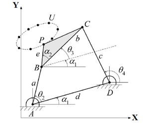
The goal is to dimensionally synthesize a 4-bar mechanism so that a tracing point on the coupler link generates a trajectory with a prescribed timing. In this regard, Nieto [6] states that in the case of mechanism synthesis, the classic optimization problem can be posed by minimizing a certain error function. Since the problem is approached as an optimization one, the design variables, objective function, and constraints must be defined.
|
| Figure 1. A four-bar mechanism that generates a trajectory |
2.1. Design variables
A set of design variables is chosen, consisting of the coordinates of the points located at the joints of the mechanism: , , , , , , , and . As shown in Figure 1, the chosen variables completely define the 4-bar mechanism and are homogeneous, making them suitable for use with genetic algorithms. However, they do not locate the tracing point in the plane, so it is chosen to coincide with one of the prescribed points. On closer analysis, it can be observed that can be expressed in terms of the other coordinates. Based on Figure 1:
|
|
(1) |
|
|
(2) |
where is the prescribed angular position of the crank corresponding to the prescribed point , which is selected to position point . Thus, the design variables are , , , , , , , and all the other variables can be calculated from these
|
|
(3) |
|
|
(4) |
|
|
(5) |
|
|
(6) |
|
|
(7) |
|
|
(8) |
where and represent the coordinates of the prescribed point . The orientation angle of the coupler link is obtained from the Freudenstein equation [6], which produces two possible values of for each of the points of interest, corresponding to the open and crossed configurations of the mechanism according to Norton [3]
|
|
(9) |
|
|
(10) |
|
|
(11) |
|
|
(12) |
|
|
(13) |
|
|
(14) |
|
|
(15) |
2.2. Objective function
The error function to be minimized is the sum of the squared distances between the prescribed points and the points where the tracer point of the mechanism actually passes through
|
|
(16) |
where , represent the coordinates of the prescribed point , and , represent the coordinates of point calculated from the angle of prescribed point . These coordinates can be calculated from the following equations:
|
|
(17) | |
|
|
(18) |
Genetic algorithms are defined to maximize a function, not to minimize it. Therefore, the problem is reformulated as a maximization problem using Eq. (19) [7,8]
|
|
(19) |
It is observed that the objective function takes values between 0 and 1, and the closer it is to 1, the better the design obtained.
2.3. Design constraints
According to Nieto [6], a design can be absurd due to having in the vector of design variables some component without physical meaning, for example, a negative length for a bar. That is why certain constraints must be imposed to delimit the design space so that it has physical meaning. Next, the constraints that each design point must satisfy are established: Grashof's condition. This establishes that the sum of the shortest () and longest () link of a planar four-bar linkage cannot be greater than the sum of the lengths of the remaining two links ( and ), in order to have a continuous relative rotation between two links, that is, at least one of the links should perform complete revolutions [3]. Grashof's law is expressed by Eq. (20)
|
|
(20) |
The Impulsor condition. SIDIGETRA should be able to obtain a crank-rocker mechanism or a double crank mechanism as chosen by the user. On one hand, if the user wants to obtain a crank-rocker mechanism (Figure 1(a)), the program restricts the crank to be the shortest link of the mechanism. To achieve this form, an adjacent link to the shortest link is fixed, and the output link behaves as an oscillator
|
|
(21) |
where is the length of the crank, is the length of the coupler, is the length of the output link, and is the length of the ground link. On the other hand, if the user wants to obtain a double crank mechanism (Figure 1(b)), the program restricts the ground link to be the shortest link in the mechanism. Both pivoted links can perform full revolutions, and the shorter crank will act as a driver.
|
|
(22) |
| ||||
| Figure 2. Inversions of the four-bar linkage mechanism. (a) Crank-Rocker. (b) Double Crank |
Coupler link angle (). Mathematically, it is known that the subradical quantity of square roots must be greater than or equal to zero, in order to avoid the result of the root being an imaginary number. Therefore, it is necessary to restrict the subradical quantity of Eq. (9) with which is calculated to be positive. In order to speed up the convergence of the genetic algorithm, only the open configuration of the mechanism is considered, so is restricted to be greater than zero.
2.4. Flowchart
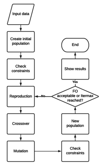
The flowchart of the program is shown in Figure 3. The flow diagram of the SIDIGETRA program starts with the input of data such as the prescribed trajectory points and the design parameters. Then, it proceeds to calculate the linkage lengths, the minimum and maximum values of the angle, and the Grashof condition check. After that, the program initializes the population of the genetic algorithm, which generates the initial designs. The designs undergo evaluation through the fitness function, and the program proceeds to the selection, crossover, and mutation stages of the genetic algorithm.
|
| Figure 3. Flowchart |
The new population undergoes the same evaluation, selection, crossover, and mutation stages until the termination criteria are met. Once the termination criteria are satisfied, the program outputs the best design along with its performance and a plot of the trajectory.
2.5. Input data
To implement the Genetic Algorithms in the SIDIGETRA program, the user must input the following data of the prescribed trajectory and design parameters:
Coordenadas de los puntos prescritos: These are the coordinates of the points on the desired trajectory to be generated (the points must be coplanar). It is a set of values in and , in addition to the corresponding rotation angles (in degrees) of the driving crank.
Maximum and minimum coordinates ( and ): These are the maximum and minimum values assigned by the user to the design variables (, , ,, , , and ) according to the physical space available for implementing the mechanism.
Four-bar linkage inversion: the user can select between crank-rocker and double-crank inversion.
Population: refers to the size of the design set, which should not be too small as it makes the execution of genetic operators difficult, and not too large as it significantly increases the program execution time for each iteration. It is recommended to use a value between 100 and 1000.
Crossover probability (Pc): determines how many times the crossover operator is executed. It should be a value between 0 and 1. A value close to 0 indicates that few crossovers will be executed, while a value close to 1 indicates that many crossovers will be executed.
Mutation probability (Pm): represents the number of times the mutation operator is executed. It should be a value between 0 and 1. A value close to 0 indicates that few mutations will be executed, while a value close to 1 indicates that many mutations will be executed.
Acceptable objective function value: this is the minimum value that the objective function needs to have for the algorithm to consider that it has found the solution. The closer the value of the objective function is to 1, the better the solution found, but at the same time, it increases the program execution time. Therefore, it is recommended to take values between 0.8 and 1.
Itermax refers to the maximum number of iterations that the Genetic Algorithm will perform.
2.6. Results
In the program interface, the user can find information about the number of iterations performed and the objective function obtained. Additionally, a graphical representation of the selected mechanism inversion is shown, along with nomenclature that allows the identification of the lengths of the links and the coordinates of the pivots and joints.
Finally, the output of SIDIGETRA is a graph that allows the comparison of the desired trajectory versus the obtained trajectory. With this graph, the user can visualize the precision with which the synthesized mechanism can generate the curve of the specified coupler point, and evaluate if it satisfies their requirements or not.
3. Validation
It is necessary to verify the functionality of the SIDIGETRA program, as well as the validity of the results obtained. To achieve this goal, the dimensional synthesis of several mechanisms is performed using SIDIGETRA, and the percent relative error between the prescribed point coordinates and the obtained point coordinates is calculated.
Then, position analyses are carried out for each synthesized mechanism using a commercial computer program, to visually compare the generated trajectories. For validation, in all cases, the exercises solved by Peón et al. [9] in their article on dimensional synthesis are taken as a reference, which are described below.
3.1. Benchmark 1
It is required to generate a trajectory with 18 prescribed points, as stated in Table 1.
| I | Desired point (X,Y) | I | Desired point (X,Y) | ||
|---|---|---|---|---|---|
| 1 | 30 | (0.5,1.1) | 10 | 210 | (0.03,0.3) |
| 2 | 50 | (0.4,1.1) | 11 | 230 | (0.1,0.25) |
| 3 | 70 | (0.3,1.1) | 12 | 250 | (0.15,0.2) |
| 4 | 90 | (0.2,1) | 13 | 270 | (0.2,0.3) |
| 5 | 110 | (0.1,0.9) | 14 | 290 | (0.3,0.4) |
| 6 | 130 | (0.05,0.75) | 15 | 310 | (0.4,0.5) |
| 7 | 150 | (0.02,0.6) | 16 | 330 | (0.5,0.7) |
| 8 | 170 | (0,0.5) | 17 | 350 | (0.6,0.9) |
| 9 | 190 | (0,0.4) | 18 | 370 | (0.6,1) |
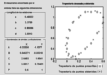
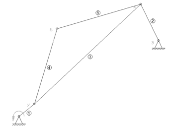
The SIDIGETRA program was used to dimension a crank-rocker mechanism with Itermax, acceptable FO, Population, Pc, Pm=, and maximum and minimum coordinate values set to 4 and -4, respectively. The program performed 5000 iterations and found an value of . Figure 4(a) shows the results obtained by SIDIGETRA, and Figure 4(b) shows the visualization of the synthesized mechanism with a simulation performed using a commercial computer tool that allows for graphical comparison of trajectories.
| ||||
| Figure 4. Crank-rocker mechanism for Benchmark 1. (a) SIDIGETRA results. (b) Simulation with dimensions in a computer tool |
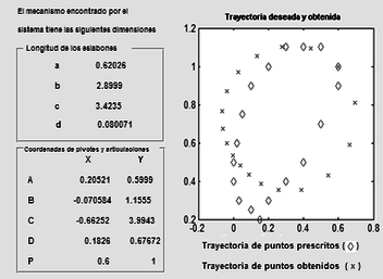
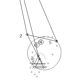
An average percentage relative error of 22.20% is obtained for the X coordinates obtained compared to the prescribed X coordinates. Regarding the Y coordinates, an average percentage relative error of 6.60% is obtained. Next, it is desired to know if it is possible to generate the same trajectory using a double-crank mechanism. The same design parameters as in the previous case are used, and the number of iterations performed by SIDIGETRA is 5000, finding an FO value of 0.74053. Figure 5 shows that the generated trajectory is approximately circular and actually not very close to the desired trajectory. It is also observed that points and are very close to each other, and therefore the length of the coupler (the value of "") is very close to zero, which is technically unfeasible for construction.
| ||||
| Figure 5. Double crank mechanism of Benchmark 1. (a) SIDIGETRA results. (b) Simulation with dimensions in a computer tool |
The average percent relative errors obtained are: erx%=70.6% and ery%=20.8%, which are much higher than those found with the crank-rocker mechanism, leading to discarding the double crank inversion for this prescribed trajectory.
3.2. Benchmark 2
We need to generate a straight line trajectory with 9 points, which are listed in Table 2.
| I | Desired point (X,Y) | I | Desired point (X,Y) | ||
|---|---|---|---|---|---|
| 1 | 90 | (8,10) | 6 | 202.5 | (3,7.5) |
| 2 | 112.5 | (7,9.5) | 7 | 225 | (2,7) |
| 3 | 135 | (6,9) | 8 | 247.5 | (1,6.5) |
| 4 | 157.5 | (5,8.5) | 9 | 270 | (0,6) |
| 5 | 180 | (4,8) |
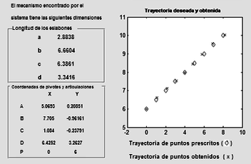
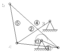
SIDIGETRA was used to find a crank-rocker mechanism. The design parameters used were: >Itermax, acceptable FO, Population, Pc, Pm, Maximum coordinate, Minimum coordinate. Results obtained: Iterations performed, FO. It is observed that the prescribed points and the obtained points are visibly close to each other (Figure 6). The mechanism found by SIDIGETRA generates the desired trajectory with a 4.11% average percentage relative error in the X-coordinates and a 0.70% average percentage relative error in the Y-coordinates.
| ||||
| Figure 6. Crank-rocker mechanism of Exercise 2. (a) SIDIGETRA results. (b) Simulation with dimensions in a computer tool |
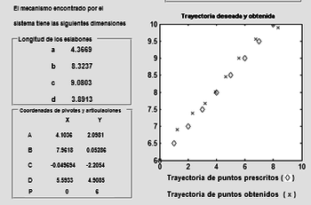
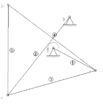
Now, we want to know if it is possible to generate the same trajectory using a double crank mechanism using the same design parameters. Figure 7 shows the results obtained by SIDIGETRA and a commercial mechanism analysis program, and it can be observed that the generated trajectory is satisfactorily close to the desired trajectory. Iterations performed, FO.
| ||||
| Figure 7. Double crank mechanism for Exercise 2. (a) SIDIGETRA results. (b) Simulation with dimensions in a computer tool |
The average percentage relative error for the coordinates is 8.8% and for the coordinates is 1.8%, which shows that SIDIGETRA found the desired trajectory. However, by comparing the FO values, the user can have a selection criterion between the inversions according to the precision requirements to solve a need.
4. Conclusions
A methodology based on the Genetic Algorithm technique was implemented to develop a computer program called SIDIGETRA, which allows for the dimensional synthesis of a four-bar linkage mechanism capable of generating a trajectory with a prescribed timing. To achieve the objective of generating a desired trajectory, the objective function to be minimized was defined as the Euclidean norm between the prescribed points and the obtained points, subject to the four-bar linkage mechanism fulfilling three constraints: 1) the Grashof condition, ensuring that at least one link is capable of completing full revolutions; 2) the coupler condition, which is related to the length of the fixed link, allowing for the evaluation of two behaviors, either the crank-rocker mechanism inversion (fixing an adjacent link to the shortest one) or the double crank mechanism inversion (fixing the shortest link); and furthermore, 3) the program was restricted to only work with the open configuration of the mechanism for both inversions, by determining the angle of the coupler link in each position.
The Genetic Algorithm method was selected to solve the optimization problem, and because this numerical technique is defined to maximize a function and not to minimize it, the minimization problem was reformulated as a maximization problem by rewriting the objective function.
The developed program offers a user-friendly interface that allows for entering the coordinates of the points of the desired trajectory to be generated together with the rotation degrees of the driving crank associated; selecting between the crank-rocker inversion or the double crank inversion; indicating design parameters that drive the application of the Genetic Algorithm, such as population size, crossover and mutation operators (Probcruce and Probmut, respectively); furthermore, the user can manipulate the execution time through the definition of an acceptable objective function or the maximum number of iterations.
As results, SIDIGETRA in each execution shows a representation of the selected mechanism inversion and its corresponding nomenclature; it calculates the dimensions of the links, specifying the coordinates of the pivots and joints. Finally, it offers a graphical comparison between the prescribed points trajectory and the obtained trajectory.
To verify the functionality of the program, several simple test examples were run consisting of dimensional synthesis of trajectory-generating mechanisms. Furthermore, the process of position analysis of each of the mechanisms was carried out using a commercial program, which allowed for visually validating the results obtained by graphically superimposing the prescribed trajectory with the trajectory generated by the synthesized mechanisms. On the other hand, the relative percentage errors between the obtained points coordinates and the prescribed points coordinates were calculated, and average values as low as 0.70% were found, demonstrating the validity of the results, and others as high as 70.6%, acceptable for numerical reasons, when the prescribed points coordinates are located close to zero.
References
[1] Erdman A.G., Sandor G.N. Diseño de mecanismos. Análisis y síntesis. Prentice Hall Hispanoamericana S.A. Naucalpán, Juarez, México, 3rd edition, 1998.
[2] Mabie H.H., Reinholtz Ch.F. Mechanisms and dynamics of machinery. Limusa, S.A. D.F., México, 2nd edition, 2007.
[3] Norton R. Design of machinery. Synthesis and analysis of machines and mechanisms. McGraw – Hill. D.F., México, 3rd edition, 2005.
[4] Rodríguez J. Nociones fundamentales para la síntesis estructural de mecanismos planos. Facultad de Ingeniería, Universidad del Zulia, Maracaibo, Venezuela, 2011.
[5] Shigley J.E., Uicker J.J. Theory of machines and mechanisms. McGraw – Hill, Naucalpán de Juarez, México, 1988.
[6] Nieto N.J. Síntesis de mecanismos. Editorial AC. Madrid, España, pp. 203, 1978.
[7] Rao S. Engineering optimization. Theory and practice. Wiley, United states, 4th edition, 2009.
[8] Gen M., Chen R. Genetic algorithms and engineering optimization. Wiley, pp. 512, 2000.
[9] Peón Escalante R., Méndez Gamboa J., Villanueva López C., Pech Oy D. Síntesis dimensional óptima de un mecanismo planar RRRR usando algoritmos genéticos. Ingeniería, Revista Académica de la FI-UADY, 13(3):5-16, 2009.Document information
Published on 31/05/23
Accepted on 22/05/23
Submitted on 13/04/23
Volume 39, Issue 2, 2023
DOI: 10.23967/j.rimni.2023.05.006
Licence: CC BY-NC-SA license
Share this document
Keywords
claim authorship
Are you one of the authors of this document?


