Published in Computational Particle Mechanics Vol. 5 (3), pp. 355-373, 2018
doi: 10.1007/s40571-017-0174-3
Abstract
In this paper we analyze the capabilities of two numerical techniques based on DEM and FEM-DEM approaches for the simulation of fracture in shale rock caused by a pulse of pressure. We have studied the evolution of fracture in several fracture scenarios related to the initial stress state in the soil or the pressure pulse peak. Fracture length and type of failure have been taken as reference for validating the models. The results obtained show a good approximation to FEM results from the literature.
Keywords: discrete element method, finite element method, FEM-DEM, pulse fracture, shale rock.
1 Introduction
Fracking techniques have become increasingly popular for the exploitation of natural gas reservoirs in shale rock. The potential of these techniques is based in the efficiency of the cracking network created in the rock. The network depends on the material properties, the fracking technology employed and the pressure function applied. The most common fracking techniques involve explosives, gas or hydraulic pressure. The initial stress state, the pressure peack and the time of application of the pressure load are relevant variables that influence the final configuration of the cracks. A brittle failure is expected to reach a wide, complex and well-connected network.
The numerical simulation of fracture is a popular research area in computational mechanics. Several numerical approaches are based on the finite element method (FEM). Non-conventional FEM technique have been formulated to properly reproduce cracks in concrete and geomaterials [1,2,3,7,10,15,16].
The discrete element method (DEM) is an alternative and efficient numerical technique to reproduce multifracture situations in a solid. The simulation of the cracking response of concrete and geomaterials have been extensively treated in the last years using the DEM [5,8,9,13,14,17,18,20,23,24,26,27], or a combination of DEM and FEM procedures [11,18,19,24,25,28].
The objective of this work is to analyze the capabilities of the DEM procedure proposed by Oñate et al. [17] and the FEM-DEM approach proposed by Zarate and Oñate [19] to simulate the fracture behavior of a shale rock when a pulse of pressure is applied. In the DEM procedure the rock is modelled as a collection of circular particles (in 2D) or spheres (in 3D). In the FEM-DEM approach the shale rock domain is initially discretized with a finite element mesh which is progressively transformed into a collection of particles as cracking evolves. Emphasis is put in the simulation of the fracture pattern, the length of the cracks and the type of failure, as these are relevant parameters for shale gas prospection in order to optimize the shape and extend of the cracking network.
Reza et al. [21,22] have presented a rate dependent constitutive model to simulated the cracks in shale rock for different pulse loads using the FEM. The results of this work are taken as a reference in this paper for comparing the cracking patterns and the types of failure for different initial stress states and pressure peaks using the DEM and the FEM-DEM techniques.
The layout of the paper is as follows. In section 2 the basic concept of pulse fracturing is presented. Section 3 presents the kinematic and constitutive equations for the DEM. Next a 2D model for the shale rock region including the geometry, the mesh, the material properties, the loading and the boundary conditions is described. Then the results for the pulse fracture problem obtained with the DEM are presented. In the following section the formulation of the FEM-DEM technique and the results obtained with this method for the same pulse fracture problem are presented. Finally, some conclusions are outlined.
2 Pulse fracturing problem
The efficiency of fracking methods demands an extensive and stable fracture network to reach the smallest gas reservoir and to extract the gas from the shale formation.
The fracture network typically depends on the geotechnical properties of the soil, the in-situ stresses when fracture is produced, the texture and the natural fracture features of the rock and the available technology to apply the fracturing load usually located within the soil at different depths. There are some different techniques to fracture the soil depending on its properties.
Hydraulic fracture is applied using gas or water at high pressure under a relatively slow loading rate loading producing a one-wing or at the most bi-wing fracture scheme [21] aligned with the direction of the maximum main stress, which reduces the expansion area of the crack.
Explosives imply a very high rate of loading leading to the simultaneous propagation of multiple fractures. Due to the high stresses and heat flux, the material next to the blasting point reaches a plastic behavior. Hence, a compaction pattern with residual stresses in the soil remains after the explosion.
Pulse fracturing considers a peak load slightly exceeding the maximum and minimum in-situ stresses but lower than the plastic or compaction limit. Peak loads and loading rates can be customized according to the soil mechanical properties to reach an optimized cracking network to improve the shale gas production efficiency. Brittle fractures are optimum for that goal so the definition of the pressure pulse is compulsory.
Typically the pulse fracturing process involves two loading processes. First, the combustion of the propellant leads to a dynamic load characterized by high energy stresses and shock waves next to the wellbore. High amplitude compressive stresses waves propagate around the wellbore and within the rock mass. As consequence, the surrounding rock support tensile stresses. The result are radial cracks with different orientations.
Once the first radial cracks appear, gas penetrates into them increasing the width and depth of the existing cracks. This second phase is developed at a lower speed as a quasi-static process [22]. The gas penetration can create cracks of significant length.
In our work the DEM and DEM-FEM techniques proposed in [17] and [19], respectively are used for modelling the initial radial cracks induced by the pressure pulse. The effect of gas penetration on the cracks is not taken into account in our work. Hence, the actual fracture pattern will exhibit extended fractures for all the cases studied. Gas penetration into the fracture network can be considered using the computational strategy presented in [28].
3 DEM numerical simulation
3.1 DEM model overview
The DEM was initially developed by Cundall et al. [4] in the 1970's. It is based in the interaction of discrete elements (also called particles) – typically cylinders (in 2D) and spheres (in 3D) – to simulate the behavior of continuum and discontinuum domains. This interaction is governed by a set of kinematic equations involving the forces acting over the discrete elements and the displacements, velocities and accelerations of the elements. The forces acting over a discrete element are related to the stresses and strains according to a particular constitutive model. In our work we use the local constitutive model for the DEM for cohesive and non-cohesive materials proposed by Oñate et al. [17]. In the following a brief description of this model is presented.
3.1.1 Kinematic equations and integration scheme
The translation and rotation of the discrete particles is governed by the standard dynamics equations for rigid bodies,
|
|
(1) |
where and are the -th particle displacement and the angular velocity, and are mass and the inertia of the particle, and and are vector containing the forces and torques resultant respect to the central axes due to the interaction of a particle with its neighbors (Figure 1).

|
| Figure 1: Motion of a rigid particle |
The set of forces applied on a particle include external forces (), damping forces () and interaction forces between neighbor particles () (Figure 2)
|
|
(2) |
where is the number of particles that are in contact with the th particle.

|

|
| (a) | (b) |
| Figure 2: (a) Definition of contact interfaces. (b) Forces acting on a contact interface section along the normal and shear directions | |
The expression for the torques can be derived from Eq.2 [18]. The dynamic equations (??) are integrated in time using an explicit scheme as shown in Eq.3 for the translation motion
|
|
(3) |
The explicit time integration scheme is chosen due to the high computational cost of the DEM solution for large problems. However the stability of the scheme is conditioned to the time step value. The critical time step is related to the high frequency of the problem, (), i.e.
|
|
(4) |
where is a fraction of the critical damping [ ].
3.1.2 Forces acting over the discrete element
The interaction forces at the contact interface between two particles and () are obtained from the normal () and tangential () components (Figure 2b).
The normal component of the interaction forces is calculated as,
|
|
(5) |
where is the normal stress at the contact interface, is the minimum radius between the two particles (Figure 2a) and is a parameter that depends on the number of contacts and the packing of the particles [17]. In our work we have used a global definition of . where and are the average number of contacts per sphere and the average porosity for the whole particle assembly. The normal stress is calculated from the strain and the strain rate along the normal direction as,
|
|
(6) |
where is the Young modulus, is a local damping parameter calculated as a fraction of the critical damping per unit of length, as
|
|
(7) |
where is the normal stiffness parameter (see Eq.9).
The normal strain and strain rate values are computed from the kinematic variables as,
|
|
(8) |
where and are the relative displacement and the relative velocity between two particles along the normal direction at the contact interface and is the distance between the centroids of the two particles (Figure 2a).
Equations 5–8 lead to a general relation between the normal force and the kinematic variables (Figure 2b) as
|
|
(9) |
where and are the normal stiffness and the normal viscous damping parameters that can be deduced from Eq.9.
A similar approach leads to the constitutive expression for the shear forces in the two tangential directions as (Figure 2b) [17]
|
|
(10) |
where vector contains the shear components of the relative displacements between particles. This vector is calculated as,
|
|
(11) |
Equation 10 leads to a general expression for the shear stiffness (assumed to be the same for both shear directions), as
|
|
(12) |
where is the Poisson's ratio of the material.
The damping forces are computed from the application of a global damping over the set of particles. This damping component is characterized by translation () and rotation () damping parameters defined as a fraction of the stiffness parameters. In this work we have taken . The damping forces act in opposite direction to the motion of the particles according to the following expressions [17]:
|
More details of the local constitutive model for the DEM can be found in [17].
3.2 Normal and shear failure
Cohesive bonds at a contact interface are assumed to start breaking when the interface strength is exceeded in the normal direction by the tensile contact force, or in the tangential direction by the shear force. The uncoupled failure (decohesion) criterion for the normal and tangential directions at the contact interface between particles and is written as
|
|
(14) |
where and are the interface strengths for pure tension and shear-compression conditions, respectively, is the normal tensile force and is the modulus of the shear force vector defined in Eq.(10).
The interface strengths are defined as
|
|
(15) |
where and are the tensile and shear strengths respectively, is the compressive normal force at the contact interface and is a (static) friction parameter, where is an internal friction angle. These values are assumed to be an intrinsic property of the material and are determined experimentally. In our work is taken as the tensile strength of the material measured in a bending-tensile (BT) test (i.e. ).
As for the shear strength we have estimated its value as a percentage of the maximum compressive stress in an UCS test, , as
|
|
(16) |
where is a parameter that is calibrated in numerical experiments via UCS and BTS tests. For shale rock materials we have used .
Following tension failure, the constitutive behavior in the shear direction is governed by the standard Coulomb law
|
|
(17) |
where is a dynamic Coulomb friction coefficient and is the post-failure internal friction angle. The value of is determined from experimental tests.
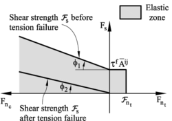
Figure 3a shows the graphical representation of the failure criterium described by Eqs.(14), (15) and (17). This criterium assumes that the tension and shear forces contribute to the failure of the contact interface in a decoupled manner. On the other hand, shear failure under normal compressive forces follows a failure line that is a function of the shear failure stress, the compression force and the internal friction angle.
Elastic damage under tensile and shear conditions has been taken into account in this work by assuming a linear softening behaviour defined by the softening moduli and introduced into the force-displacement relationships in the normal (tensile) and shear directions, respectively. Figure 4 shows the evolution of the normal tension force and the shear force at a contact interface until failure in terms of the relative normal and tangential displacements. The effect of damage in the two constitutive laws is also shown. For details see [17].
|
| Figure 3: Failure line in terms of normal and shear forces. Uncoupled failure model |

|
| Figure 4: Undamaged and damaged elastic moduli under tension (a) and shear (b) forces |
3.3 Elasto-plastic model for compression forces
The compressive stress-strain behaviour in the normal direction at the contact interface for frictional cohesive materials, such as cement, rock and concrete, is typically governed by an initial elastic law followed by a non-linear constitutive equation that varies for each material. The compressive normal stress increases under linear elastic conditions until it reaches the limit normal compressive stress (also called yield stress). This is defined as the axial stress level where the experimental curve relating the axial stress and the axial strain starts to deviate from the linear elastic behaviour. After this point the material is assumed to yield under elastic-plastic conditions.
The elasto-plastic relationships in the normal compressive direction are defined as
Loading path
|
|
(18.a) |
Unloading path
|
|
(18.b) |
In Eqs.(18) and are respectively the increment of the normal compressive force and the normal (relative) displacement, is the initial (elastic) compressive stiffness for a value of (Figure 5), and is the tangent compressive stiffness given by
|
|
(19) |
where is the slope of the normal stress-strain curve in the elastoplastic branch (i.e. , , in Figure 5).
Plasticity effects in the normal compressive direction also affect the evolution of the tangential forces at the interface, as the interface shear strength is related to the normal compression force by Eq.(15).
Figure 5 shows the diagram relating the compressive axial stress and the compressive axial strain used for modelling the elasto-plastic constitutive behaviour of shale rock at the contact interfaces. The form of each diagram is obtained from experimental tests on cylindrical samples.

|
| Figure 5: Compressive axial stress-compressive axial strain diagram for elastoplastic material. LCS1 : limit compressive stress defining the onset of elastoplastic behaviour at the contact interface |
3.4 Calibration of the material parameters
Oñate et al. [17] have proposed a methodology to calibrate the material parameters for shale rock for the local DEM model presented in the previous section, using experimental results from material tests. Table 1 summarizes the DEM constitutive paramaters for the analysis of shale rock in this work. For more details see [17].
| (g/cc) | (GPa) | (MPa) | (MPa) | |||
| 2.55 | 0.7 | 0.6 | 30 | 0.2 | 5.0 | 25 |
| LCS1 | LCS2 | LCS3 | YRC1 | YRC2 | YRC3 | |
| (MPa) | (MPa) | (MPa) | ||||
| 20 | 30 | 40 | 2 | 5 | 10 | 1.0 |
The DEM formulation and the constitutive model presented in the previous lines have been implemented in the DEMPack code (www.cimne.com/dempack). The geometry, the discretization mesh and the postprocessing of the results have been performed with the pre-postprocessor GiD [6]. Both software codes have been developed at CIMNE.
3.5 UCS and BTS tests on shale rock material
We have simulated with the DEM a UCS test and a BTS test on a shale rock material corresponding to a Middle Brown gaseous shale in Devonian formation from Lincoln County, West Virginia. The essential material parameters for the DEM simulations were taken from [21].
The simulations were carried out in a cylindrical sample of dimensions mm. The material properties used for the DEM analysis are listed in Table 1. The value of MPa was obtained using Eq.(16) with and MPa as reported in [21].
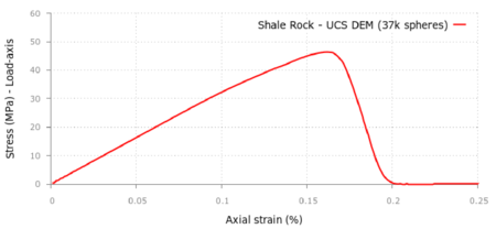
The curve in Figure 6 shows the axial stress-axial strain curve for the UCS test. A maximum compressive stress of 48 MPa was obtained using a discretization of 37000 spheres. This yields a 4% error versus the experimental value of 50 MPa [21].
|
| Figure 6: Axial stress-axial strain curve for UCS test in shale rock material. DEM results using 37000 spheres |
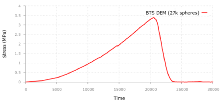
The curve in Figure 7 shows the tensile stress - versus time for the BTS test obtained with the DEM using 27000 spheres. A failure tensile stress of MPa was obtained. This gives a 8% error versus the experimental value of MPa.
|
| Figure 7: Tensile stress-time curve for BTS test in shale rock material. DEM results using 27000 spheres |
3.6 DEM simulation of pulse fracture of a shale rock mass
We present the application of the DEM technique previously described to the fracture of a shale mass under a pulse load.
3.6.1 Geometry and mesh
The reference problem [21] considers a square geometry 200 ft per side modelled assuming horizontal and vertical symmetry. The geometry in the simulation is a 100 ft (30,48m) sided square, with the wellbore in the lower left corner.
In this work the pulse fracture problem has been simulated using a two-dimensional (2D) plain strain square geometry of 15x8 m, assuming horizontal symmetry.
The analysis domain has been discretized with the DEM using 882693 circular discrete elements of 25 mm radius (average).
A wellbore with 152,4 mm diameter (6 inch) has been introduced in the center of the lower part of the square domain where the pulse load is applied.
The boundary conditions applied consider that no displacement is observed far away enough from the wellbore. Hence, prescribed zero displacements are applied at every boundary.
The point of application of the pulse is located deep into the ground where a pre-existing stress state exists, depending on the depth. This stress state becomes an initial stress field for the pulse fracturing problem and is a relevant variable in this study to analyze the different cracking patterns. The simulation is then split into two phases:
- A velocity is applied at the boundaries in order to reproduce the initial stress state. The velocity is approximated so that the stress distribution reaches the expected value and shows a high degree of uniformity. The duration of this first pulse is 100 ms in order to ensure the stability of the results. This first phase takes most of the calculation time due to the dynamic response of the problem.
- Once the initial stress state is reached, zero displacements are prescribed at all boundaries and then, the pulse load is applied. The calculation time includes a time interval after the pulse to reach the stationary state after the pulse.
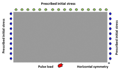
The analysis domain is shown in Figure 8 with the location of the wellbore, the symmetry axis and representation of the initial stress field prescribed at the boundaries.
|
| Figure 8: Numerical model. Geometry and applied loads |
3.6.2 Pressure pulse application
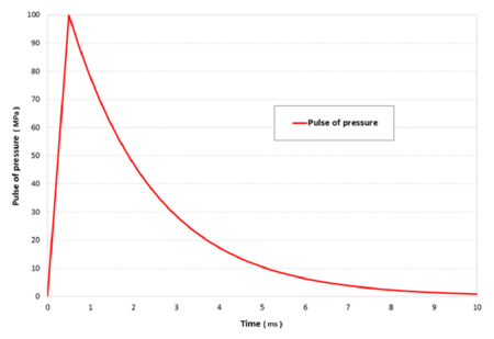
The pulse loading curve is characterized by a linear rising branch up to the peak load, and an exponential decay (Figure 9). The expression for the pulse load is
|
|
(20) |
where is the rising loading rate, is the maximum loading pressure and is the time for the maximum value of the loading pressure (). The decay exponent is taken as constant and equal to .
Two pulse loading curves have been considered. The reference pulse loading has a peak of 100 MPa at a time of 0.50 ms; this means a loading rate () of 200 MPa/ms. This reference pulse is applied for different initial stress states of the soil corresponding to different depths.
|
| Figure 9: Loading pulse pressure function |
To study the capabilities of the model, a variation of the pulse load is considered by increasing the pressure peak to 250 MPa, keeping the same loading rate. The load curve parameters are shown in Table 2.
| Pulse | Peak (MPa) | Loading rate (MPa/ms) | Peak time (ms)
|
| Reference | 100 | 200 | 0.50 |
| Peak 250 | 250 | 200 | 1.25
|
The pressure load is modeled by applying a point load over the particles located in the wellbore bound. This load is calculated taking into account the pressure value and the area of the particles affected by the load. The force is applied to each particle in the radial direction with respect to the wellbore center.
3.6.3 Initial stress state
Three different samples of shale rock at different depths are considered. The depth of these samples determines the initial stress state when the pressure pulse takes place.
Taking into account the horizontal stress and the pore pressure gradient considered in [21] the initial horizontal stresses are calculated and details are given in Table 3. The initial stresses are assumed to be constant over the analysis domain. Three different depths have been considered leading to the same number of simulation cases. An additional case is considered for a sample extracted from the surface, i. e. with zero initial stress. This case shows the top value of the cracks and is taken as a reference.
The study includes the influence of the anisotropy in the cracking response of the shale material, because of its importance in the fracture pattern according to [21].
For all the cases mentioned before, a reference pulse loading is applied, with a load peak of 100 MPa at a loading rate of 200 MPa/ms.
| Depth (ft) | (MPa) | (MPa)
|
| 0 | - | - |
| 500 | 1.0 | 1.2 |
| 5 000 | 10.0 | 12.0 |
| 10 000 | 20.0 | 24.0
|
3.7 DEM results
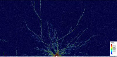
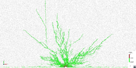
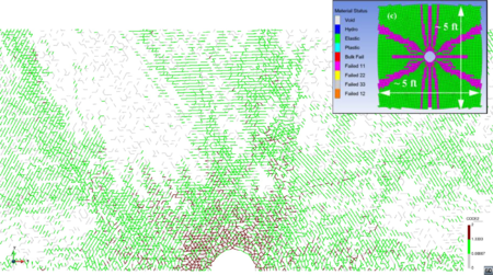
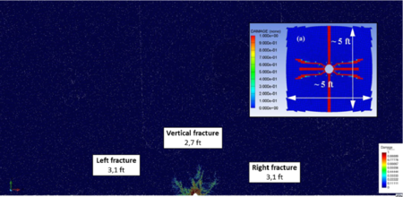
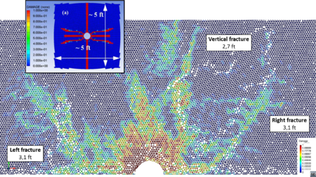
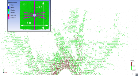
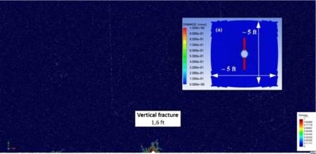
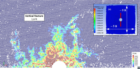
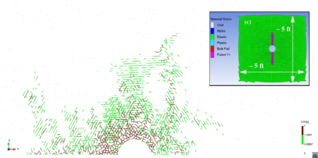
In this section simulation results for the pulse fracturing problem using the DEM formulation described earlier are presented. Fracture simulation results respect to depth of the sample, that is, the initial stress state in the soil when the pulse is applied, are presented in Figures 10 to 13. They show the fracture pattern and the type of fracture with the numerical results taken as reference, which are depicted in the same figures.
The fracture pattern is represented as a damage distribution around the wellbore after the pulse loading has been applied. The damage parameter takes into account the number of broken bonds over the initial number for every single element, and so, it varies from zero to one for every particle.
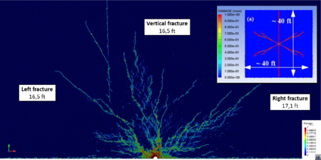
The fracture length is measured as the line distance between the farther damaged points from the wellbore for a defined fracture. Due to the symmetry of the numerical simulation, the lengths depicted in the figures are half of the DEM results. The fracture length computed with the DEM is given in Table 4 and compared to the FEM results presented in [21]. DEM and FEM results agree reasonably well for the cases considered.
| Depth | Pressure peak | Fracture length (ft) | Fracture length (ft) | Figure | ||
| (ft) | (MPa) | (MPa) | (MPa) | FEM result [21] | DEM result |
|
| 0 | 0 | 0 | 100 | – | 40 | 10 |
| 500 | 1.0 | 1.2 | 100 | 40 | 33 | 11 |
| 5000 | 10 | 12 | 100 | 5 | 5.4 | 12 |
| 10000 | 20 | 24 | 100 | 2.3 | 3.2 | 13 |
| 5000 (weak anisotropy) | 5 | 12 | 100 | – | 10.5 | 14a |
| 5000 (strong anisotropy) | 2.5 | 12 | 100 | – | 15,2 | 14b |
| 5000 | 10 | 12 | 250 | 28 | 30.2 | 15
|
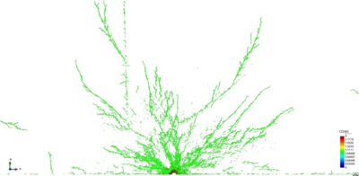
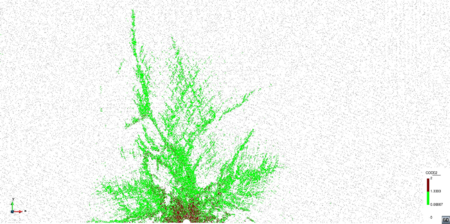
The type of fracture is represented in the figures for every single case to highlight the difference between tensile (green) and shear (red) failure, due to the importance of this result. Reference results [21] are depicted over the DEM simulations, so as to ease the comparison.
3.7.1 Fracture vs initial stress state
The fracture length in the DEM simulation shows a branching distribution similar to the reference results [21] although the fracture is not so clearly defined because of the DEM discretization. The fracture lengths are comparable as well as the type of failure, mainly due to tensile failure in both cases.
The results with zero initial stress state – depth of 0ft (Figure 10) show a similar fracture distribution and pattern to the results for 500 ft (Figure 11).
|
| (a) |
|
| (b) |
| Figure 10: Damage distribution (a) and type of fracture (b). No initial stress. Peak pressure load: 100 MPa |
| |
| (a) | |
|
|
| (b) | (c) |
| Figure 11: Damage distribution (a) and type of fracture (b and c). Depth 500 ft. MPa, MPa. Peak pressure load: 100 MPa. FEM results in box from [21] | |
The fractured area decreases as the initial stresses increase their value (Figures 11––13). The fracture length is comparable to the reference results [21]. Side fractures appear although they are not so well defined so as to be compared with the reference results.
| |
| (a) | |
|
|
| (b) | (c) |
| Figure 12: Damage distribution (a) and (b) and type of fracture (c). Depth 5000 ft. MPa, MPa. Peak pressure load: 100 MPa. FEM results in box from [21] | |
The type of fracture is mainly due to tensile forces in both cases, although in the DEM simulation a small fracture area due to shear effects appears.
| |
| (a) | |
|
|
| (b) | (c) |
| Figure 13: Damage distribution (a) and (b) and type of fracture (c). Depth 10000 ft. MPa, MPa. Peak pressure load: 100 MPa. FEM results in box from [21] | |
The high initial stress level leads to a small fracture in the DEM simulation. Length values are comparable to those in [21], as well as the type of failure.
3.7.2 Fracture vs anisotropy
A further study of the cracking response has been carried out to verify the assumptions pointed out in [21] in relation to the degree of anisotropy of the initial stress field. Fractures tend to follow the direction of the maximum stress at each point and this behavior increases with the level of stress anisotropy in the soil.
Two scenarios have been studied to analyze the capability of the DEM to reproduce this phenomenon. The degree of anisotropy is introduced by decreasing the minimum horizontal stress (), while the maximum stress () remains unchanged taking as reference the sample at 5000 ft. depth and the reference pulse loading. These simulation cases are not studied in [21], so there are no reference values for these results.
Two stress fields have been considered – weak and strong anisotropy – by decreasing the minimum horizontal stress to a 50% and 25% respectively, of its reference value. The initial stresses considered in these two scenarios are shown in Table 4.
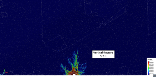
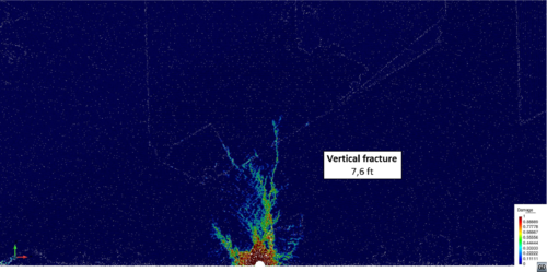
Figure 14 shows the results obtained for the damage distribution for both cases. The results show a clear trend for the fractures that follow a predominant vertical direction coincident with the maximum stress . The fracture length increases with the degree of anisotropy, as expected. The results evidences show that the DEM has a remarkable capability to reproduce the anisotropic effects in the fracture pattern for a pulse load.
|
|
| (a) Weak anisotropy MPa, MPa | (b) Strong anisotropy MPa, MPa |
| Figure 14: Damage distribution for weak (a) and strong (b) anisotropy (Table 4). Depth 5000 ft. Peak pressure load: 100 MPa | |
3.8 Fracture vs peak load
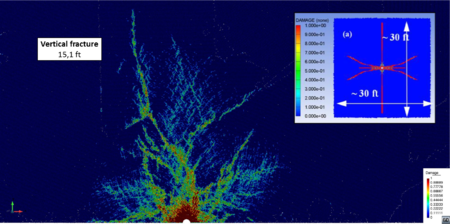
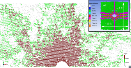
Finally, as the third significant variable, the effect of the pulse peak loading on the fracture pattern is studied, keeping the loading rate constant. Fracture patterns have been obtained for the depth of 5000 ft and two loading peaks: 100 and 250 MPa. Results are depicted in Figures 12 and 15 including the reference results [21].
The higher value of the peak pressure load the larger is the fracture zone and so is the fracture length. An increase of the shear failure area is appreciated both in the DEM results and the reference work (Figure 15). The fracture length obtained in this work is in agreement with that in [21].
| |
| (a) | |
|
|
| (b) | (c) |
| Figure 15: Damage distribution (a) and failure criteria (b). Depth 5000 ft. MPa, MPa. Peak pressure load: 250 MPa. FEM results in box from [21] | |
4 FEM-DEM numerical simulation
4.1 Constitutive model overview
The DEM is a flexible method to simulate non-continuum media, in particular the propagation of initial cracks. The contact properties between particles are a powerful degree of freedom to control the onset and propagation of cracks.
On the other hand, these contact properties are defined in the micro scale, while the material properties usually refer to experimental results in the macro scale. The step between both scales is not easy and needs a calibration task. The FEM otherwise is based in a continuum formulation involving the macro properties of the material. This feature avoids the calibration task and leads to the current stress state at any calculation point. For that reason the FEM allows one to establish failure criteria compatible with the energy balance equations, which makes it consistent and easy to apply for different materials.
The distance between DEM and FEM approaches is wide. Extensive research has been carried out in last years [11,18,24] to combine the FEM and the DEM procedures, taking profit from the advantages of both numerical methods. Zárate and Oñate [19] have recently presented a coupled FEM-DEM formulation for the numerical simulation of cracks starting from a continuum discretization of the domain. This formulation is used here for simulating the fracture of shale rock under a pulse load.
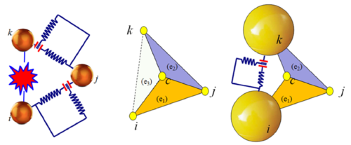
In the 2D FEM-DEM formulation considered here the continuum is initially discretized using linear 3-noded triangles whose nodes define the eventual future location of a discrete element. The DEM only takes part in the simulation process when cracks appear. The normal contact forces between discrete elements are calculated by integrating the stiffness matrix of the linear triangle along its sides. Each side connects the discrete particles as shown in Figure 16 [27]. The mechanical problem in the crack-free region is solved using the standard FEM.

|
| Figure 16: Equivalence between stiffness matrix (FEM) and cohesive link (DEM) |
A damage model has been implemented in the FEM formulation to simulate the response of the continuum domain. The onset of a crack depends on the damage level in each triangular element calculated as an internal variable (d) at each point according to a failure criteria. The stress over the edge is computed as a mean value of the stresses in the elements sharing that edge. The stress state leads to a damage level calculated using the Mohr-Coulomb failure criteria.
A smoothing technique is employed to determine the damage over the element edges. Once the damage limit is reached, a stiffness loss is assumed in the triangle element associated to the area determined by the centroid of the triangle and the damaged edge as shown in Figure 17.
|
| Figure 17: Equivalence between stiffness matrix (FEM) and cohesive link (DEM) with a damaged edge |
|
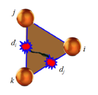
| Figure 18: 3-noded triangle with two sides damaged |
The largest damage parameter in two of the three sides of the element (Figure 18) determines the stiffness matrix of the element that is recalculated at every time step as follows,
|
|
(21) |
where is the initial stiffness matrix of the undamaged element and and are the two maximum values of the damage parameter for the three element sides.
When a cohesive bond is removed, the side nodes of the element are disconnected and two discrete particles are introduced precisely at the same nodal position. Their radius and mass are defined as the maximum ones to guarantee the contact without overlapping other discrete elements so as to avoid spurious forces from the numerical approximation. There are several algorithms to define these discrete elements in the literature [12].
Once the discrete particles are created their interaction is governed according the contact and friction laws, as in the general DEM formulation described earlier.
A relevant point in this FEM-DEM approach is its low computational cost. Most of the cost in a DEM simulation is due to the contact searching algorithms. In the FEM-DEM technique the number of discrete elements is in general much lower than the number of nodes because the fractured area is expected to be smaller than the whole calculation domain. Hence, the computational time consumed by the searching algorithms is much lower than in a standard DEM solution.
4.2 Numerical model
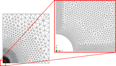
The pulse fracture problem described in Section 3.6 has been solved with the FEM-DEM technique presented above assuming a double symmetry respect to the wellbore. A 2D square domain of 8 m side length has been discretized using the finite element mesh of 22128 3-noded linear triangles and 11237 nodes as depicted in Figure 19. The size of the elements is variable from a minimum of 12 mm in the finer bound next to the wellbore to a maximum of 900 mm far from the wellbore where fracture is not expected.
|
| Figure 19: Numerical model. General view and wellbore detail |
The pressure pulse has been applied in the round bound of the wellbore by means of a distributed load with the time evolution function described in Section 3.3.2. The effect of the gas pressure within the cracks has been modeled by applying the pressure force (deduced from the values of Figure 9) at the side of the elements adjacent to the crack. The problem is assumed to be dynamic. An explicit scheme has been employed for the time integration of the discretized dynamic equations in both the FEM and DEM domains.
4.3 Material parameters
The material properties of the shale rock correspond to the constitutive parameters presented in [21]. Table 5 list the values used in the numerical simulation.
| Shale rock constitutive parameters. FEM-DEM model
| |||
| Parameter | Notation | Value | Units |
| Density | 2550 | kg/m | |
| Young modulus | E | 30 000 | MPa |
| Poison coefficient | 0.20 | [ - ] | |
| Yield strength | 5.0 | MPa | |
| Fracture energy | G | 32 | J/m
|
4.4 FEM-DEM results of pulse fracture simulation of shale rock mass
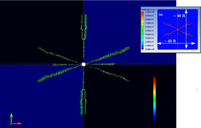
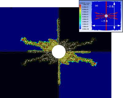
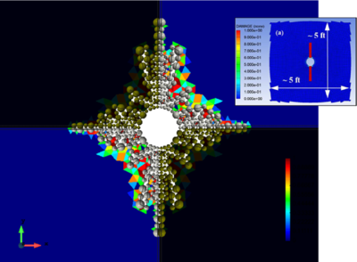
Three different cases of pulse fracturing of shale rock mass have been simulated using the FEM-DEM approach for different depths as described in Table 3 for the DEM simulation, with the corresponding initial stress states. For every case the pattern and the fracture length have been measured and compared to the reference values in [21]. Results have been treated to show the whole fracture by a symmetric extension of the results obtained in the quarter domain.
Figures 20 to 22 show the crack pattern obtained with the FEM-DEM formulation compared to the reference results [21] depicted in a box for the three cases considered.
 ] ]
|
| Figure 20: Crack simulation with FEM-DEM model. Depth 500 ft. FEM results in box from [21] |
 ] ]
|
| Figure 21: Crack simulation with FEM-DEM model. Depth 5000 ft. FEM results in box from [21] |
 ] ]
|
| Figure 22: Crack simulation with FEM-DEM model. Depth 10000 ft. FEM results in box from [21] |
The lengths of the cracks obtained with the FEM-DEM approach are shown in Table 6. Good agreement with the results reported in [21] is obtained.
| Case | FEM (ft) | DEM-FEM(ft)
|
| Depth 500 ft | 40 | 33 |
| Depth 5000 ft | 5 | 5.4 |
| Depth 10000 | 2.3 | 3.2
|
5 Concluding remarks
Two different numerical methods based on DEM and the FEM-DEM techniques have been presented and applied to the simulation of cracking in a shale rock reservoir under a pressure pulse.
The DEM is able to reproduce the multicracking pattern in the shale rock induced by the pressure pulse. The cracking pattern and its length is consistent with the reference FEM results.
A FEM-DEM technique has also been applied to the same problem. The cracks obtained with this model reproduce the crack pattern and length obtained with the FEM (and also the standard DEM) with a lower computational cost.
The results presented show the capabilities of the DEM and the FEM-DEM approaches here described to simulate the cracking behavior of shale rock and other geomaterials under a pressure pulse.
The effect of the gas pressure within the cracks can be accounted for by coupling the FEM-DEM approach with an embedded FEM solver for a compressible gas. The coupling strategy solves the equation for the gas flow in the finite element mesh that fills the spaces created by cracks. Details are given in [28]
The extension of both numerical models to 3D problems is straightforward and will be reported in future publications.
Acknowledgements
This work has been carried out with the financial support from Advanced grant projects COMDESMAT and ICEBREAKER of the European Research Council and the BALAMED project (BIA2012-39172) of MINECO (Spain). The support of CIMNE for making available the DEMPack code (www.cimne.com/dempack) and the GiD pre-postprocessor (www.gidhome.com) is gratefully acknowledged.
REFERENCES
[1] Cervera M., Chiumenti M., Codina R. (2010) Mixed stabilized finite element methods in nonlinear solid mechanics Part I: Formulation. Computer Methods in Applied Mechanics and Engineering 199:2559–2570
[2] Cervera M., Chiumenti M., Codina R. (2010) Mixed stabilized finite element methods in nonlinear solid mechanics Part II: Strain localization. Computer Methods in Applied Mechanics and Engineering 199:2571–2589
[3] Cervera M., Chiumenti M., Codina R. (2011) Mesh objective modelling of cracks using continuous linear strain and displacements interpolations. Int. J Num. Meth. Eng. 87:962–987
[4] Cundall PA, Strack ODL. (1979) A discrete numerical method for granular assemblies. Geotechnique 2:47–65.
[5] Donzé F., Richelieu F., Magnier S. (2009) Advances in discrete element method applied to soil, rock and concrete mechanics in state of the art of geotechnical engineering. Electro J Geotechnical Eng. 8:1-44.
[6] GiD The personal pre and postprocessor. Version 13.0 (2017) (www.gidhome.com).
[7] Hernandez J.A., Oliver J., Cante J.C., Weyler R. (2011) Numerical modeling of crack formation in powder forming processes. International Journal of Solids and Structures. 48(2):292–316.
[8] Hsiegh Y-M, Li H-H, Huang T-H, Jeng F-S. (2008) Interpretations on how the macroscopic mechanical behavior of sandstone affected by macroscopic properties revealed by bonded-particle model. Eng. Geol. 99(1):1-10.
[9] Huang H. (1999) Discrete element modelling of tool-rock interaction. Ph.D Thesis, University of Minnesota.
[10] Johnson P.R., Petrinic N., Süli E. (2005) Element-splitting for simulation of fracture in 3D Solid continua. VIII International Conference on Computational Plasticity, Barcelona.
[11] Katagiri S., Takada S. (2003) Development of FEM-DEM combined method for fracture analysis of a continuous media. Memoirs of the Graduate School of Science and Technology, Kobe University. 20A, 65-79. Kobe University
[12] Labra C., Oñate E. (2009) High-density sphere packing for discrete element method simulations Commun. Numer. Meth. Engng. 25(7):837–849.
[13] Labra C., Rojek J., Oñate E., Zarate F. (2008) Advances in discrete element modelling of underground excavations. Acta Geotech 3(4):317–322.
[14] Munjiza A. (2004) The combined finite-discrete element method. Wiley & Son.
[15] Oliver J., Caicedo M., Roubin E., Huespe A.E., Hernandez J.A. (2015) Continuum approach to computational multiscale modeling of propagating fracture. Comput. Meth. in Appl.Mech. and Engng, 294:384–427.
[16] Oliver J., Huespe A.E., Dias I.F. (2012) Strain localization, strong discontinuities and material fracture: Matches and mismatches Computer Methods in Applied Mechanics and Engineering. Volume 241-244, 1 October 2012, Pages 323-336
[17] Oñate E., Zarate F., Miquel J., Santasusana M., Celigueta M.A., Arrufat F., Gankikota R., Valiullin K., Ring L. (2015) A local constitutive model for the discrete element method. Application to geomaterials and concrete. Computational Particle Mechanics. 2:139–160.
[18] Oñate T., Rojek J. (2004) Combination of dicrete element and finite element methods for dynamic analysis of geomechanics problems. Comput. Methods Appl. Mech. Eng. 193:3087-3128.
[19] Zarate F., Oñate E. (2015) A simple FEM-DEM technique for fracture prediction in materials and structures Computational Particle Mechanics, 2(3):301-314.
[20] Potyondy D., Cundall P. (2004) A bonded-particle model for rock. Int J Rock Mech Min Sci 41(8):1329-1364. Rock Mechanics Results from the Underground Research Laboratory, Canada.
[21] Reza Safari M., Gandikota R., Mutlu U., Ji M., Glaville J., Abass H. (2013) Pulsed fracturing in shale reservoirs: geomechanical aspects, ductile-brittle transition and field implications. Unconventional Resources Tecnology Conference (URTeC), Denver, CO, USA, 12-14 Aug. 2013, pp. 448–461.
[22] Reza Safari M., Huang J., Mutlu U. (2013) Ductile to brittle transition, generation of complex fracture networks and engineering implications. Applied Geoscience Conference. Houston (Texas).
[23] Rojek, J., Labra C., Su O., Oñate E. (2012) Comparative study of different micromechanical parameters. Int J Solids Struc 49(13):1497-1517.
[24] Rojek J., Oñate E. (2007) Multiscale analysis using a coupled discrete/finite element model. Interact. Multiscale Mech 1(1):1-31.
[25] Santasusana M., Irazábal J., Oñate E., Carbonell J.M. (2016) The Double Hierarchy Method. A parallel 3D contact method for the interaction of spherical particles with rigid FE boundaries using the DEM. Comp. Part. Mech. 3:407–428.
[26] Tran V-T., Donzé F-V., Marin P. (2011) A discrete element model of concrete under high triaxial loading. Cem Concr Compos 33(9):936-948.
[27] Ubach P.A., Arrufat F., Ring L., Gandikota R., Zarate F., Oñate E. (2016) Application of an enhanced discrete element method to oil and gas drilling processes. Comp. Part. Mech. 3(1):29–41.
[28] Zárate F., Löhner R., Oñate E. (2017) Modeling of multifracture in solids induced by bleat load accounting for coupled gas-structure interaction effects. Comput. Particle Mechanis, (In preparation).
Document information
Published on 01/01/2018
DOI: 10.1007/s40571-017-0174-3
Licence: CC BY-NC-SA license