Abstract
The ever-increasing complexity of design processes fosters novel design computation models to be employed in architectural research and design in order to facilitate accurate data processing and refined decision making. These computation models have enabled designers to work with complex geometry and numeric design constraints to explore a whole new design field that is impossible to explore without computation techniques. However, most current design computation models follow an automation-oriented paradigm that only deal with strictly defined problem solving and optimization, but fail in establishing an intuitive and interactive communication with designers. This lack of interaction leads to an unconscious rejection of non-parameterizable design factors, which, reduces design computation models to specific design problem solving tools instead of operating as active design partners. This paper presents a non-deterministic design computation modeling approach derived from a discussion on quantum design paradigm, which employs real-time user interaction as the co-driver to evolve user+computation driven informed design outputs. A case study of such a design computation model; QPC Toolset, developed and applied in a QuantumPointCloud workshop, will be illustrated in this paper. Expanded discussions on fabrication optimization and construction techniques from the QPC workshop will be addressed to conclude a comprehensive report.
Keywords
Interactive design computation modeling ; Quantum Paradigm ; Hotwire cutting ; Point cloud ; Design constraint
1. Introduction
Architecture design is driven by a complex network of discrete decision making processes, which transform, crossbreed and mutate raw design data with subjective design intention and objective design constraints. With the rapid development of design computation techniques, complex computation models have been employed to facilitate sophisticated design decision-making and data management (Menges and Ahlquist, 2011 ). These computation models have enabled designers to work with highly complex geometry and huge amount of data to explore a whole new design field that is hardly achievable without computation techniques (Oosterhuis, 2011 ). However, followed an automation oriented design paradigm, most of current design computation models are constructed as efficient design problem solvers that clearly distinguish themselves from the rest of design decision making network. The communication with these isolated computation models heavily relying on numeric data thus fail in establishing an intuitive and efficient communication with designers, as not all subjective design intentions can be converted to parametric rules and coined into design computation models. As a consequence, with the general design focus shifting towards objective design constraints, the subjective design intention becomes further difficult to accommodate.
This paper presents quantum design paradigm as an alternative to automation oriented design paradigm, and hence the concept of interactive1 design computation modeling, which aims at rebalancing the objective design constraints and subjective design intention by means of real-time communication between designer and design computation models (Feng, 2009 ). An example of such an interactive design computation model, QPC Toolset from the QuantumPointCloud workshop (to be abbreviated as QPC in this paper), will be discussed in this paper. Expanded discussion on fabrication optimization and construction techniques will also be addressed to conclude a comprehensive workshop report.
2. Brief discussion on quantum design paradigm
Many, if not all, of our computation methods originate from scientific observations and abstractions of physical reality, e.g., genetic algorithm, neural network, fractal geometry and swarm logic (Flake, 1998 ). Quantum theory, as the most successful explanation of the particle world, has not only triggered tremendous technical improvements but also triggered an emerging scientific worldview: the quantum paradigm. Quantum paradigm advocates an interactive relationship between human beings and their physical environment, thus questioning the deterministic worldview as stated by Newtonian physics (Arida, 2002 ). Its implications in different social and technical aspects are profound. In order to better discuss the relevance of quantum paradigm to design computation system setup, a brief introduction to quantum paradigm in general will be necessary.
Quantum paradigm is constructed by a set of correlated philosophical reflections on the nature of the universe and our relation to it (Oosterhuis et al., 2011 ). As stated by the Wave-particle duality2 and Heisenberg uncertainty principle, the observed reality is a statistical representation of a relative reality that has its uncertain principle derived from the irreducible fuzziness of its basic building blocks, particles. As for quantum paradigm; nothing can be said for certain about a physical system other than a probability wave function that can only be described with statistics. While any attempt to probe the configuration of a quantum system will definitely collapse its wave function. This is to say that the very act of observation is actually an interaction between the observer and the observed system that not only yields a reading of the current configuration but also reconfigures the system itself. Thus the objective belief of an absolute and deterministic reality is put into question, and replaced with a relative reality that potentially includes consciousness as a part of it.
From different interpretations of quantum reality, this paper concludes quantum design paradigm with two key concepts: non-determinism and interaction. While the first one comes from intrinsic uncertainty of a particles state, the second comes from the way that probabilistic quantum state collapses into tangible reality. As for design computation modeling, quantum design paradigm suggests a new modeling approach that replaces linear causality with non-deterministic parallelism, which requires designer interaction to co-evolve with design/computation output.
Interactive design computation modeling, as the manifestation of quantum design paradigm in computation architecture design, will be discussed in detail with the illustration of QPC toolset (especially the QPC selection tool). An overview of QPC workshop will be provided first to establish the context.
3. Quantum Point Cloud (QPC) workshop
QPC workshop is a joint education program organized by HyperBODY, TU Delft, the Netherlands and the School of Architecture&Urban Planning, Nanjing University, China. Within the 15 days, from the 25th of February to the 15th of March 2011, 19 students from both schools collectively designed, manufactured and constructed a full scale pavilion at the campus of Nanjing University. Dr. Nimish Biloria and Dr. Han Feng from HyperBODY, and Dr. Tong Ziyu from Nanjing University (NJU) tutored the workshop.
3.1. Design process
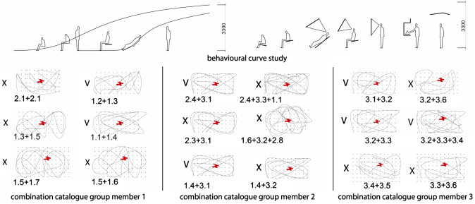
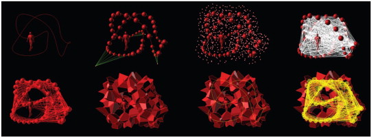
As the title of this workshop states, students are required to work around a 3D point cloud as a real-time interactive interface between their design concepts and the final built form. The design concept was centered on user behavior (physiological and psychological), interaction routines, social behavior as well as ergonomics data pertaining to the physical body. The students were encouraged to develop abstract concepts with regards to movement, scale, patterns, function, structure etc. into 3d curves and/or surfaces (Fig. 1 ), which served as the generator of a redundant quantum point cloud (Fig. 2 ; Fig. 3 ), which was subsequently converted to a collection of 3d Voronoi objects for further selection. The employment of redundancy, as an argument to direct translation from design concept to output, provided opportunities for reflecting on initial design concepts and releasing creativity in a way that was not coined within the initial concept. During this explorative—selection process, students were introduced to the QPC selection tool, which visualizes the global constraints and decision making suggestions in real-time to facilitate the Students design exploration while ensuring the output would always be practical, in terms of structural stability, budget limit and fabrication–construction time limit. This design process can thus be iteratively described in the following manner: firstly blurring the initial design image (design curves and/or surfaces) with a redundant point cloud and then re-creating definite design solutions on top of a vast probability field. By doing so, a non-deterministic translation from design image to design solution is enabled, which upgrades, expands and modifies the initial design image with improvised design exploration.
|
|
|
Fig. 1. Behavioral curve combination catalogs. |
|
|
|
Fig. 2. Design image in form of curve network and point cloud. |
|
|
|
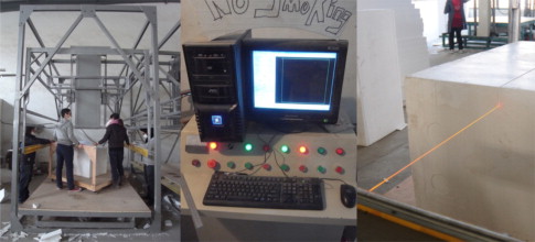
Fig. 3. Hotwire cutter used in QPC workshop. |
3.2. Material and fabrication method
This workshop utilized hotwire cutting of EPS material; a new technique of producing volumetric objects. EPS is a lightweight, cost-effective and recyclable insulation material. Its great strength to weight ratio and easy-to-fabricate property ensures its application in the building industry, especially for low-cost, fast erection projects like the QPC workshop. The hotwire cutter, used in this workshop, is made of a 1-axis moving bed to hold the EPS volume and 1-axis moving head to hold the hot wire. The machine reads a polyline tool path, which controls the movement of both the machine bed and the cutting wire to cut off the material. A good control of the machine movement speed and the electric current which heats up the hotwire is essential to get an ideal balance between production speed and surface smoothness.
3.3. Design constraints
A set of design constraints were introduced to the students to regulate their design proposals, which includes the budget, time management and fabrication constraints that came from the limits of the chosen EPS cutter and the size of the EPS material. The constraint of budget and time management was translated to total amount of EPS volumes to be used, total amount of 3D voronoi objects to be produced and the total surface area of all 3D voronoi objects. These global control parameters have been modeled in the QPC selection tool, which will be discussed later. The fabrication constraint was translated into a density controlling process of the initial point cloud (during the early design stage) and a selection filter that accordingly rules out over-sized objects. Together, this ensured that all remaining points could be produced. As a result, within 8 days, students produced 63 voronoi objects with 28 m3 of EPS material; the total surface area to be coated was 28.31 m2 .
3.4. Schedule
Fifteen days of QPC workshop turned out to be extremely intensive and productive. The design phase, fabrication phase and construction phase were interwoven together to maximize productivity of the entire group. Owing to the enthusiasm of the students and the precise constraint control introduced by the QPC toolset, we strictly follow the initial schedule (Fig. 4 ) and fulfilled the budget and time limitations as set before the workshop.
|
|
|
Fig. 4. QPC workshop schedule. |
4. QPC toolset
QPC toolset comprise a series of design tools specifically developed for this workshop. It has three main components, the Point Cloud Generator (grasshopper), QPC Selection Tool (processing) and Fabrication Optimization Tool (grasshopper). QPC toolset provides technical solutions to data flow from initial design concept till the machine tool path drawing.
4.1. Point cloud generator tool
Point cloud generation tool translates the initial design concept into 3d voronoi objects. This tool is prepared as several grasshopper definitions that were introduced to students at the very beginning. On top of this, students were encouraged to develop their own methods to better support their specific design intention. Fig. 5 shows the design steps of the realized design made by one of the student groups. The tool starts with subdividing a given curve with first level points, and then uses these points to generate second level points. An intensified curve network was made by connecting curve segments to introduce the third level of points. Several key parameters were carefully selected to control the density distribution of the entire point cloud, which was later on converted into a 3D voronoi system3 . The last step of point cloud generation tool is to export computation results into excel files, which will be read by the QPC Selection Tool to recreate the entire geometry and register the typological affiliations. A grasshopper method of filtering out extra-large voronoi cells that do not fit the fabrication limits was introduced before data output, to ensure all points in the QPC Selection Tool can be manufactured.
|
|
|
Fig. 5. Curve to 3d voronoi translation process. |
4.2. QPC selection tool
QPC Selection Tool is the core interactive design computation model of this workshop. It interacts with students by registering their design decisions and provides updated design suggestions according to local situations and global constraints. Students may choose to follow the suggestions, or make informed subjective decisions; the selection tool on the other hand, ensures the co-developed solutions to be always rational with regards to local condition and global constraints. The logic and workflow of the QPC Selection Tool can be illustrated with the following components.
4.2.1. Probability list
The probability list records the probability for each point to be selected, which reveals the evaluation/suggestion provided by QPC selection tool. The selection probability of each point is determined by two factors; its local connectivity and its distance to the closest design curve/surface. From a structural point of view, the more selected neighbors one point has, the more likely it shall be selected to reinforce the structure. From the design point of view, the closer one point is to the original design image, the more likely it shall be selected as it represents better the original design image. Thus two distinct computation intentions can be noticed, one emphasizes local agglomeration while the other emphasizes attraction from dispersed original design image. The balance of these two intentions is achieved by manipulating their factor weights, which is made possible by the Con_weight and Dis_weight slider in the selection tool, thus to address different concerns from the students and to provide customized probability list as design support. Fig. 6 shows the probability patterns with different factor weight setting.
|
|
|
Fig. 6. Factor weight combinations and probability lists. |
The probability list serves as the common database for informed manual design modification and automated design computation. The automated design computation follows the exact sequence of the probability list, while the manual design modification may alter the probability sequence to introduce subjective design considerations other than pure parametric design constraints. For every iteration, both the manual and automated design modification will update the priority list as for the changing introduced local connectivity, however, the two modification methods are registered differently in the computation model. For example, the manually selected points are drawn in red, with their probability value set to 1.0. The automatically selected points are drawn in white with their probability value unchanged; see left screen shot of Fig. 6 .
4.2.2. Local and global constraints
A set of local and global constraints is imbedded in the QPC selection tool, which, represent the parametric boundary for the design exploration. The local constraint is introduced by the selected construction method; gluing EPS objects together. The global constraints are introduced by the general limits of cost and time management. These constraints have to be kept intact to reveal practical design solutions. In case of a conflict between design constraints and current design solution, visual feedback is provided to force an informed design modification.
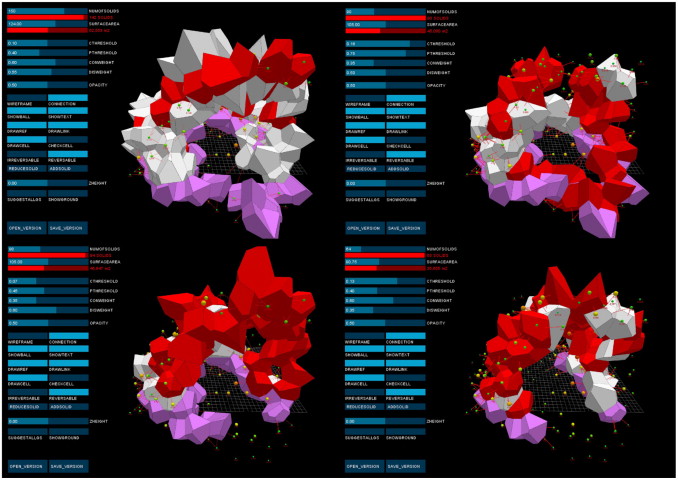
Local constraint is modeled as the threshold of total confirmed contacting surface area (CThreshold) for each voronoi object, which specifies how well the object is supported by its neighbors. By setting up this threshold (0.1 m2 ), and checking the “checkcell” option, as in the case of the left screenshot in Fig. 7 , all voronoi objects that have total confirmed surface contacting area below this threshold will be identified, as shown in blue color. This zoom in of problematic objects, requires students to either add more contacting objects to support this weak/floating object, or simply delete it.
|
|
|
Fig. 7. Local and global constraints. |
The global constraints are modeled as two parameters, numofsolids and surface area. The numofsolids parameter sets the limit for the number of voronoi objects to be selected/fabricated, so as to ensure a practical design solution that is within the budget and time management limits. The surfacearea parameter sets the limit for total surface area that has to be coated, so as to ensure surface coating cost will be under control. The right side screenshot of Fig. 8 , shows the screen lockup after breaking the global constraints.
|
|
|
Fig. 8. Point cloud connectivity pattern. |
4.2.3. Supportive functions
Several supportive functions have been tailored to the need of QPC selection tool, and proven to be highly helpful as an interface between students and the design computation models. The supportive functions can be concluded in three groups, visualization functions, typological functions and ground support functions.
Visualization functions include displaying voronoi wireframe for all candidate points, displaying probability values with sphere indicators and/or plain text, highlighting mouse over point, displaying reference world coordinate and drawing selected voronoi objects as a solid mesh with controllable transparency. A smart combination of visualization functions presents only the relevant information for current design concern, thus reducing the visual complexity to facilitate an efficient communication between students and the complex point cloud model.
The typological connectivity is a static connectivity pattern that records all surface contacting connections between all voronoi mesh cells. It is computed at the voronoi generation stage and imported to the QPC selection tool. The typological connectivity is mainly used for the following two purposes; The first one is to check the structural stability, as shown in the left screen shot of Fig. 8 , the color and thickness of lines connecting paired points indicate the connection strength, and are determined by the shared contacting surface area of paired points. The second one is to indicate the typological neighbors of any targeted point, as shown in the right screen shot of Fig. 8 , while holding the mouse over points, its connectivity pattern will be displayed to help with quickly checking the neighboring condition of this point.
Ground support functions compute and identify all voronoi meshes that are touching ground. A controllable virtual ground plane is introduced here, which allows an easy search for the ideal ground cutting height. Fig. 9 shows the effect of lowering down and lifting up the virtual ground plane. All ground touching meshes are displayed with transparent purple color, which help the students to quickly discover the ground touching selection range and come up with a reasonable load distribution pattern.
|
|
|
Fig. 9. Ground support functions. |
4.2.4. Computation automation
QPC selection tool presents two design automation modes based on different ways of applying the probability list. The first automation mode presents a stepwise solution searching strategy, meaning for each and every automation step, the point with highest probability value will be selected. This will update the connectivity factor for its connected points, thus producing a new probability list as the base for the next round automation. The automation history is recorded for this automation mode, which allows going back and forth between automation steps, so as to facilitate quick design solution comparison. Thus, in the QPC selection tool, this automation mode is called the reversible mode.
The second automation mode changes point state for a portion of the probability list. This is made possible by using the Pthreshold slider, which marks a target priority value threshold and then converts all points that have probability value higher than it into selected points, and release all points with lower value. Similar to the reversible mode, any modification of point state will produce a new probability list as the initial condition for next stage, thus applying the same Pthreshold value with two different initial conditions will produce different point state pattern. As there is no automation history recorded here, this automation mode is, in principle, is an irreversible process, and is thus called as irreversible mode.
The modeling intention behind these two different automation modes is to keep the reversible mode straightforward for design fine-tuning, while irreversible mode for quick design solution generation. It has been noticed that during the workshop, students started with trying out different solution patterns generated by irreversible mode, then continuing with manual selection and reversible automation.
4.2.5. Design interaction
Design interaction is the main driver of QPC selection tool, which exchanges design intention and design constraints between designer and design computation model. Interaction to its strict definition describes a mutual stimulation process of two entities. QPC selection tool is modeled as a semi-automatic design computation solver that provides visual feedback, gathers design input and generates multiple ranked solutions all in real-time, which together informs and stimulates designers for quick heuristic design explorations with precise control of design parameters, Fig. 10 . The various functions and automation modes provided by QPC selection tool proved to be efficient in establishing an interactive relationship between design computation model and designer, and upgraded design computation models from a mere computation solvers to a design partner.
|
|
|
Fig. 10. QPC Design explorations. |
4.3. Fabrication optimization tool
QPC fabrication tool optimizes voronoi cell orientation and then produces automated fabrication drawing and machine tool path for all confirmed voronoi objects. To better illustrate the optimization process and drawing automation, a brief explanation of machine fabrication procedure is necessary.
4.3.1. Fabrication of EPS voronoi objects with the hotwire cutting machine
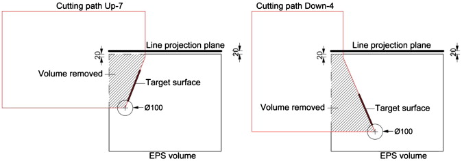
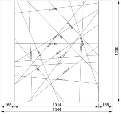
The EPS voronoi objects are produced with a series of planar cutting of the original EPS block. As a 3D convex geometry, voronoi object can be easily cut out with its component surface planes. Fig. 11 illustrates such planar surface cutting system, which is made of a target voronoi surface, a hotwire cutting path and a line projection plane. The hotwire cutting machine directs the movement of its hotwire according to the cutting path drawing, by means of combining the two 1-D movement of its machine bed and hotwire gate. The cutting machine needs a clear reference to align its hotwire with the EPS volume first to cut out the target surface. The line projection plane, Fig. 12 , serves as the alignment reference. It records all surface–surface intersections between itself and the voronoi sub-surfaces. The index correspondence of the intersection projection line, machine-cutting path and target surface are carefully checked during the actual machine operation.
|
|
|
Fig. 11. Machine tool path for cutting out voronoi surfaces. |
|
|
|
Fig. 12. Line projection plane with intersection marks. |
4.3.2. Voronoi orientation optimization
Voronoi orientation optimization searches for an ideal orientation for placing the voroni objects within EPS blocks by observing two evaluation criteria. The first one makes sure that the target voronoi object can be produced within one single EPS block and its orientation will align with the machine limits, while the second one minimizes the material waste. The orientation optimization tool is made as a grasshopper definition, which takes the rotation angle combination of a voronoi object around the three world coordinates as its genome and the material usage as its fitness. A checking process takes place before the rotation angle combination is to be evaluated for fitness, which filters out the genome combinations that fail to ensure a feasible production.
The checking filter considers two conditions. The first one is if all voronoi sub-surfaces intersect with the line projection plane, while the second one is if the resulted minimal wrapping box of the voronoi object is within the material and fabrication limits4 . Each genome combination results in a wrapping box of target voronoi object, which resembles the actual EPS material volume needed to produce this object, while only the combinations that may pass the checking filter will pass the wrapping box dimensions to the fitness evaluation phase.
The evaluation phase takes the wrapping box edge length in X direction as the material usage indicator. As the general optimization strategy lies in maximizing the Y and Z dimension of the wrapping box to the fabrication limit, so as to buy more reduction for the X dimension. The reason of choosing X direction to optimize is because the X dimension of the raw EPS volume is the longest compared to the other two dimensions, thus, by optimizing for the X dimension, it is hoped to pile more wrapping boxes within one raw EPS block. As it actually turned out, one EPS block can always hold 4–5 wrapping boxes, in this way, the material usage efficiency was greatly improved.
4.3.3. Drawing automation
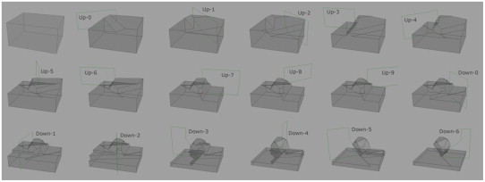
With the optimized voronoi object orientation, a set of grasshopper operations are carried out to automate fabrication drawing and material tool path making, which have to be paired together and indexed with a rotation sequence. Fig. 13 shows the cutting sequence for a test voronoi object, the rule behind it is to cut out the surfaces which are facing up-side first, then cut out the down-facing surfaces from the smallest to the biggest size. This means that the largest down-facing surface will be cut out last, so as to minimize the material displacement introduced by the hotwire removal process.
|
|
|
Fig. 13. Cutting sequence. |
5. Fabrication and construction
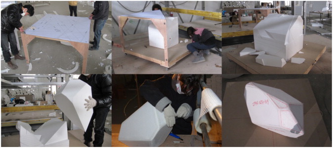
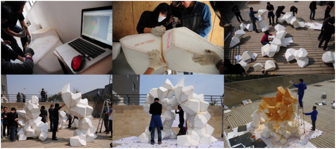
The fabrication and construction phase very well followed the workshop schedule. On average the fabrication of each EPS voronoi object took about 100 min. A rotation table made of two triangular pieces was devised to facilitate the hotwire cutting. The line projection drawing was fixed on a tabletop, while the rotation table was put on a movable plinth. Thus an easy alignment between intersection line projection and hotwire was achieved (Fig. 14 ). Edge and corner smoothing were later performed on every voronoi object. Glass fiber wrapping was subsequently applied to provide extra stiffness. A careful indexing of voronoi objects and their contacting surfaces was applied as the the last step of the fabrication stage.
|
|
|
Fig. 14. Fabrication process. |
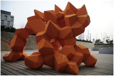
The EPS object assembly is done with special EPS glue. The 63 EPC objects were firstly assembled into 7 groups, and then put together on site. Thus students were able to work in parallel to speed up the assembly process. A rhino model was made to allow easy browsing of object index and surface index per group. The surface coating was done with a professional company with stone lacquer. Fig. 15 shows the assembly and coating sequence, with the resulted pavilion in Fig. 16 .
|
|
|
Fig. 15. Assembly and coating. |
|
|
|
Fig. 16. QPC pavilion. |
6. Conclusions
Aimed at creatively fusing objective design constraints with subjective design intentions, and quickly delivering a full-scale low-cost pavilion, the QPC workshop utilized a set of parametric tools to facilitate heuristic design exploration with strict design constraints. Among these, QPC selection tool revealed the potential of interactive design computation modeling. Design interaction, as discussed in this paper, argues for an interactive relationship between designer and design computation models, which synchronizes the efficiency of deductive reasoning from computation devices together with the creativity of associative reasoning of human designers. To establish such an interactive relationship, quantum paradigm is introduced to address a new language in computation modeling. The key difference between classical design computation modeling and this approach is the shift in design mentality, which replaces the single-best paradigm with a range of sufficient solutions that are ranked with probability and presented in parallel. This mentality shift legitimates a new kind of computation questions to be asked, which eventually opens up a whole new research field.
Three observations can be concluded from the success and deficiencies of the QPC workshop. The first one is that material and fabrication constraints have to be precisely modeled before the design stage. An in-depth study of the material and fabrication limitation is the key factor for realizing design freedom while promising practical solutions. As for the QPC workshop, these constraints come from the standard EPS block sizes, machine movement limits, machine size limits, and the conflict between 3D convex object fabrication and the 2 dimensional movement of the cutting machine. A good understanding of these objective constraints and their inter-relationship eventually leads to a exact figure of maximum fabrication size limit, and thus informs the students with a rational point cloud density in the very early design phrase. The second observation is that it is possible to achieve economical efficiency and heuristic design exploration simultaneously in the same interactive design computation model. As for the QPC workshop, the economical efficiency refers to smart management of budget, time limit and material usage, while heuristic design exploration refers to freely altering design development with subjective design intention. The QPC tool set allows the designer to quickly explore different design configurations without sacrificing strictly defined economical efficiency, which is the fundamental advantage of quantum design paradigm compared to automation oriented modeling paradigm. The third observation is the severe tolerance problem in the built up pavilion. The tolerance problem comes from the imprecise production of single EPS voronoi objects. To fulfill the ambition of producing 3D convex objects with a limited 2D hotwire cutter, a physical rotation table is used in this workshop, which requires manual alignments of hotwire to intersection projection lines. Unlike a CNC procedure, this manual workflow is very sensitive to the skill and fatigue of the students. The biggest tolerance discovered in the final model is 2 cm, which is far beyond the 2 mm cutting tolerance5 promised by a true CNC hotwire cutting procedure. Although the tolerance problem was later fixed by adding additional layer of EPS slabs or sanding off extra material, the danger of combining CNC and manual workflow for a precise production is obvious, and should be avoided for precision sensitive projects.
The QPC workshop, as a joint education program, successfully fulfilled its educational purpose of introducing both the elementary parametric design/optimization knowledge and the advanced interactive design modeling. The resulted full-scale model is designed, fabricated and constructed within 15 days and with the total material, fabrication and surface coating cost precisely controlled under 20,000 RMB, which clearly proved the strength of the parametric design approach. As a case study of interactive design computation modeling, the QPC workshop proved the potential of quantum design paradigm and interactive design computation modeling for realizing a flexible design exploration with precise design constraints, thus suggesting a new research frontier for parametric design.
Acknowledgements
The QPC workshop was generously financed by the School of Architecture & Urban Planning, Nanjing University, China . Professor Wowo Ding, Guohua Ji and Dr. Ziyu Tong made valuable contribution to the success of QPC workshop in terms of workshop management, realization project selection and fabrication support. The student participants include: Mo Chen, Zhijie Dong, Zejing Song, Ye Tian, Han Wang, Xing Wang, Yang Yang, Fang Huang, Mengyuan Duan, Xiaoxuan Hu, Zhifeng Xie, Zhouya Shen, Aurora de Liefde, Carlos Abel Saenz, Donald, Pattinama, James Yapi, Ismael Quevedo Medina, Matthijs la Roi, Wouter Kroon. The realization design was originally developed by Matthijs la Roi, Yang Yang, Xie Zhifeng, who also hold the credit for Fig. 1 , Fig. 2 ; Fig. 5 .
References
- Arida, 2002 Arida, A., 2002. Quantum city. Architectural Press, Oxford.
- Menges & Ahlquist, 2011 Feng, H., 2009. 18-19 April. Quantum architecture: an indeterministic and interactive computation design system. Paper presented at the Second International Conference on Critical Digital: Who cares? Harvard University, Graduate School of Design.
- Feng, 2009 Flake, G.W., 1998. The Computational Beauty of Nature Computer Explorations of Fractals, Chaos, Complex Systems and Adaptation. MIT Press, Cambridge.
- Flake, 1998 Menges, A., Ahlquist, S., 2011. Computational Design Thinking. John Wiley & Sons, Chichester, UK.
- Oosterhuis, 2011 Oosterhuis, K., 2011. Towards a New Kind of Building Tag, Make, Move, Evolve. NAi Publishers, Rotterdam.
- Oosterhuis, 2011 Oosterhuis, K., Xia, X., Feng, H., 2011. iA 4. Quantum Architecture. Jap Sam Books, Heijningen.
Notes
1. As for this paper, interactive refers to a circled communication process that involves mutual understanding and unexpected stimulation, which should be carefully distinguished from the concept of reactive. A rigorous terminology for conversation, interaction, environment and participation can be found from Gordon Pasks conversation theory.
2. Wave–particle duality is the concept that all matter and energy exhibits both wave-like and particle-like properties. A central concept of quantum mechanics, duality addresses the inadequacy of classical concepts like “particle” and “wave” in fully describing the behavior of small-scale objects. http://en.wikipedia.org/wiki/Wave-particle_duality
3. The conversion from point cloud to 3D voronoi objects was made by calling qhull library from a customized c# component in grasshopper. The initial qhull-grasshopper connection was developed by Dimitrie Stefanescu (www.improved.rof ), one of HyperBODY master students. This initial connection was later on enhanced by the author to fit the need of QPC workshop. The enhanced version can be download at http://www.makeahybrid.org
4. The raw EPS block used in this workshop comes with a standard size of 2.03 m×1.23 m×0.62 m, with a size tolerance of 0.3 cm. The machine used in this workshop can make horizontal movement of 1.2 m (machine bed), and vertical movement of 0.8 m(hotwire gate), which the actual cutting height of 0.6 m. Thus the maximum voronoi object wrapping box is set as 1.15 m×1.18 m×0.55 m.
5. This tolerance is introduced by melting effect of EPS material over heated hotwire, and has been anticipated and taken into consideration in the design process.
Document information
Published on 12/05/17
Submitted on 12/05/17
Licence: Other
Share this document
Keywords
claim authorship
Are you one of the authors of this document?
