1 Introduction
The use of carbon fibre reinforced polymers in primary and secondary aircraft structures has significantly risen in the latest few decades, mainly due to their excellent fatigue endurance and high specific strength when compared to the more conventional materials. [1] Nowadays, research efforts in this area are focused on making these materials more affordable, by means of the implementation of advanced manufacturing technologies, and improving their mechanical properties, through the investigation of new matrix-fibre combinations.
The work presented here is framed in SHERLOC, [2] a European Research Project which pursues the development of a Structural Health Monitoring (SHM) system for a regional aircraft fuselage made of composite materials. The SHM system which is being developed is based on different sensor technologies (fibre optics, piezoelectric, hybrid and magnetostrictive) for the detection and repair of the damage in the aircraft. This concept aims to move from the current maintenance system based on scheduled revisions towards to a maintenance system based on the real conditions of the structure (Condition Based Maintenance, CBM).
One of the objectives of SHERLOC project is to achieve the implementation of this SHM system on the most advanced composite materials which currently exist. The verification and validation process for the SHM system consists on a testing methodology where the test complexity is progressively increased (known as ‘Building Block Approach’). The first stage of this process consists on the determination of material allowable under different types of simple loads, such as tension, compression or shear. The present work covers the mechanical characterization at coupon level of different carbon-fibre reinforced polymers (CFRP). A comparative analysis is performed between traditional materials and promising materials such as Non-Crimp Fabrics and composites including advanced elements, such as Carbon Nanotubes (CNTs) [3] or a damping veil. Once fundamental mechanical properties are assessed for each material, a down-selection methodology will be followed to reach the next step of validation complexity.
2 Materials and Methods
2.1 Materials
Four different thermoset composites were mechanically characterized. As reference material, a typical aerospace composite provided by Hexcel was selected, named M21/34%/194/T800S. The material consists of unidirectional pre-pregs of an epoxy matrix (M21) with a resin content by weight of 34%, which is reinforced by carbon fibres (T800S) with fibre weight of 194 gsm. In this work, this material is identified as M1. The specimens of this material were manufactured by means of manual hand lay-up (HLU), followed by autoclave curing at 180 ºC and 7 bar. Typical autoclave bagging process steps have been followed in order to assure correct consolidation and homogeneity of resin curing.
The second material is also based on an epoxy resin (PRISM EP2400), but reinforced by dry Non-Crimp UD Carbon Fabric (NCF) U-C-PB-209g/m²-1220mm using fibre from TENAX (TENAX-E IMS65 E23 24K). Cytec applies the binder (Momentive Epikote Resin 05311) and Polyester (PES 48 dtex SC) as stitching. This material (hereinafter called M2) is manufactured through an innovative process known as Liquid Resin Infusion (LRI), which is based on the injection of the liquid resin in a preform of fibres placed in a mould. Resin impregnation and curing is performed in a standard oven under the application of vacuum (without need of autoclave equipment). The proper design of the infusion process ensures that the resin flows homogeneously through the part.
The effect of embedding the fibre optics sensors in different laminates of materials M1 and M2 was studied previously. [4]
The material named as M4-EME is similar to the material M1, its matrix being modified by including a reinforcing dispersion of carbon nanotubes (CNTs), M21+CNT/T800S. Nano-reinforced composite materials are quite costly and may not out-weight by achievable benefits. [5] Likewise, it is also important to consider that manufacturing of the CNT-reinforced pre-pregs arises safety concerns with respect to the use of nano-powders.
In the same way, the material M4-VEIL is the material M1 which incorporates a viscoelastic veil (SMACWRAP®), of around 0.1 mm thickness, with the purpose of improving its damping capacity against impacts. This veil is not placed in the middle of the laminate. Therefore, in the tests where different tensional modes are distinguished at both sides of the specimen, the side of the specimen which has the damping veil closer will be subjected to compressive stress.
2.2 Ageing
During its service life, aircraft is exposed to high temperatures and high levels of humidity. Properties of composite materials may be affected as a consequence of moisture absorption and high temperature, In order to evaluate the degradation of their mechanical properties, an environmentally conditioned testing scenario is considered.
Thus, two different types of test series are covered in this campaign. On the one hand, room temperature (RT) tests (25 ± 2 ºC, 50 ± 5 % R.H) are conducted on specimens with as-fabricated moisture content. On the other hand, there are parallel test series which are conducted on specimens that have been previously conditioned. These are known as Hot Wet (HW) tests. The conditioning parameters are usually fixed according to the conditions to which aircraft structure may be subjected during its service life. This commonly means an equilibrium moisture weight in an 85% relative humidity environment and a temperature of 70 ºC. Nevertheless, in order to achieve a lower completion time for the testing campaign, especially for thermoset materials which involve long environmental conditioning times, accelerated conditioning has been carried out. It has been proved that increasing temperature leads to a faster conditioning process due to the higher moisture absorption in the early stages, which allows reaching moisture equilibrium in a shorter period. Thus, conditioning has been performed at higher temperature (80 ± 3 ºC), under the same relative humidity (85 ± 5 %). It was checked that glass transition temperatures for tested materials were significantly higher than the accelerated conditioning temperature. In this way, a decrease of conditioning periods was achieved, speeding the rate of testing, as well as it slightly increases the safety factor for the assessed mechanical properties.
In order to maintain the environmental conditioning, static HW tests were conducted under controlled temperature (70 ºC) using thermocouples inside a climatic chamber.
The control of humidity absorption in the test specimens was carried out according to the standard ASTM D5229/D5229M, [6] using three witness specimens (known as travellers) with the same thickness and material as the test specimens, and dimensions of 25 x 25 mm. According to the ASTM standard, effective moisture equilibrium is achieved when the average moisture content of the traveller specimen changes by less than 0.020% for two consecutive readings within a span of 7±0.5 days.
2.3 Mechanical tests
One of the objectives of this test campaign is to establish the fundamental material properties for subsequent use with structural analysis and design techniques. To this end, a high number of standard tests were conducted on small specimens known as coupons.
In Table 1 the most important mechanical properties that have been studied in this experimental coupons test campaign are summarized. The test campaign covers a wider range of experimental testing including fatigue and crack growth behaviours analysis. This study is focused on most relevant mechanical properties that enable comparative analysis and future down-selection. For tension and compression tests, unidirectional laminates were used. Tensile and compressive properties were obtained from unidirectional laminates where fibres are oriented in 0º or 90º directions. If the fibres are aligned in the loading direction, this represents an ultimate test condition where the stresses developed will be higher than possible with any other layup of the same fibres. Conversely, if the fibres are at 90° to the loading direction, the test piece is the weakest. ±45º laminates were used to study in-plane shear properties. Pull-through resistance and residual strength properties (compression after impact, CAI, and tension after impact, TAI, tests) were performed on multidirectional laminates. The stacking sequence for these laminates, MD1, was (6/2/2/2) [+45/-45/02/90/0]s.
For each test series, 5 specimens were tested under quasi-static loading, in order to obtain a b-basis statistical results set. Two batches of manufacturing were tested for those materials not counting with Certificate of Conformity (CoC), M4-EME and M4-VEIL. Thus, likely increases of the coefficient of variation due to variability factor in manufacturing quality are considered.
| Test | M1 | M2 | M4-EME | M4-VEIL |
| Tension | 0º, 90º | 0º, 90º | 0º, 90º | 0º, 90º |
| Compression | 0º, 90º | Modulus 0º, 90º | 0º, 90º | 0º, 90º |
| In-Plane Shear | ±45º | ±45º | - | - |
| Pull-through | - | - | MD1 | MD1 |
| TAI | MD1 | MD1 (RT) | MD1 | MD1 |
| CAI | MD1 | MD1 | MD1 | MD1 |
2.3.1 Tension tests
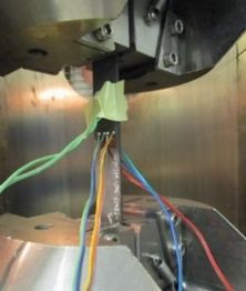
The objective of these tests was to determine the properties of tensile strength, laminate stiffness, which is assessed through the elastic modulus, and the Poisson coefficient. Tension tests were performed according to ASTM D3039/D3039M standard. [7]. RT tests were performed through a Universal Testing Machine 8801, equipped with a load cell up to 100 kN. HW tests were carried out by means of a Universal Testing Machine Zwick Z100, equipped with a load cell up to 100 kN. In Figure 1, the set-up for HW tests is shown. Glass fibre end-tabbed specimens were used to conduct these tests. Both 0º and 90º-oriented specimens were monitored through strain gages. In particular, bi-directional strain gages were used for 0º specimens. This type of strain gages allows to measure longitudinal and transversal strains at the same time. Additionally, back-to-back strain gages were mounted on the first specimen of each test series to check load introduction alignment.
2.3.2 Compression tests
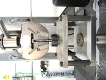
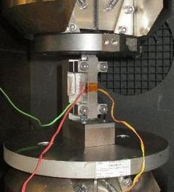
Compressive properties with 0º-unidirectional laminate were assessed through different standards. On the one hand, compressive modulus was obtained following ASTM D695 standard. [8] Dog-bone specimens instrumented with strain gages were used. Back-to-back strain gages were mounted on all the specimens of each test series to check there was no buckling or bending along test execution. In all the tests, percent bending was lower than the maximum valid value according to the standard. On the other hand, compressive strength was assessed using EN2850-B end-tabbed specimens. [9] For 90º, specimens with the geometry defined in the standard ASTM D695 were used for the evaluation of both compressive modulus and strength. ASTM tests under RT conditions were performed through a Universal Testing Machine 8801, equipped with a load cell up to 100 kN. The rest of the tests were carried out by means of a Universal Testing Machine Zwick Z100, equipped with a load cell up to 100 kN. In Figure 2, the set-ups for HW tests are shown.
|
|
| a | b |
2.3.3 In-Plane Shear tests
These tests aim to assess in-plane shear strength of composite materials. To this end, static tension tests were conducted on end-tabbed specimens whose laminate is ±45°, according to the standard ASTM D3518/D3518M. [10] Bi-directional strain gages were used to measure longitudinal and lateral strains. Results of the tests are valid up to maximum of 5% of engineering strain, since higher levels of strain are evidence of an alignment process of the fibres in the loading direction. The tests machines and tooling used for these tests are similar to the ones used for tension tests.
2.3.4 Pull-through resistance tests
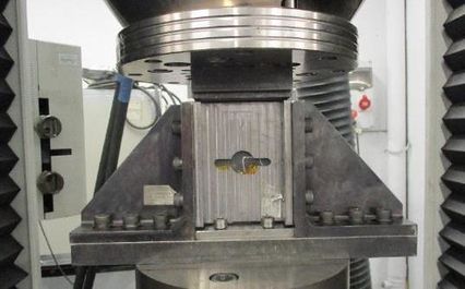
Pull-through resistance tests were conducted according the standard ASTM D7332/D7332M. [11] The test fixture shown in Figure 3 was used.
2.3.5 Residual strength tests
The strength of damaged specimens under compressive and tensile loads was evaluated. An impact calibration campaign was performed in order to assess the impact energy levels which are necessary to produce barely visible impact damage (BVID). An additional requirement was impact should not penetrate all the specimen thickness. An impact tower equipped with a steel impactor of 16 mm diameter was used. Regarding M4-VEIL specimens, they were impacted on the side of the specimen which is closer to veil. Except for M1-TAI specimens, impact boundary conditions were the same for all the test series. Finally, impact energies shown in Table 2 were selected to obtain BVID without penetrating all specimen thickness, for both compression and tension after impact tests.
| M1 | M2 | M4-EME | M4-VEIL | |
| I1 (J) | 10 | 25 | 10 | 10 |
| I2 (J) | 14 (CAI) | 35 | - | - |
Compression After Impact tests (CAI) require to perform an impact on the specimen before compression test is conducted. This impact was performed according to the test method described in ASTM D7136/D7136M. [12] Since standard does not specify an order for impact and conditioning, impacts are executed first and then specimens are conditioned with the purpose of maintaining comparability between the same impact levels for both with and without conditioning tests.
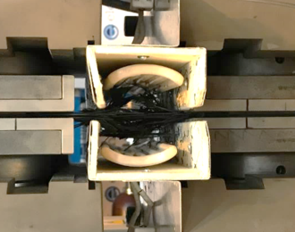
Compression After Impact tests were performed according to ASTM D7137/D7137M standard. [13] The specimens laminate configuration for impact damage experimental tests is representative of the airframe component they are expected to be part of. Due to this, specimen thickness is lower than recommended by the standard. As it can be seen in Figure 4, an anti-buckling device was installed on specimens with the purpose of stabilizing any buckling produced and induce failure due to pure compression through the impacted section of the specimens.
Additionally, an experimental procedure was developed to conduct tension after impact (TAI) tests. Specimens were impacted by means of an impact tower, at energy level of 10 J. Previously, a calibration impact campaign had been performed to select the impact energy level leading to BVID.
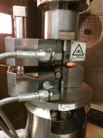
These tests were conducted by means of Universal Testing Machine IBERTEST UFIB-1000E, equipped with MTS hydraulic actuators and MTS load cell, both with capacities up to 500 kN. In Figure 5, the set-up for static tests conducted under HW conditions is shown. Since it was not possible to attach the air oven to the IBERTEST testing machine, heating plates were mounted around the specimen in order to maintain the HW test conditions.
3 Results and Discussion
3.1 Tension tests
Tension tests had one only limitation during 0º-tests: strain gages achieve full scale due to large strain levels. Nevertheless, it is not necessary to use strain gages that are able to achieve a wider range of strain in order to determine the stiffness and Poisson coefficient of the material. Elastic modulus and Poisson coefficient (where applicable) have been calculated between the longitudinal strains values of 0.001 and 0.003.
| Tensile strength (MPa) | Tensile modulus (GPa) | Poisson Coefficient | ||||||||||
| RT | HW | RT | HW | RT | HW | |||||||
| CV (%) | CV (%) | CV (%) | CV (%) | CV (%) | CV (%) | |||||||
| M1 | 2850 | 4 | 2800 | 5 | 138 | 2 | 143 | 2 | 0.311 | 16 | 0.314 | 2 |
| M2 | 1520 | 8 | 1710 | 9 | 112 | 3 | 113 | 7 | 0.345 | 12 | 0.287 | 16 |
| M4-EME | 2370 | 4 | 2500 | 2 | 134 | 6 | 139 | 1 | 0.332 | 5 | 0.310 | 5 |
| M4-EME-B2 | 2630 | 4 | 2430 | 2 | 130 | 2 | 133 | 3 | 0.305 | 9 | 0.278 | 8 |
| M4-VEIL | 2280 | 3 | 1900 | 4 | 127 | 1 | 136 | 3 | 0.323 | 8 | 0.301 | 2 |
| M4-VEIL-B2 | 2170 | 3 | 1760 | 7 | 125 | 5 | 124 | 6 | 0.278 | 9 | 0.284 | 9 |
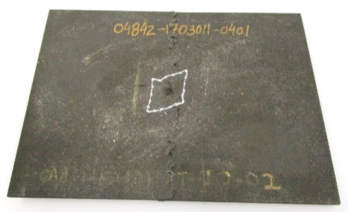
In 0º-tests, failure mode was explosive (XMV) for all the materials. An example of specimen failure corresponding to M1 material is shown in Figure 6.
As it can be extracted from Table 3, in 0º-tension tests, the highest strength is achieved for unidirectional epoxy material (M1), with an average value of 2850 MPa at RT-conditions, which is slightly reduced in HW-conditions (2800 MPa).
By comparing the behaviour of reference material (M1) with LRI coupons (M2), it can be stated that tensile strength is significantly lower for material M2. Nevertheless, it should be noted that the higher strength for LRI coupons at HW conditions reflects a likely slight fibre misalignment in the fabrication process of RT coupons, which could reduce this difference. Tensile strength is considerably reduced (RT: 17%, HW: 13%) when the resin matrix includes a CNT-dispersion, and significantly reduced (RT: 24%, HW: 37%) when an acoustic damping veil is included, taking as reference, for both versions of the M4 material, the batch for which lowest average strength has been obtained. Ageing does not significantly affect tensile strength properties, except for material M4-VEIL, where a decrease of about 20% is obtained.
Regarding the stiffness of the assessed materials, there are not relevant differences between modulus obtained for M1 and its modified versions. Instead, as it occurred for tensile strength, higher differences are obtained between M2 and M1. Regarding modulus, ageing has not a noticeable influence on the test results.
High level of dispersion in Poisson’s ratio was obtained for materials M1 at RT conditions and M2 both at RT and HW conditions. This may be justified by the high sensitivity of Poisson ratio to specimen width, which for this case is just 15 mm in order to maintain failure load levels into a range for which universal test machines (UTMs) can operate.
When fibres are 90º-oriented with respect to the loading axis, the matrix is the resistant material. Thus, as it can be expected, the results of these tests are lower than those obtained for 0º-tension tests (Table 4). In this sense, it could be stated that thermoset matrix used for material M1 can undergo higher stress levels than M2 matrix. Moreover, failure is produced along specimen width and perpendicular to its length, as it is shown in Figure 7. Effect of ageing is more pronounced for 90º-tension specimens (decrease of 40% of compressive strength for material M1 and 51% for M2), which implies that a higher degradation of matrix properties is produced by conditioning process when it is compared with the resistant material at 0º, the fibres.
| Tensile strength (MPa) | Tensile modulus (GPa) | |||||||
| RT | HW | RT | HW | |||||
| CV (%) | CV (%) | CV (%) | CV (%) | |||||
| M1 | 56.6 | 6 | 34.2 | 8 | 8.63 | 3 | 7.42 | 0.4 |
| M2 | 46.5 | 6 | 23.0 | 7 | 7.62 | 1 | 7.27 | 1 |
3.2 Compression tests
Results of compression tests are shown in Table 5. Failure occurred in specimen span, as depicted in Figure 8. From the results of these tests, it can be concluded that the insertion of the damping veil remarkably affects the compressive strength, decreasing this property in 39% for both RT and HW tests. The negative influence of CNT-reinforced matrix on compressive strength is lower, but also significant (RT: 12%, HW: 39%). Furthermore, ageing has a noticeable effect on compressive strength, decreasing this property from 10% (M1) up to 29% (M4-EME).
Compressive modulus tests were conducted up to the strain levels required to determine this property. This involves that these tests were not performed necessarily up to failure, as shown in Figure 9.
It can be observed that there are not remarkable differences for the compressive modulus between the assessed materials, being less than 10% when comparisons are established with material M1. In this case, ageing effect is not significant.
| Compressive strength (MPa) | Compressive modulus (GPa) | |||||||
| RT | HW | RT | HW | |||||
| CV (%) | CV (%) | CV (%) | CV (%) | |||||
| M1 | 1109 | 13 | 994 | 0.5 | 141 | 4 | 138 | 2 |
| M2 | - | - | - | - | 127 | 1 | 128 | 2 |
| M4-EME | 972 | 8 | 690 | 0.7 | 132 | 2 | 136 | 1 |
| M4-EME-B2 | 985 | 5 | 736 | 0.4 | 134 | 3 | 135 | 1 |
| M4-VEIL | 779 | 5 | 629 | 0.8 | 133 | 7 | 129 | 4 |
| M4-VEIL-B2 | 681 | 5 | 610 | 0.6 | 149 | 5 | 136 | 3 |
With respect to 90º-compression tests (Table 6), it can be concluded there are no remarkable differences between the compressive modulus obtained for materials M1 and M2. Ageing affects to compressive strength of material M1 with a decrease of 27%, while it does not have a noticeable impact on compressive modulus.
| Compressive strength (MPa) | Compressive modulus (GPa) | |||||||
| RT | HW | RT | HW | |||||
| CV (%) | CV (%) | CV (%) | CV (%) | |||||
| M1 | 158 | 4 | 115 | 2 | 8.72 | 2 | 8.45 | 3 |
| M2 | - | - | - | - | 8.20 | 4 | 8.79 | 3 |
3.3 In-Plane Shear tests
For both assessed materials (M1 and M2), strain gages failed before the maximum valid level of engineering shear strain (5%) was achieved. Thus, the tests were performed up to failure and maximum shear stress shown in Table 7 corresponds to specimen failure (as depicted in Figure 10). Shear modulus was calculated over a 4000±200 µε engineering shear strain range, starting with the lower strain point of 1500 µε (HW) and 2000 µε (RT).
It should be highlighted that maximum shear stress is higher for material M1 in 34% (RT) and 17% (HW), while difference in modulus is only significant at HW conditions. Ageing has a remarkable negative impact on both shear stress (25%) and modulus (12%) for material M1, as well as a decrease of shear modulus (21%) for material M2.
| Maximum shear stress (MPa) | Shear modulus (GPa) | |||||||
| RT | HW | RT | HW | |||||
| CV (%) | CV (%) | CV (%) | CV (%) | |||||
| M1 | 125 | 2 | 93.5 | 1 | 4.29 | 3 | 3.79 | 8 |
| M2 | 82.7 | 3 | 77.4 | 2 | 4.13 | 3 | 3.25 | 2 |
3.4 Pull-through resistance tests
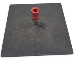
Regarding pull-through resistance tests, it was appreciated a homogeneous failure mode for all the tested specimens. As it can be observed in Figure 11a, it consisted on laminate Pull-through in the top of laminate hole (identified as PLT according to the standard). Additionally, ultrasonic inspections conducted after testing also revealed delamination around the hole. These delamination were visually observed for M4-EME specimens, where it can be identified a second failure mode consisting on delamination in the bottom of the laminate hole (DLB, Figure 11b).
|
|
| a | b |
The results of these tests are shown in Table 8. From the values of maximum pull-through forces, it can be extracted that pull-through resistance of the CNT-reinforced matrix composite is significantly higher than M4-VEIL pull-through resistance, with differences of 42% and 27% when tests are performed under RT and HW conditions, respectively. Likewise, although ageing affects both materials, a higher impact is noticed in the case of M4-EME specimens, where ageing involves a decrease of maximum Pull-through force of 17%.
| Maximum Pull-through force (kN) | ||||
| RT | HW | |||
| CV (%) | CV (%) | |||
| M4-EME | 4.93 | 2 | 4.10 | 4 |
| M4-EME-B2 | 4.60 | 6 | 3.85 | 4 |
| M4-VEIL | 3.29 | 1 | 3.09 | 3 |
| M4-VEIL-B2 | 3.42 | 4 | 3.19 | 3 |
3.5 Residual strength tests
3.5.1 Compression After Impact tests
Test series of materials M1, M4-VEIL and M4-EME were impacted at 10 J, but no valid failure was obtained for them. This low-energy level for impacts had been selected for the sake of assessing the effect of BVID on the mechanical behaviour of the materials. The rationale of this assessment is to apply SHM sensors which are able to detect BVID in the structure made of the selected material. Nevertheless, the measured delaminated areas were compared and differences between the materials could be observed. While average delaminated area for reference thermoset material was 312±20 mm2, the average damaged areas for the specimens including a damping veil were smaller (188±26 mm2), and even smaller for M4-EME specimens (102±33 mm2). These results are consistent with the expected behaviour from the modified versions of material M1.
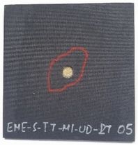
Additional test series of material M1 were impacted at 14 J and tested under RT and HW conditions. At this impact energy level, valid results were obtained when compression tests were performed: failure started at impact location and propagated along specimen width, as it can be observed in Figure 13. Similar failure modes were obtained for M2 specimens.
The results of these tests are shown in Table 9. Regarding material M2, as it was expected, a reduction in RT compressive residual strength was obtained when impact energy level is increased. Specifically, a decrease of 12% was produced when impact energy level was increased from 25 J to 35 J. Material M1 residual strength does not show a noticeable effect of ageing, while in the case of material M2, a remarkable decrease (21%) of compressive after impact strength under HW conditions was obtained when the specimens had been impacted at 25 J. The similarity between compression strength of RT and HW specimens of material M2 when they were impacted at 35 J may be due to the dispersion that is introduced by ageing process.
| Impact energy (J) | Residual compressive strength (MPa) | ||||
| RT | HW | ||||
| CV (%) | CV (%) | ||||
| M1 | 14 | 328 | 4 | 308 | 6 |
| M2 | 25 | 265 | 5 | 219 | 3 |
| 35 | 234 | 6 | 226 | 4 | |
3.5.2 Tension After Impact tests
Residual tensile strength of materials M1 and M4 (both EME and VEIL versions) are not comparable since impact boundary conditions were not exactly the same. Measured delaminated areas for M4-VEIL specimens (220±32 mm2) are similar to those obtained for M1 (222±35 mm2). On the other hand, delaminated areas of CNT-reinforced composite are smaller (173±34 mm2). The differences in damaged areas for M4-VEIL and M4-EME specimens are consistent with the residual tensile strength obtained (Table 10), which in average is higher for M4-EME material. Regarding material M2, the results of residual tensile strength is decreased 11% when impact energy is increased from 25 J to 35 J. This increase is similar to the one obtained for Compression After Impact tests, which is consistent since similar stacking sequences and impact boundary conditions were used. An example of failure mode is shown in Figure 13.
Effect of ageing is not noticeable. Although for most of test series tensile after impact strength slightly decreases when tests are conducted under HW conditions, there is not a clear trend and slight differences can be attributed to the dispersion of the results.
| Impact energy (J) | Residual tensile strength (MPa) | ||||
| RT | HW | ||||
| CV (%) | CV (%) | ||||
| M1* | 10 | 1700 | 4 | 1680 | 4 |
| M2 | 25 | 699 | 2 | - | - |
| 35 | 631 | 3 | - | - | |
| M4-EME | 10 | 1640 | 5 | 1620 | 3 |
| M4-EME-B2 | 10 | 1640 | 2 | 1690 | 2 |
| M4-VEIL | 10 | 1660 | 4 | 1490 | 2 |
| M4-VEIL-B2 | 10 | 1520 | 8 | 1460 | 3 |
4 Conclusions
In general, the material that exhibits best mechanical properties is M21/T800S (M1). This is a standard thermoset pre-preg material widely used for composite aerostructures.
For the assessed mechanical properties, the thermoset RTM material system has a worse behaviour than reference material M1. Nevertheless, material M2 offers key advantages regarding its manufacturing process. Liquid Resin Infusion allows to design complex geometric parts and produce unitized structures without the need of joints, which ultimately leads to a reduction in weight. It also eliminates the need of many post-manufacturing processes, which also contributes to cost reduction. Hence, as part of SHERLOC Project, this material has been selected to manufacture composite parts with complex shapes, such as the Aft pressure bulkhead joint, where manufacturing cost reduction compensates the extra material and increased weight is not significant.
Regarding the introduction of CNTs in the epoxy matrix (M4-EME), in general it does not have a positive effect on the mechanical behaviour. Although the differences are not excessively large, tensile and compressive properties of reference thermoset material (M1) are higher than the properties of its modified version M4-EME. Nevertheless, it has been found a positive effect regarding the delaminated areas of impacted specimens.
With respect to the insertion of damping veil (M4-VEIL), on the whole, it can be concluded that it worsens the mechanical behaviour of thermoset reference material (M1). Damping veil may create a discontinuity in the laminate which decreases its mechanical properties. Further and deeper research work should be performed in order to assess the effectiveness of damping veil.
The effect of ageing process depends on the examined material and assessed properties. In general, it has a greater impact on M4-EME and M4-VEIL materials. With respect to mechanical behaviour, it has been proved that ageing has more significant effect on strength properties, especially for matrix-dominated tests (UD laminates at 90º), as well as for In-Plane Shear tests, where both shear stress and modulus are affected.
The results obtained in this test campaign will be used to incorporate a knock-down factor in the design at detail and sub-component levels within SHERLOC Project.
Acknowledgments
The research leading to these results has gratefully received funding from the European JTI- CleanSky2 program under the Grant Agreement nº 314768 (SHERLOC). This project is coordinated by Imperial College London, and lead by Leonardo S.p.A, as Topic Manager.
References
[1] C. Soutis. Fibre reinforced composites in aircraft construction. Progress in Aerospace Sciences, 41, 143-151 (2005).
[2] http://sherloc-project.com/
[3] A. Mikhalchan, J. J. Vilatela. A perspective on high-performance CNT fibres for structural composites, Carbon, 150, 191-215 (2019).
[4] M. Jiménez, F. Simón, S. Goosens, B. De Pauw, T. Geernaert, F. Berghmans, D. Habas. Optical fibre based sensors application to structural health monitoring in composite materials. Materiales Compuestos. Vol. 2, Núm. 4 (2018).
[5] Dr. Chris Shennan. Nanomaterials in Advanced Composites. 2013, Hexcel.
[6] ASTM Standard D5229/D5229M – 14, “Standard Test Method for Moisture Absorption Properties and Equilibrium Conditioning of Polymer Matrix Composite Materials”, ASTM International, 2014, www.astm.org.
[7] ASTM Standard D3039/D3039M – 17, “Standard Test Method for Tensile Properties of Polymer Matrix Composite Materials”, ASTM International, 2017, www.astm.org.
[8] ASTM Standard D695 – 15, “Standard Test Method for Compressive Properties of Rigid Plastics”, ASTM International, 2015, www.astm.org.
[9] UNE-EN 2850:2017 – Aerospace series – Carbon fibre thermosetting resin – Unidirectional laminates – Compression test parallel to fibre direction (Endorsed by Asociación Española de Normalización in December of 2017).
[10] ASTM Standard D3518/D3518M – 18, “Standard Test Method for In-Plane Shear Response of Polymer Matrix Composite Materials by Tensile Test of a ±45° Laminate”, ASTM International, 2018, www.astm.org.
[11] ASTM Standard D7332/D7332M – 16, “Standard Test Method for Measuring the Fastener Pull-Through Resistance of a Fiber-Reinforced Polymer Matrix Composite”, ASTM International, 2016, www.astm.org.
[12] ASTM Standard D7136/D7136M – 15, “Standard Test Method for Measuring the Damage Resistance of a Fiber-Reinforced Polymer Matrix Composite to a Drop-Weigth Impact Event”, ASTM International, 2015, www.astm.org.
[13] ASTM Standard D7137/D713M – 17, “Standard Test Method for Compressive Residual Strength Properties of Damaged Polymer Matrix Composite Plates”, ASTM International, 2017, www.astm.org.
Document information
Published on 15/04/21
Accepted on 04/07/19
Submitted on 16/06/19
Volume 05 - Comunicaciones Matcomp19 (2021), Issue Núm. 2 - Caracterización analítica, numérica y experimental de los materiales compuestos. Materiales multifuncionales. Comportamiento de componentes estructurales., 2021
DOI: 10.23967/r.matcomp.2021.04.009
Licence: Other
Share this document
Keywords
claim authorship
Are you one of the authors of this document?

