1 Introduction
Delamination is one of the most common failure modes of composite materials. It may result from imperfections in the production process or may be caused by service life conditions, such as impact by foreign objects. The presence of delamination in the composite material may reduce the overall stiffness. From here the importance to fully characterize the interlaminar fracture toughness at high rate condition being the mechanical properties of the matrix resin highly strain rate dependent. Loading rates effects on composite materials has been a subject of investigation for some time [1-9]. Particularly on mode I and II interlaminar thoughness discrepancies in results are observed from the available reports in the rate effect on the initiation fracture toughness value in polymer composites. This contradiction in the available results is due to the different materials and experimental condition adopted by the autors. Some researchers reported that initiation fracture toughness increased with loading rate [4-6], while other studies contradict these findings [7-8]. Kusaka et al. [9] claimed a stepwise-drop of fracture toughness with increasing loading rate. On the other hand, a few researchers reported that dynamic initiation fracture toughness was insensitive to loading rate [10], and that the dynamic fracture toughness was insensitive to crack propagation speed [11]. It should be noted that most of these conclusions were based on test data that exhibited significant scatter and for different material systems. However, very few systematic studies have been carried out on the rate dependence of modes I and II interlaminar fracture behaviour from quasi-static to impact loading up to several tens of m·s-1, which will be necessary for the discussion of high-speed propagation of an unstable crack. This seems to be caused by the difficulty to estimate the fracture toughness under impact loading due to the influence of the inertia force both in the specimen and measurement system. Kusaka et a1. [1,2,9] have, therefore, spent much effort in developing experimental methods for estimating the fracture toughness under impact loading demonstrating that fracture toughness decreased stepwise with increasing loading rate only in the region between 0.05 mm/min and 5 mm/min and was rate-insensitive above this speed range.
The purpose of this work is to characterize the rate dependence of mode I interlaminar fracture behaviour in two unidirectional UD and one plain woven carbon-fibre/epoxy composite laminates over a wide range of loading rates from quasistatic (displacement rate =0.5-450 mm/min) to high rate ( =100-2000 mm/s). The experimental technique proposed by Kusaka et al. [1,2,9] was employed to provide accurate measurement of the fracture toughness under high rate.
2 Experimental procedure
2.1 Materials and specimen preparation
Two unidirectional UD carbon fiber reinforced polymer laminates were studied in this work sharing the same type of carbon fiber IM7 (Hexcel HexTow) and two different epoxy resins, namely, Hexcel 8552 and M91. Both materials exhibited different behavior under dynamic and impact loading. The unidirectional panels of 12 plies, with a lay-up of [0]6s, were cured in the autoclave according to the prepreg manufacturer’s recommended curing cycle (180 °C for 135 min, with a heating/cooling rate of 2 °C/min). The cured thickness of the panel was 3 mm. A 25 µm thick polytetrafluoroethylene (PTFE) film was inserted between the plies at the mid-plane of the panel to introduce an artificial starter slit. A pre-crack of about 2-3 mm was first introduced with a razor blade for the WIF test, meanwhile for the DCB the sample was pre-cracked loading and opening a few millimeters in order to reduce the effect of the resin rich region at the film’s tip.
2.2 Methodology for quasi static DCB and impact WIF test
The DCB method [12-13] which is commonly used to estimate the mode I interlaminar fracture toughness of composite laminates, was employed for quasi-static fracture tests. Figure 1 shows the geometry of a DCB specimen, where P is the load applied to the specimen and is the displacement of the loading point. In these specimens, the width is =25 mm, thickness =3 mm and the initial crack length was set to = 25 mm. The displacement rates used in the quasi-static tests were = 0.5-500 mm/min.
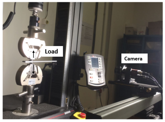
DCB tests were carried out under constant cross-head speeds with a screw-driven testing machine Instron 5966, Figure 2.
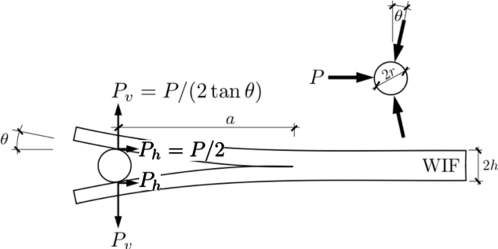
For the dynamic loading conditions, the WIF (wedge-insert-fracture) method was applied to avoid any possible asymmetry during dynamic loading in stantadard DCB specimens. The WIF method was used to characterize dynamic fracture assuming displacement rates in the range of = 100-2000 mm/s. Figure 3 shows the geometry of a WIF specimen, where and are the transferred force components of the load induced by the actuator .
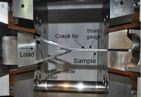
WIF tests were carried out with a Gleeble 3800-GTC system from which the load, , and the displacement, , under impact loading are measured using specimens shown in Figure 4.
In the case of WIF specimens, two strain gages of 350±0.3%Ω were attached to the bending surface of the WIF specimen respectively at 15 and 30 mm from the initial crack tip area. A Data Acquisition (DAC) System QuantumX MA-840A, was used for the data recording from the strain gauge with a data acquisition rate of 19.2 kHz. The strain monitored was used to estimate the opening force and, thus, to estimate the critical energy release rate, . It was assumed that the compressive strain peak measured monitor the crack initiation process in the velocity tests. To avoid parasitic oscillations of the signals, a thin (1.5 mm) sheet of rubber nitrile was utilised for damping the rising of the incident stress wave and then suppressing the vibration of the specimen.
In order to achieve a better understanding of the fracture mechanisms during the crack growth, scanning electron microscopic fractographies of the delaminated surfaces have been taken. The microscopic fractographies have been performed with a with EVO MA15, Zeiss, in low vacuum mode with a 15 kV potential and a vacuum pressure between 10 and 15 Pa.
2.3 Estimation of energy release rate
Assuming the postulates of linear elastic fracture mechanics (LEFM), the energy release rate can be obtained from the variations of the elastic energy of the system when a crack extension Δa is produced. For bidimensional solids of width , the energy release rate can be expressed as
|
|
(1) |
where stands for the specimen compliance for a given crack length and is the load at the onset of fracture. The compliance at the loading point is given by the following relation Eq.2 [13]:
|
|
(2) |
where and can be determined experimentally from the DCB specimens by measuring the relation between the compliance and the crack length [13]. The basic fitting results are summarized in Table The obtained relationship was fitted according to equation (2) yielding the values shown in Table 1. Quasi-static tests carried out on longitudinal and transverse tensile coupons revealed no significant strain rate dependence in this regime so it was assumed that the calibration compliance was independent of the loading rate according to the bulk arm behavior.
| Material | (N1/3mm-2/3) | β |
| 8552/IM7 | 11.42 | 0.51 |
| M91/IM7
|
11.69
|
-0.197 |
Substituting Eq. 2 to Eq. 1, the energy release rate, , can be finally obtained by using following equation for DCB specimens:
|
|
(3) |
For the dynamic test, we assumed that the relation between the strain gauge reading in WIF specimens, loaded under quasi-static conditions by the DCB method, can be used to estimate the dynamic fracture toughness as
|
|
(4) |
where is the moment of inertia of the arm and its elastic modulus in the fiber direction. The relation between the applied load and the deformation of the strain gauge is given by the indirect compliance term (note that the strain is compressive) as
|
|
(5) |
This term can be calibrated experimentally by loading some DCB specimens instrumented with a strain gauge at the crack tip and/or determined from finite element modelling.
Finally, considering the insert contact angle (see Figure 3) to be small, the ratio of is equivalent to the compliance of a DCB specimen. Substituting Eq. 5 into Eq.3, the estimation of the energy release rate, for the WIF specimen is:
|
|
(6) |
In this work, the dynamic value of , was determined using the maximum strain in compression of the time history of the gauges attached to the specimen to determine the opening force .
3 Results and discussion
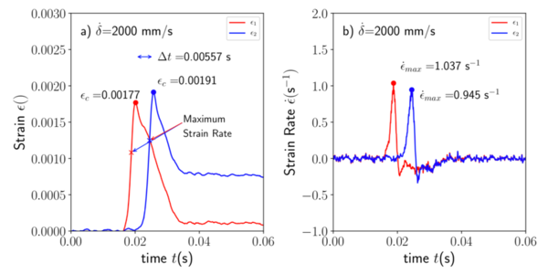
A typical plot containing the strain gauge readings, and , installed in the WIF specimen is presented in Figure 5a) for the IM7/8552 material loaded at =2000 mm/s. The signal of the strain gauges was first smoothed using a Savitzky-Golay filter in order to obtain a more precise time-derivative for the subsequent strain-rate determination, Figure 5b). The strain raised suddenly as a consequence of the dynamic loading reaching a peak which was attributed to the pass of the moving crack front through the section where the strain gauges were installed. The crack velocity obtained from the temporal distance between the strain gauge peaks, see in Figure 5a), from each gauge corresponded roughly with the velocity of the displacement pin . The discrepancies could be attributed to errors in the distance between strain gauges during the attachment process.
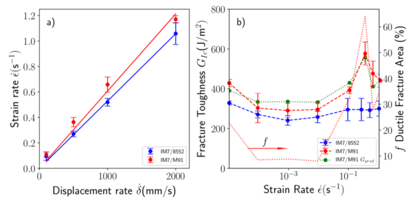
Figure 6a) shows the relationship between the applied displacement rate and the corresponding strain rate of the loading arm measured using the WIF specimens. The results showed a linear dependence on the displacement rate. Once the strain rate and the maximum peak is determined for each of the testing conditions, the interlaminar fracture toughness can be determined for both type of materials, Figure 6b).
As in the quasi-static test, IM7/M91 was tougher than IM7/8552 so, for the same nominal geometry, the corresponding critical strain at the onset of crack propagation is considerably higher. The interlaminar fracture toughness of the IM7/8552 material followed the same trends observed in the quasi-static tests with average values in the order of 300J/m2.
However, IM7/M91 toughness presented a continuous increase up to the maximum value of 577±50J/m2 for =500 mm/s which is almost the double than under quasi-static conditions. This increase in the interlaminar toughness of the IM7/M91 was not detected in the IM7/8552 one. Remarkably, the peak of toughness observed for IM7/M91 laminates did not occur for the maximum displacement rate but an intermediate one. Even in this case, the toughness obtained for =2000mm/s was 440±33J/m2 which is~50% higher than the quasi-static value.
3.1 Fracture mechanisms
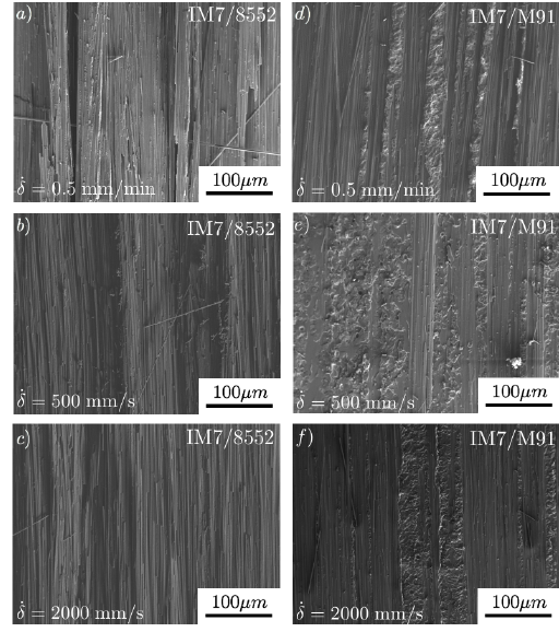
The fracture surfaces of the tested DCB and WIF specimens were first visualized using the scanning electron microscope. The results were gathered in Figure 7 for both materials, and three displacement rates of = 0,5; 500 and 2000 mm/s. In the case of the IM7/8552 material, the fracture surface was totally flat irrespective to the displacement rate with some evidences of fiber/matrix interface fracture and fiber bridging. However, the appearance of the fracture surfaces of the IM7/M91 laminates were totally different. In this case, the fracture surface included some strips following the fiber direction containing evidence of ductile fracture propagating through the interleave material while the remaining surfaces were very similar to those observed in the IM7/8552. The most plausible fracture mechanism could be attributed to crack migration from the interleaved region into the fiber ply.
4 Conclusions
DCB and WIF specimens of IM7/8552 and IM7/M91 composite panels were prepared for characterization of the mode I fracture toughness under dynamic conditions. Quasi-static loading conditions were also imposed in DCB specimens using an electromechanical testing frame using arm loading speeds ranging from 0.5 to 450 mm/min. In the case of dynamic loading, a Gleeble 3800-GTC thermal-mechanical system was used instead which allowed to impose loading speeds between = 100 to 2000 mm/s. DCB tests were used to characterize the fracture toughness for quasi-static conditions as well as the calibration curve for the specimen compliance required for the data reduction method used. WIF specimens were instrumented with two strain gauges installed far from the crack tip. The evolution of the strain was captured and the maximum value in compression was used to infer the corresponding toughness under dynamic conditions. In addition, the maximum strain rate determined from the gauge signals was used to compare WIF and DCB tests under the same conditions (same abscissa axis). The results revealed no rate dependence behavior in mode I for the IM7/8552 while the IM7/M91 showed higher values at high rate with a maximum peak at 500 mm/s. The fracture surface of IM7/M91 laminates exhibited different regions corresponding to the ductile tearing of the interleaved region probably triggered by particle debonding while in the remaining surface fiber bridging and breakage were evident.
Acknowledgements
The research leading to these results has received funding from the European Union as Horizon 2020 research and innovation program under the Marie Sklodowska-Curie grant agreement No 722096, DYNACOMP project.
References
[1] Kurokawa, T., Kusaka, T., Shimazaki, T., Yamauchi, Y. and Kawashima, T., Dynamic interlaminar fracture toughness of cfrp composite laminates. Proceedings of IUTAM Symposium, (1995) 2 17-224
[2] Kusaka, T., Kurokawa, T., Hojo, M. and Ochiai, S., Evaluation of mode II interlaminar fracture toughness of composite laminates under impact loading, Key Eng. Mater.,141-143 (1998) 477-497.
[3] Kageyama, K., Kobayashi, T. and Chou, I.-W., Analytical compliance method for mode I interlaminar fracture toughness testing of composites. Composites, 1987, 18, 393-399.
[4] Aliyu AA, Daniel IM. Effects of strain rate on delamination fracture toughness of graphite/epoxy In: Johnson WS, editor. Delamination and debonding of materials. ASTM STP 876; 1985. p. 336–48.
[5] Yaniv G, Daniel IM. Height-tapered double cantilever beam specimen for study of rate effects on fracture toughness of composites. In: Whitcomb JD, editor. Composite materials testing and design eighth conference. ASTM STP 972; 1988. p. 241–58.
[6] Smiley AJ, Pipes RB. Rate effects on mode I interlaminar fracture toughness in composite materials. J Compos Mater 1987;21: 670–87.
[7] Daniel IM, Shareef I, Aliyu AA. Rate effects on delamination fracture toughness of a toughened graphite/epoxy. In: Johnston NJ, editor. Toughened composites. ASTM STP 937; 1987. p. 260–74.
[8] Daniel IM, Yaniv G, Auser JW. In: Marshall IH, editor. Rate effects on delamination fracture toughness of graphite/epoxy composites. In: Proceedings of fourth International Conference on Composite Structures, Amsterdam: Elsevier; 1987. p. 2.2258–72.
[9] Kusaka T, Hojo M, Mai Y-W, Kurokawa T, Jojima T, Ochiai S. Rate dependence of mode I fracture behavior in carbon fiber/epoxy laminates. Compos Sci Technol 1998;59:591–602.
[10] Blackman BRK, Dear JP, Kinloch AJ, MacGillivray H, Wang Y, Williams JG, Yayla Y. The failure of fiber composites and adhesively bonded fiber composites under high rates of test: mode I loading experimental studies. J Mater Sci 1987;30:5885–900.
[11] Guo C, Sun CT. Dynamic mode I crack propagation in a carbon/epoxy composite. Compos Sci Technol 1998;58(9):1405–10
[12] Whitney, J. M., Browning, C. E. and Hoogsteden, W., A double cantilever beam test for characterizing mode I delamination of composite materials. J. Reinforced Plastics and Composites, 1982, 1, 297-313.
[13] Hojo, M., Kageyama, K. and Tanaka, K., Prestandardization study on mode I interlaminar fracture toughness test for CFRP in Japan. Composites, 1995, 26, 243-255.
Document information
Published on 17/01/21
Accepted on 04/07/19
Submitted on 02/06/19
Volume 05 - Comunicaciones Matcomp19 (2021), Issue Núm. 1 - Comportamiento en servicio – Inspección y reparación., 2021
DOI: 10.23967/r.matcomp.2021.01.007
Licence: Other
Share this document
Keywords
claim authorship
Are you one of the authors of this document?


