- Correction added on 24 November 2015, after first online publication: This article has been edited for language since initial online publication on 12 November 2015.
Abstract
Detail analysis of microcontroller (μC)-based smart dual-axis automatic solar tracking system utilizable for different purpose is presented in this paper. Working of the proposed smart tracking system is based on the automatic rotation of photovoltaic (PV) panel depending on the intensity of sun light. It will help in maintaining the alignment of PV panels with the Sunlight to obtain maximum solar power at any instance. Intensity of sunlight on a particular alignment of solar PV panel varies throughout the day. As the intensity of light on PV panel decreases the proposed smart tracking system has the intelligence to automatically redirect the panel alignment to get maximum intensity of light. Four Light Dependent Resistor (LDR) sensors are placed on the surface of the PV panel to detect the intensity of light. Two servomotors are employed in the back side of PV panel system to align the panel with maximum luminous intensity. Design and construction of the proposed tracking system is presented to measure the efficiency over the fixed PV panel. Experimental results indicate that the power output of the PV system, using the proposed tracking system is increased up to 19.73% compare to the traditional fixed PV panel. The efficiency of the proposed design is considerably higher and comparable to the existing design which has the average efficiency around 12–15%.
Introduction
Solar Photovoltaic (PV) energy is one of the most popular, noiseless renewable energy with production of lesser pollutants which degrades the environment [1-3]. Output of the solar PV system is dependent on the outdoor filed condition in which it is operating. The major factor that affects the output of the PV panel is the movement of the Sun in the Sky over the day. To maximize the power output from PV panel, the panel should be aligned with the Sun [4].The efficiency of a PV system increases through maximizing the power output from the PV panel. The efficiency of PV panels are increased, using solar trackers which are the most precise and proven technology till date. Recently solar trackers have become a popular solution to increase the efficient usability of solar energy worldwide [5, 6]. Except the cost of PV technology, solar PV energy is enormously available and completely free of cost. PV systems are becoming popular in the field of modern electric power applications. Photovoltaic devices are nothing but a semiconductor which can convert sunlight directly into electricity with lower maintenance costs. It is clear from previous literature that the development of the smart solar tracker system maximizes the energy generation from the PV module. In traditional fixed PV panels, the tilt angle is location depended and varies depending on whether a slight winter or summer bias is preferred in the system. The PV panel should face the equator plane with the tracking of the Sun position to maximize the energy generation from PV panel. The maximum energy generation through solar tracking is possible when the tilt angle of the PV panel is matched with the seasonal variation of the suns altitude. Solar movement models were used to determine the azimuth and the elevation angles of the Sun while control algorithms including date, time, and geographical information of the installation site were executed in a μC [7, 8].
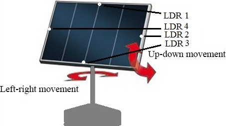
The paper is aimed to design the smart dual axis sun tracking solar PV system which follows the Sun path independent of motor speed. PV panels produce electricity directly from the Sun, so it is a viable source of electricity in remote areas where grid connectivity is unavailable. The output of the PV panel is dependent on the intensity of sunlight and the angle of incidence radiation. This paper represents a smart dual-axis Automatic Solar Tracking System with high efficiency. The proposed tracker is completely automatic and keeps the PV panel in the face of the Sun until the sunlight is ample to produce electricity. The proposed tracker considers the Sun as the guiding source. To rotate the PV panel toward the direction where the intensity of sunlight is maximum, LDRs constantly monitor the sunlight. Movement of the PV panels is controlled by the microcontroller-based control panel [9-16]. The proposed smart dual axis tracker is shown in Figure 1.
|
|
|
Figure 1. Schematic diagram of smart dual-axis Tracker. |
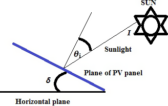
Perpendicular to the PV panels exposed face is the normal to the cell. The striking angle of sunlight is shown in Figure 2. The angle between the incident sunlight to the normal is the angle of incidence (θi). Assuming the sunlight I Watt/m2 incident on a solar cell, the available sunlight to the solar cell for power generation (W) can be calculated as:
|
|
|
Figure 2. Angle of sunlight to the plane of photovoltaic panel. |
|
|
(1) |
where, A is the area of PV panel.
Considering the linear relationship between light intensity and the produced voltage, the microcontroller can produce the resolution in angle (θR),
|
|
(2) |
where,
VR: Resolution voltage produced by the microcontroller.
VOC: Open circuit voltage of the PV panel.
The angle between the backs of the panels and horizontal plane is δ. So the angle between the normal to the faces of the panels is 180°-δ indicated as β. α is the angle of the sun to some reference point. Incorporating the angular position of the tracker (θt) according to the same reference point as the Sun, the voltage across PV panel is presented in equation (3).
|
|
(3) |
Considering the earth rotation of full 360° in 24 h in an east-to-west direction, the angle of the Sun to the zenith on the earth known as the X-direction is calculated in equation (4).
|
|
(4) |
To find an equation for the Sun movement in the Y-direction that is in the north-south direction, the 23.45° tilt of the earths axis to its orbit around the sun is considered. So, as the earth rotates around the sun, the equators Y angle to the sun goes from 0° at the vernal equinox to 23.45° at the summer solstice and back to 0° at the autumnal equinox. Then to −23.45° at the winter solstice and finally back to 0° at the vernal equinox again. This angle varies over the 8760 h; the angle to the zenith on the equator (ZYE) is given as:
|
|
(5) |
where, Tm: Hours from the midnight on the vernal equinox.
The latitude comes into effect as the point chosen might not be at the equator. So considering the latitude (φ) in equation (5) the angle of the sun to the equator is given by equation (6).
|
|
(6) |
Using equations (4) and (6), the amount of available radiation to a particular point can be calculated. On perfectly sunny and clear conditions, the amount of radiation is a function of the cosine of the angle of the Sun to the zenith. So the radiation coming from both individual directions is presented in equations (7) and (8).
|
|
(7) |
|
|
(8) |
Now the total radiation of the Sun striking a point on the earths surface at latitude φ at time Tm hours from midnight on the vernal equinox is
|
|
(9) |
System Configuration
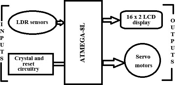
Solar trackers are for accurate determination of the position of the Sun. This approach enables the PV panels to obtain the maximum solar radiation. As the specialty of the system is smart control, using embedded software, so the microcontroller is the brain of the entire system. The function of the proposed smart tracker is based on the program in Arduino flashed in the μC ATMEGA-8L. The microcontroller (μC) ATMEGA-8L is able to convert the analog PV cell voltage in the digital values and also provides two output channels to control the rotation of servomotor. The design of the proposed system is divided into two parts- hardware and software programming. Block diagram of μC and associated circuitry is shown in Figure 3.
|
|
|
Figure 3. Block diagram of microcontroller and associated circuitry. |
Hardware system
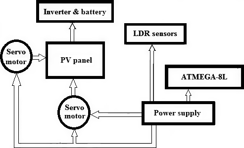
The proposed tracking system consists of six PV Modules, battery, four LDR sensors, the voltage regulator, μC-ATMEGA8L, and the 8 MHz crystal oscillator. LDR sensors sense the sunlight intensity and provide feedback to μC-ATMEGA8L. The μC processes the sensor input and provides two PWM signals for the movement of servomotors. An 8 MHz crystal oscillator was used to provide the necessary clock input. The total system configuration is shown in Figure 4.
|
|
|
Figure 4. Configuration of the proposed smart dual-axis automatic solar tracking system. |
PV panel
PV panels directly convert the solar energy into electrical energy. Six PV panels bought from the same reputed company which is capable of generating 250 WP power each. The setup with the series connected to six PV panels is installed for the experiment, that is, the total capacity of the system is 1.5 kWP.
Power supply of ATMEGA8L
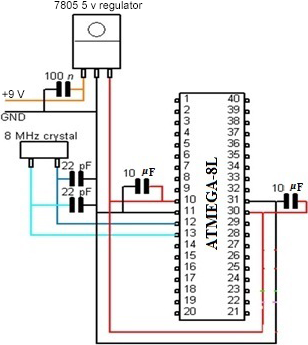
The input voltage 9V DC is injected into the PCB after the necessary stepping down from the adapter. This 9V DC supply goes to 7805 Voltage Regulator from where the output 5V DC spreads to all logic circuitry. Figure 5, shows the circuit of power supply of the ATMEGA8L.
|
|
|
Figure 5. Circuit diagram of power supply. |
Light-dependent resistors model
To capture maximum light energy four light dependent resistors (LDR) are used in the proposed system. LDR is a resistor which shows negative temperature gradient or photoconductivity. The resistance of an LDR is extremely high. When illuminated the light resistances will drop dramatically [17] and the main controller receives an analog input from the LDR.
The internal Analog-to-Digital converter (ADC) compares the solar panel sensor voltage. The analog input from the light sensor goes into the ADC port of the μC and the digital signal is displayed in the LCD display.
LCD display
Liquid crystal display screen is an electronic display module for a wide range of applications. A 16 × 2 LCD display is commonly used in various devices and circuits. These modules are preferred over seven segments and other multisegment LEDs. LCDs are becoming popular nowadays as it is cost-effective, easily programmable, and have no limitation of displaying special and even custom characters unlike in seven segments.
Motors
Two servomotors are used to move the solar panel at the maximum light source location sensed by the LDR. In order to accurately hold a position servomotors need a pulse every 20 ms. The microcontroller gives two different PWM signals for the movement of the solar panel through the servomotor.
The internal 512 Kb EEPROM is used to maintain the compiled memory of μC after the power goes out. The microcontroller ATMEGA8L is compiled with the help of the Arduino. Arduino is an open-source electronics prototyping platform based on flexible, easy-to-use hardware, and software.
Software operation
The programming language was utilized for the proposed tracking system to assure design objectives, while enriching the level of understanding. In the proposed tracking system, the software operation is separated into two parts. The first one is the initial positioning prior to powering up the system, that is, the photocell must be manually set to a zero point.
The second part is the tracking of the sunlight which is the brain of the program. When the tracker has set its primary position to sunlight, it is ready to align itself more preciously and continue tracking the light. The total software operation is compiled in Arduino. This compiled program controls the total hardware operation, including the function of the tracker and the servomotor will rotate according to the instruction of this program.
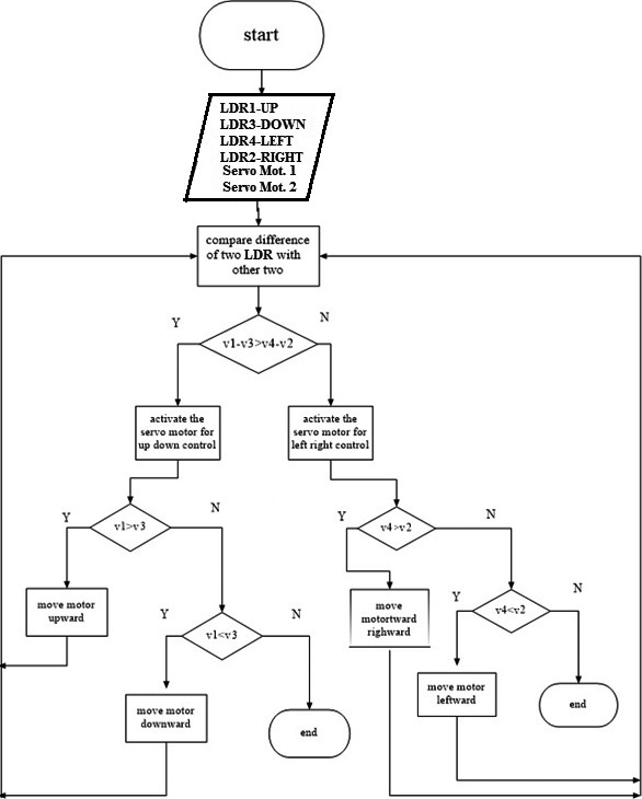
The flowchart of the software procedure is presented in Figure 6.
|
|
|
Figure 6. The flow of the software procedure. |
Results and Discussion
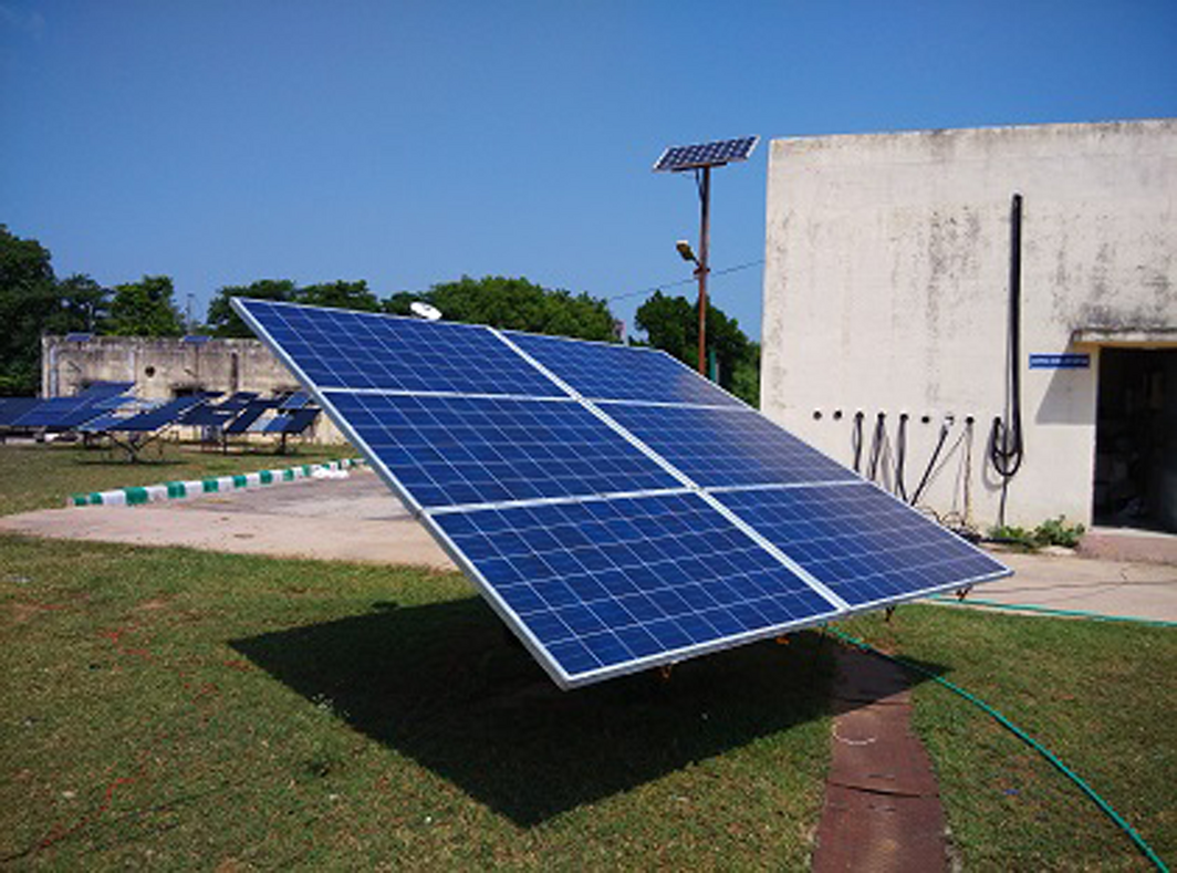
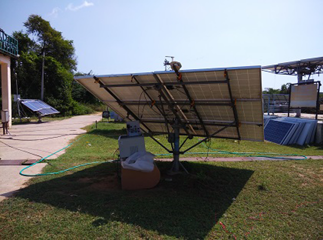
The experimental results of the fixed PV panel and PV panel with the proposed intelligent solar tracker system are compared to know the acceptability of the proposed model. In the experimental setup of the proposed intelligent tracking system, six PV panels each of 250 WP capacity from the same manufacturer, the solar panel installation stand, the pyranometer, and two servomotors are used as shown in Figure 7 and Figure 8. Six PV panels are connected in series in this experiment. The experiment was performed at the National Institute of Solar Energy (NISE), India an autonomous body for solar energy research. NISE has almost all the solar energy-related laboratory facilities accredited by NABL. The required data are collected through performing simple experiment. The open-circuit voltage are recorded using a practical display (LCD) connected to the system. A clear sunny day on 10th of September, 2015 was selected for performing the experiment. The average temperature recorded was around 35°C. At first, the system started scanning the angle in which the solar intensity is maximum and aligned it with the maximum solar intensity position. Due to very low motor speed, motor speed parameter can be neglected and the system only focused on tracking of sun intensity.
|
|
|
Figure 7. Front side of experimental set up with smart tracking system. |
|
|
|
Figure 8. Back side of experimental set up with smart tracking system. |
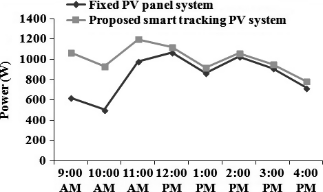
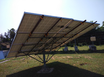
The experiment results of the traditional fixed PV system and the proposed dual- axis smart tracking PV system are shown in Tables 1 and 2 and Figure 9. Figure 10 shows the back side of fixed PV panel system. The proposed smart solar tracker is able to follow the sun angle. The smart solar tracker produces a higher power output as compared to the static PV panel system.
| Parameter | Value |
|---|---|
| Cell type | Multi crystalline silicon |
| Maximum power (Pmax) | 250 watt |
| Voltage at Pmax | 30.5 V |
| Current at Pmax | 8.2 A |
| Short-circuit current (Isc) | 8.6 A |
| Open-circuit voltage (Voc) | 36.0 V |
| Time of day | 9:00 am | 10:00 am | 11:00 am | 12:00 pm | 1:00 pm | 2:00 pm | 3:00 pm | 4:00 pm |
|---|---|---|---|---|---|---|---|---|
| Fixed axis solar panel | ||||||||
| Voltage, V1 (volt) | 84.18 | 69.54 | 139.08 | 151.16 | 128.83 | 152.99 | 142.37 | 115.29 |
| Current, I1 (A) | 7.38 | 7.22 | 7.05 | 7.05 | 6.72 | 6.72 | 6.40 | 6.23 |
| Power, P1 (watt) | 621.25 | 502.08 | 980.51 | 1065.68 | 865.74 | 1028.09 | 911.17 | 718.26 |
| Dual axis solar panel | ||||||||
| Voltage, V2 (volt) | 135.42 | 120.78 | 158.48 | 155.18 | 129.93 | 153.72 | 144.57 | 122.24 |
| Current, I2 (A) | 7.87 | 7.71 | 7.54 | 7.22 | 7.05 | 6.89 | 6.56 | 6.40 |
| Power, P2 (Watt) | 1065.76 | 931.21 | 1194.94 | 1120.4 | 916.00 | 1059.13 | 948.38 | 782.34 |
| % increase in efficiency | 71.15 | 84.52 | 22.09 | 5.06 | 6.25 | 2.92 | 3.95 | 8.33 |
|
|
|
Figure 9. Fixed and dual axis panel power comparison. |
|
|
|
Figure 10. Back side of fixed photovoltaic panel system. |
The output power of the smart tracker-based PV system was compared with the fixed PV panel design to determine the acceptance of the proposed smart solar tracker system. As expected, the overall efficiency generated by the proposed smart tracking PV system is higher than that of static PV system.
The efficiency and the average increase in efficiency in power of the proposed smart tracker model compared to that of the fixed axis system is calculated using equations (10) and (11), respectively.
|
|
(10) |
|
|
(11) |
From the experimental results, it is observed that the generation of the PV system, using the proposed smart tracker is increased up to 19.73% compared to the traditional fixed PV panel system. The average efficiency of solar trackers [18] is around 12–15% and hence, the proposed design is slightly higher and comparable to the existing design. The experimental data shows that at present a PV system is competitive where small amounts of energy are required and places which are far away from an electric grid or any other source of energy.
Conclusion
This paper presents the design and testing of a smart dual-axis solar tracker. The proposed smart solar tracking model is developed, using microcontroller ATMEGA-8L. Based on the results obtained, it can be concluded that the system will react at its best because a maximum voltage is produced as compared with a traditional fixed system. Experimental results indicate that the generation of the PV system, using the proposed smart tracker is increased up to 19.73% compared to the traditional fixed PV panel system. In order to get the maximum output regardless of motor speed, the system is able to track and follow the intensity of the Sun. Besides, the low speed servomotor has been used for neglecting motor speed parameters and therefore the system only focuses on the tracking of Sun intensity. For the cost and benefit of the proposed solar tracker system, it has some special features such as the initial expenditure on the equipment is usually high but there is no fuel cost involved and the maintenance cost is low. So, economically and environmentally this intelligent smart dual axis solar tracking system development will be a technique to use solar-energy more widely and wisely.
Conflict of Interest
None declared.
References
- Berberi, P., S. Thodhorjani, P. Hoxha, and V. Muda. 2013. Photovoltaics: between a bright outlook and uncertainty. Energy Sci. Eng.1:72–80.
- Chakraborty, S., P. K. Sadhu, and N. Pal. 2015. Technical mapping of solar PV for ISM-an approach toward green campus. Energy Sci. Eng.3:196–206. doi:10.1002/ese3.65.
- Pagliaro, M., F. Meneguzzo, F. Zabini, and R. Ciriminna. 2014. Assessment of the minimum value of photovoltaic electricity in Italy. Energy Sci. Eng.2:94–105.
- Syed, A.2013. Sun tracking system with microcontroller 8051. Int. J. Sci. Eng. Res.4:2998–3001.
- Lo, S., F. Cheng, V. Chang, W. D.-J. Liu, L. Chang, O. F. Adurodija, et al. 2015. Design, operation, and performance evaluation of a cable-drawn dual-axis solar tracker compared to a fixed-tilted system. Energy Sci. Eng. doi:10.1002/ese3.92.
- Panait, M. A., and T. Tudorache. 2008. A simple neural network solar tracker for optimizing conversion efficiency in off-grid solar generator. Int. Conf. Renew. Energy Power Quality, 278:1–5.
- Sadhu, M., S. Chakraborty, N. Das, and P. Sadhu. 2015. Role of solar power in sustainable development of India. TELKOMNIKA Indones. J. Electr. Eng.14:34–41. doi:10.11591/telkomnika.v14i1.7668.
- Chin, C. S., A. Babu, and W. McBride. 2011. Design, modeling and testing of a standalone single axis active solar tracker using MATLAB/Simulink. Renewable Energy36:3075–3090.
- Enrique, J. M., E. Duran, M. Sidrach-de-Cardona, and J. M. Andu. 2007. Theoretical assessment of the maximum power point tracking efficiency of photovoltaic facilities. Sol. Energy81:31–38.
- Yiwang, W., and S. Jia. 2012. Design of a digital solar panel automatic tracking controller for photovoltaic generation system. Power Energy Eng. Conf.Shanghai (Asia-Pacific):1–4.
- Feng-Ran, L., X. Li, and L. Wen-Jia. 2011. The design of automatic tracking system for solar cell. Artif. Intell. Manage. Sci. Electr. Commer.Deng Leng (2nd International Conference on):4451–4454.
- Md. Ismail, H., A. K. Shakil, and M. Shafiullah. Power maximization of a photovoltaic system using automatic solar panel tracking along with boost converter and charge controller. 7th International Conference on Electrical and Computer Engineering, 20-22 December, 2012, Dhaka, Bangladesh.
- Zhang, B., G. Gao, and Y. Zhu. 2010. Designment of automatic tracking system of solar energy system. 2nd International Conference on Industrial Mechatronics and Automation.
- Asmarashid, P., H. Ammar, and A. M. Handy. A design of single axis sun tracking system, the 5th international power engineering and optimization conference (PEOCO2011), Shah Alam, Selangor, Malaysia: 6–7 June 2011
- Tetsumi, H., and T. Takahiro. 2001. A proposal of efficiency improvement with solar power generation system, IECON'O1: the 27th Annual Conference of the IEEE Industrial Electronics Society.
- Das, S., P. Sadhu, N. Pal, and S. Mukherjee. 2014. Single Axis Automatic Solar Tracking System Using Microcontroller. TELKOMNIKA Indones. J. Electr. Eng.12:8028–8032.
- Zolkapli, M., S. A. M. AI-Junid, Z. Othman, A. Manut, and M. A. Mohd Zulkifli. High-efficiency dual-axis solar tracking developement using Arduino, 2013 International Conference on Technology, Informatics, Management, Engineering & Environment, Bandung, Indonesia, June 23–26, 2013.
- Mousazadeh, H., A. Keyhani, A. Javadi, H. Mobli, K. Abrinia, and A. Sharifi. 2009. A review of principle and sun-tracking methods for maximizing solar systems output. Renew. Sustain. Energy Rev.13:1800–1818.
Document information
Published on 01/06/17
Submitted on 01/06/17
Licence: Other
Share this document
Keywords
claim authorship
Are you one of the authors of this document?
