1 Introduction
It is essential to understand the cause of void formation in order to lower voids content in Liquid Moulding Manufacturing (LCM). Voids can be originated from the volatilization of dissolved gases in the fluid or also from initial air bubbles content in the resin [1]. Nevertheless, the major responsible effect for void generation is the mechanical entrapment of air caused by the different paths where resin flows through the preform. The non-homogeneous spatial distribution of the fabric produces the existence of two different flows mechanisms at the mesoscopic level. Firstly, in regions with high permeability, the space between fibre bundles, the viscous forces dominate, while, secondly, inside the fibre bundles capillary forces prevail. This competition between viscous and capillary forces is the main explanation of air entrapment in LCM. Experimental results have led to conclude that this competition between viscous and capillary forces can be described by the non-dimensional modified capillary number defined as Ca*[2,3,4]
|
|
(1) |
where μ stands for viscosity, v is the resin average velocity, γ is the surface tension and θ refers to the contact angle between resin and fibre. Patel et al. [5] and Rohatgi et al. [6] showed experimental evidence of the existence of a single master curve of void content plotted as a function of the modified capillary number. These authors also reported that below a certain value of the capillary number, Ca*<10-3, capillary forces domain the flow over the viscous forces, Figure 1a). As explained above, macropores are then generated in the space between fibre bundles under these conditions. On the other hand, microvoids are generated inside the fibre tows when viscous forces domain the flow, Ca*>10-2, as it can be seen in
Figure 1c). Optimizing this two flows (intratow and intertow) will result in components with reduced void content which is produced in the range of 10-3<Ca*<10-2 as it is shown in Figure 1b).
The effect of surface tension in the capillary forces are often neglected in many process, for example in LCM at the microscopic scale. However, the prominence of capillary forces in the flow process at the microscale is the cause for creating some of the voids in the material. Therefore, several authors started to work in this topic in the field of composites [7,8,9] and is one of the main goals for this work. Here, we will focus on understanding the fundaments of the physics of infiltration at the microlevel using advanced characterization techniques based on X-ray tomography through the spontaneous and forced impregnation of individual dry fiber bundles.
2 Methodology
2.1 Materials and experimental techniques
Two epoxy resins and corn syrup resin blends (70% corn and 30% water) were used in the experiments. D.E.R. ™ 736 (a Polymer of epichlorohydrin-polyglycol) is an epoxy resin with a very low viscosity. It can be easily blended with D.E.R. ™ 332 (a high viscosity and high purity bisphenol A diglycidylether) in order to obtain a target viscosity. Up onwards, ResinL refers to a blend of D.E.R. ™ 736 (50%) and D.E.R. ™ 332 (50%) by weight, in other words, a low viscosity resin while ResinH to pure D.E.R. ™ 332, a high viscosity resin. Besides, as explained above, it may be required to incorporate to the fluid some agents to enhance X-ray contrast.
Epoxy resins are not aqueous solutions and therefore salts are not soluble into them. So, in this case, an organic compound with a high composition of bromine was used. Due to the great ease to dissolve it into epoxy resins, 4-Bromophenol (BrC6H4OH) was added. This substance creates a higher contrast between fibres and fluid. A 10% by weight of the dopant is added to the blend. In these case, ResinLB and ResinHB refer to the doped with 4-Bromophenol versions of the previous ResinL and ResinH described.
E-glass tows containing around 2000 filaments were extracted from a plain-woven fabric. Each single glass fibre has a diameter in the range of 16±2 μm. Depending on the supplier, fibres are coated with a material called sizing used to improve wetting of fibres during impregnation. The interaction with the fluid by means of the contact angle is, therefore, dependent on the properties of the sizing used during fiber and fabric manufacturing and the environmental conditions.
2.2 Properties of the fluids
A rotational viscometer Fungilab Alpha L with resolution of 0.1 mPas was used in the experiments to measure the fluid viscosity μ. The results are presented in Table 1. The viscosity is slightly modified by the presence of the dopants for visualization enhancement.
| Liquid | μ (mPas) | μ (mN m-1) |
| Corn syrup (70-30) | 157 | 60±0.5 |
| ResinL | 204 | 48±0.2 |
| ResinLB | 289 | 48±0.2 |
| ResinH | 2805 | 61±0.5 |
| ResinHB | 1639 | 56±0.2 |
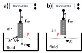
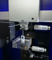
The surface tension was measured using a modified Wilhelmy test. To this end, a dry filter paper 1x2mm2 and 0.3mm thickness is used to ensure that the contact angle with the fluid is very small θ=0 allowing a direct measurement by means of the force transmitted during the extraction of the wet paper as it is shown in Figure 2a) and b). A fiber tester apparatus FAVIMAT with 0.1 µN resolution was adapted for this purpose with a small fluid container for the measurements of the surface energy, Figure 2c).
The results obtained are presented for the different fluids analyzed and do not differ between doped fluids. Previously, the technique was validated with well-established values reported in the literature for distilled water, ethanol and olive oil.
| c) | ||
| Figure 2. Modified Wilhelmy test, a) With fluid contact, b) Without fluid contct, c) FAVIMAT fiber tester. | ||
Although the measurement of the viscosity and surface tension is straightforward, the corresponding measurement of the contact angle θ deserves some additional considerations. First, the influence of the current sizing and secondly, the processing conditions, as for instance, humidity, vacuum, etc. Thus, a detailed technique measuring the local variations at the fiber scale is required and high resolution X-ray tomography could be potentially the most appropriate technique for such purposes.
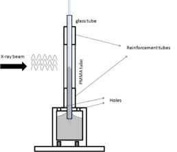
A wicking experiment is performed in a bundle of fibers driven only by capillary forces without the application of vacuum. A specific apparatus was designed to study the wicking experiment capillary rise in a fiber bundle tube over time with detailed measurements of the contact angle at the air/fluid/fiber interfaces as it is sketched in Figure 3a).
The sample consists of a tube made of glass. A bundle of E-glass fibres is introduced into the tube. The fibre volume fraction was close to the target volume fraction in practical manufacturing by vacuum infusion (≈50%).
|
a)
|
b) |
| Figure 3. a) System used to reproduce wicking tests under X-ray radiation for tomography, b) Detail of the local meniscus in the wicking area in contact with the atmosphere formed with resin H (flow direction is vertical). | |
On the other hand, the container at the bottom works as a reservoir, holds the sample and also attaches the system to the rotational stage of an XCT system. The container has the shape of a cylinder and has a cover on the top face. The cover has a short and thin cylinder on the top surface which allows to stick the sample to the container. The cover has four holes since the pressure inside the container must be atmospheric.
The X-ray tomography system allowed the direct access to the meniscus formed locally between the fibers in the contact with the atmosphere, Figure 3b). The results of the measurements over more than twenty contact angle are summarized in Table 2 for three of the fluids analyzed (corn syrup and resins LB and HB). These results were obtained using Synchrotron radiation from both ESRF (Grenoble, Francia) and Petra III Syncrotron (Hamburgo, Aluminio).
| Liquid | θ (º) |
| Corn syrup (70-30) | 75±7.5 |
| ResinLB | 45±5 |
| ResinHB | 35±5 |
3 In-situ micro flow assesment
This set of experiments is devoted to visualize the flow front of resin during the infusion of a single tow using the methodology developed by Vilà et al. [10].
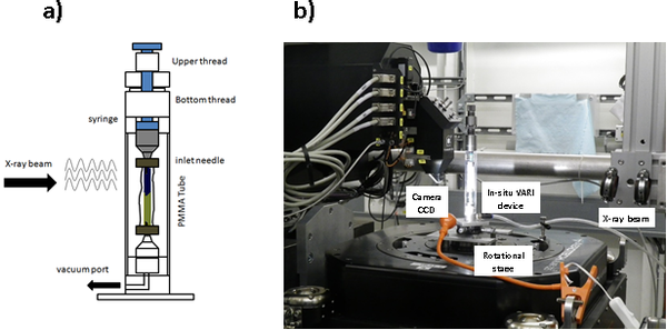
The vacuum is applied through a vacuum pump. The pump used can reach up to -0.95bar. It is connected to the outlet of the device through a catch pot to avoid fluid infiltration into the vacuum pump. The outlet port is situated in a mechanised piece made of Aluminium. A cut head of a 5ml syringe is located on the top part of this piece. Hence, a 0.8 mm in diameter needle can be positioned on the syringe and vacuum can be conducted through both. Another needle is also introduced into the bottom side of the sample. The tested samples during in-situ infiltration correspond to (1, 2 or 3) tows of E-glass inside a polyethylene (PE) vacuum bag. PE was selected due to the higher X-ray resistance with respect to usual Nylon. The vacuum bag has a thickness of 0.4mm while the tow measures 54 mm in length and 4 mm in width. To avoid leaks near the needles connection, a tacky tape is utilised to seal the sample. The remaining perimeter of the bag is thermally sealed in order to avoid tacky tape (a material with high X-ray absorption coefficient) and therefore extra absorbing material in the Field of View (FOV).
The top part of the device was designed to control the height of the reservoir of fluid and the position of the piston. A syringe of 2ml and its piston operate as container and piston. A thread allows to control the height of the holder and fixes it to the device to avoid movements produced during the XCT measurements. Besides, another thread controls the height of the piston. The user can rotate the thread letting the piston to advance and at some point, a drop falls into the needle. Right after, as soon as the liquid deposited in the needle weights enough, the vacuum absorbs it and the fluid infiltrates into the vacuum bag. This method allows an infiltration step-by-step controlled by the user, Figure 4a).
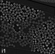
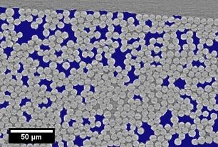
In the following two S-XCT observations of different wetting regimes are presented, Figure 4b). The first case uses corn syrup as fluid and the results are obtained from literature [10]. A representative tomogram of the central region with different local fibre distribution of the tow depicted in Figure 5. It should be remarked that SXCT measurements were carried out under quasi-static conditions and no fluid displacements were detected during data acquisition because they would have led to image blurring effects.
The results obtained in the tomograms clearly showed two different behaviours. First, the infiltration with corn-syrup is produced mainly in open channels with low volume fraction of fibers where the capillary forces are considered negligible. The large contact angle of the corn syrup blend with the glass fibers (θ=75±7.5º) favours the flow through open channels rather than through the highly packed fibers where the capillary forces are considered mainly as drag forces. On the other hand, the flow with Resin LB was much easier in the packed fiber region due to the large capillary forces driven by the lower contact angle (θ=45±5º).
4 References
[1] W.R. Stabler, G.B. Tatterson, R.L. Sadler and A.H. El-Shiekh, 1992 “Void minimization in the Manufacture of Carbon Fiber Composites by Resin Transfer Moulding” SAMPE Q. 23 January, pp 38-42.
[2] Y.K. Hamidi, L. Aktas, M. Altan, Formation of microscopic voids in resin transfer molded compoistes, J.Eng. Mater. Technol. 126 (2004) 420-426.
[3] C.H. Park, A. Lebel, A. Saouab, J. Brard, W.I. Lee, Modelling and simulation of voids and saturarion in liquid composite molding processes. Compos. Part A Appl. Sci. Manuf 42 (2011)
[4] N. Patel, L.J. Lee, Effects of fiber mat architecture on void formation and removal in liquid composite molding, Polym. Compos. 16 (1995) 386-399.
[5] Patel, N., Rohatgi, V., and Lee. J. L., 1995 "Micro Scale Flow Behaviour and Void Formation Mechanism During Impregnation of Uniderctional Stitched Fiberglass Mat", Polym. Eng. Sci., 35. pp. 837-851.
[6] Rohatgi, V., Patel, N. and Lee, J.L., 1996, "Experimental Investigation of Flow Induced Micro-Voids During Impregnation of Unidirectional Stitched Fiberglass Mat." Poly. Compos., 17. pp. 161-170.
[7] J. Verrey, V. Michaud and J-A.E. Manson, “Dynamic capillary effects in liquid composite moulding with non-crimp fabrics” , Composites: Part A 37 (2006) 92-102
[8] S. Azizian and M. Hemmati, “Surface Tension of Binary Mixtures of Ethanol+Ethylene Glycolfrom 20 to 50°C”, J. Chem. Eng. Data 2003, 48,662-663.
[9] M. Li, S. Wang, Y. Gu, Z. Zhang, Y. Li and K. Potter, “Dynamic capillary impact on longitudinal micro-flow in vacuum assisted impregnation and the unsaturated permeability of inner fiber tows” Composites Science and Technology 70 (2010) 1628-1636
[10] J. Vilà, F. Sket, F. Wilde, G. Requena, C. González and J. Llorca, “An in-situ investigation of microscopic infusion and void transport during vacuum-assisted infiltration by means of X-ray computed tomography”, Composites Science and Technology, 119 (2015) 12-19
Document information
Published on 31/03/22
Accepted on 31/03/22
Submitted on 30/03/22
Volume 03 - Comunicaciones Matcomp17 (2019), Issue Núm. 3 - Procesos de Fabricación II y Materiales Avanzados, 2022
DOI: 10.23967/r.matcomp.2022.03.012
Licence: Other
Share this document
Keywords
claim authorship
Are you one of the authors of this document?

