1 Introduction
One of the most important parameters to be considered for studying anisotropic materials (i.e. fiber reinforced composite materials, natural wood and wood products, and mammal bones, among others) are the in-plane shear properties: in-plane shear modulus and in-plane shear strength. On that sense, several test methods are currently available for measuring in-plane (or intralaminar) shear properties of anisotropic materials. Those methods consider a variety of specimen geometries, applied loading, and material configurations [1]. The more accepted methods for determining these in-plane shear properties are:
- The [±45]2s tensile test: ASTM D3518 standard [2].
- The 10º off-axis tensile test.
- The two-rail and three-rail shear tests: ASTM D3518 standard [2].
- The thin-walled tube torsion test: ASTM D5448 standard [3].
- The Iosipescu test: ASTM D5379 standard [4].
- The Arcan test: it is similar to the Iosipescu test.
- The V-notched rail shear test: ASTM D7078 standard [5].
All these tests have been surveyed, described in detail, and compared in terms of advantages and drawbacks, which make them non-ideal methods but complementary ones.
In recent years, other methods for determining the in-plane shear properties under flexural loading have been proposed, being the most important:
- The asymmetric four-point bend (AFPB) test.
- The plate twist test.
The last method considers a three-point bending (3P-B) test stating that normal and shear stresses change from point to point in the specimen, depending on fiber orientation angle and specimen geometry. It has been studied for two loading contact conditions, depending on either lift-off between specimen and fixture supports takes place due to the bending-twisting coupling effects. Such method considers the condition of small displacements and that lift-off between the specimen and the fixture supports occurs. The most important advantages of the off-axis 3P-B method are its simplicity of flexure test configuration, its absence of end-constraint effects on the specimen, there is no need of strain gages to determine the in-plane shear modulus, it considers the deformation of the whole specimen, and the failure can be supposed to start at a precise point. Suitability of the method for carbon-fiber composites has been already done in previous works [8,9]. The aim of this work is to study its suitability for other materials, such as wood.
2 Support and loading application conditions
Due to their anisotropy, unidirectional off-axis composite laminates under flexure show bending–twisting coupling. In the case of a 3-point bending flexure test, these couplings lead to lift-off of the specimen on the fixture supports. This effect was analyzed and proposed as an experimental method in the works of Mujika et al. [6,8,9]. The 3-point bending test for a unidirectional off-axis laminate, as proposed by Mujika et al. [6,8,9], is based on the experimental displacement of the middle point. The following assumptions are made in the analysis in [6], and are thus required conditions:
- Lift-off occurs on the supports, and the contacts between the specimen and the supports are located at only two opposite points. In such case, the problem is statically determinate.
- Applied load is also supposed to be concentrated on the middle point of the specimen.
- The load nose deformation, supports deformations and the particular stress distributions in the vicinity of the load and support points are not considered.
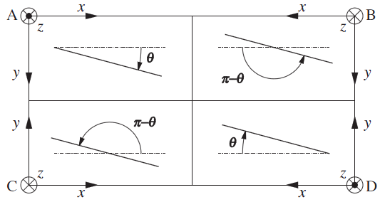
Under these assumptions, uniform distributions of moments and shear forces per unit length along cross sections satisfy equilibrium conditions, except in the vicinity of reactions and load application zones. A typical off-axis bending test, where lift-off is observed, as well as the assumed load configuration and reactions are shown in Figure 1 [1].
2.1 Lift-off on supports
Lift-off on the supports has been considered critical for the validity of the three point off-axis bending test. If lift-off in the support does not occur, the case is statically indeterminate, while if lift-off occurs the problem is statically determinate. All the existing analytical formulation has assumed lift-off on the supports. The frontier between both cases has been established by determining the critical value of the span-to-width ratio, c, for the lift off to occur [8]. Lift-off occurs for c values larger than the critical one, so it is indeed a geometrical condition which could theoretically be accomplished for any material.
The value of the critical span-to-width ratio for lift-off, cLO, is:
|
(1) |
where Sij with i, j = x, y, s are the in-plane compliance coefficients related to bending–twisting effects; L’ is the length of the specimen; and b is the width of the specimen (Figure 1).
2.2 Point contact in load application line
The assumed load application condition has not been verified in previous works dealing with the 3-point off-axis bending test [6,8,9]. However, and as previously explained, the existing analytical formulations are based on the hypothesis of an applied point load in the centre of the specimen. In order to satisfy the condition of a point load in the middle load line, the specimen has to separate from the load application fixture. A downwards lift-off, similar to that in the support lines, is thus required. In this case, due to symmetry in the middle line of the specimen, it is a symmetrical deformation: both extreme zones separate from the load application fixture, and only the central zone remains in contact. In this way, the assumed point load hypothesis is valid.
2.3 Load application cylinder line displacement
In order to verify the downwards displacement condition, the resulting relative displacement wM must be positive for the load application line. As a simplified verification condition, only the relative displacement of the extreme lateral point (1/2, 0) to the centre point in the middle line may be considered, as can be seen in Figure 2, and should be as well positive.
On that sense, based on the displacement of the extreme point located in the middle (load application) line (1/2 , 0), another span-to-width ratio condition can be derived. In this case, span values higher than the limit value cmid deform according to the assumptions in previous works [6], and as a result the point load assumption is adequate. Such limit c value is obtained from the expression]:
|
(2) |
Therefore for the 3-point off-axis bending test two span-to-width ratio conditions are required [1]:
c > cLO (1) and c > cmid (2).
The value of the parameter cmid must be in the real domain, so the square root term must be positive. This condition may be expressed then as:
|
(3) |
Then, the limit cmid span length is not related to any geometrical parameter, only to material properties. It proves the possibility that for a certain material, the required point load application condition could not be achieved. Consequently, the off-axis bending method, with its assumptions would consider not valid.
The condition for the suitability of the 3-point off-axis bending method for the analyzed material is defined, from (3), with the γmid parameter as:
|
|
(4) |
If γmid is in the range between zero and one, 0 < γmid < 1, the off-axis bending method is not valid. It would be appropriate, in its present formulation, in any other case [1].
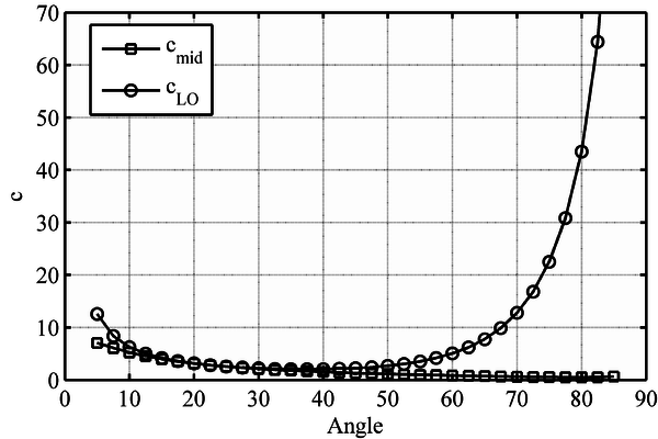
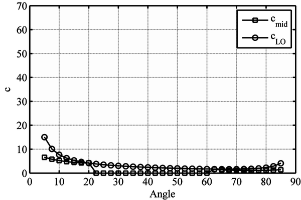
A plot of the two c limit values, cLO [9] and cmid [1], for two different materials, carbon fiber and beechwood, is shown in Figure 3a and 3b respectively. In those cases where no real solution exists, cmid is plotted as zero. Both parameters show a similar trend. Besides, the value for the cLO parameter is usually higher than the cmid. Hence, the verification of the cLO condition is usually enough to verify the point load application condition as well. Nevertheless, for some materials (e.g. beechwood), in a certain orientation range, from 20º to 60º, the existing 3-point off-axis bending method is not valid [1].
3 Verification for different materials
As stated in the previous Section, for certain materials the load hypotheses assumed in the 3-point bending off-axis method may not be verified. In this Section, a parametric analysis is accomplished in order to verify the suitability of the off-axis bending method to existing composite materials.
The elastic constants of several man-made composites (glass fiber, carbon fiber, kevlar fiber) and natural composites: spruce (softwood) and beech (hardwood), are presented in Table 1.
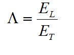
Two parameters, based on the elastic moduli ratio, are defined:
|
|
(5) |
|
|
(6) |
where EL and ET are the longitudinal and transverse elastic moduli, and G is the shear modulus.
Table 1. A representative set of composite materials, both man-made and natural [1].
| Composite material | EL [GPa] | ET [GPa] | G [GPa] | Τ | |
| Boron/epoxy [10] | 201 | 21.7 | 5.4 | 9.26 | 4.02 |
| Carbon/epoxy [10] | 142 | 10.3 | 7.2 | 13.78 | 1.43 |
| Kevlar/epoxy [10] | 87 | 5.5 | 2.2 | 15.82 | 2.50 |
| E-glass/epoxy [10] | 39 | 8.6 | 3.8 | 4.54 | 2.26 |
| Beech (clear wood) [11] | 11.82 | 0.59 | 1.36 | 20.03 | 0.43 |
| Spruce (clear wood) [11] | 18.28 | 0.23 | 0.62 | 79.48 | 0.37 |
| D40 Timber (hardwood) [12] | 11.00 | 0.75 | 0.70 | 14.67 | 1.07 |
| C24 Timber (softwood) [12] | 11.00 | 0.37 | 0.69 | 29.73 | 0.54 |
As can be seen in Table 1, ratio (5) becomes higher for natural composites, and lower for man-made. Conversely, the Τ ratio (5) is high for man-made materials, and usually lower than one for natural materials such as softwood [1].
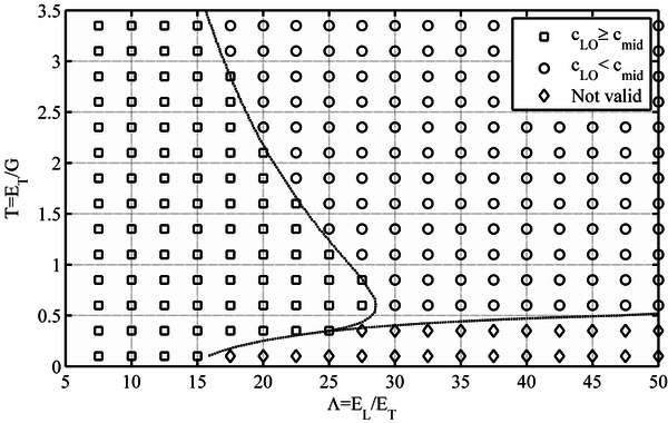
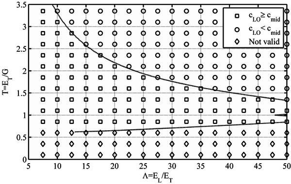
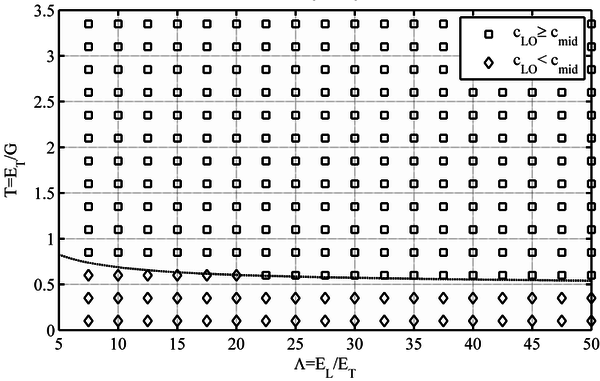
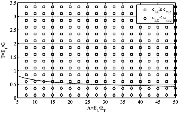
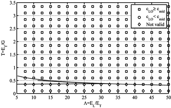
In order to analyze the validity of the 3-point off-axis bending method, the defined material ratios, and Τ, for different fiber orientations and the derived verification condition γmid (4), is plotted in Figures 4 to 8. As it may be seen, the Τ ratio plays a major role in the validity of the off-axis bending method. As a rule of thumb, it may be established that those materials with a Τ ratio lower than 0.5 are usually not suitable for the 3-point off-axis bending test.
When the influence of the fiber orientation is analyzed, several differences arise, mainly related to the Τ/ slope of the limit line between the valid and non-valid materials zones. For the 15º fiber orientation (Figure 4), the slope is positive, that is, Τ value increases with increasing . In the 30º fiber orientation (Fig. 5), such limit line becomes horizontal when Τ ≈ 0.6. For higher fiber orientations (i.e. 45º, 60º and 75º), the slope is negative, and Τ value diminishes with increasing , as can be seen in Figures 6, 7 and 8 respectively. The 45º fiber orientation is the most restrictive (Figure 6), that is, the orientation for which a higher number of materials would estimate not valid. The non-valid zone diminishes for higher angles, such as 60º and 75º, (Figures 7 and 8) [1].
In addition, for those material ratios in which the load line displacement condition is verified, a comparison between the cLO (support lift-off) and cmid (load line) limits is also plotted in Figures 6-8. For a number of materials the previously found cLO condition is lower than the cmid parameter required for the load displacement condition to be verified. Consequently, in those cases, cmid is the minimum span-to-width ratio required for the test to be valid [1].
4 Conclusions
In this paper the off-axis three-point bending test for characterizing in-plane shear properties of anisotropic materials (i.e. fiber reinforced composite materials and natural wood) has been analyzed theoretically. In this method normal and shear stresses vary point to point through the specimen depending on both material configuration (i.e. fiber orientation angle) and geometrical parameters (i.e. span-to-width ratio, c). Bending–twisting coupling due to the marked anisotropy of unidirectional fiber reinforced materials is featured on off-axis laminates under flexure loading. Such coupling effect gives rise to two possible situations on both support and loading application conditions: a lift-off of the specimen on the fixture supports, and a point contact in load application line.
Besides to support and loading restrictions, material elastic constants (i.e. longitudinal, transversal and shear elastic moduli: EL, ET, G) have an effect on the application of mentioned method in order to determine in-plane shear properties of anisotropic materials. Thereby, this work presents an analytical approach for investigating the conditions to assure the applicability of the off-axis 3 point-bending test. Main results reveal that, regarding the span-to-width ratio, lifting-off condition cLO, is usually higher than the cylinder line load displacement condition cmid. Therefore assessing the cLO condition is generally enough to verify also the load application cmid condition. As a consequence, usually the minimum span-to-width ratio required for the test to be valid is cLO.
Regarding the ratios between elastic moduli, = EL/ET and Τ = ET/G, results indicate that ratio is higher for natural wood than for fiber reinforced plastics, and on the contrary Τ ratio is high for man-made composite materials, and even lower than one for some natural materials. As Τ ratio has a greater influence than ratio in the validity of the off-axis three-point bending test, materials with a Τ ratio lower than 0.5 are not usually suitable for such method (i.e. wood, as beech and spruce). In addition, concerning material configuration, it has been found that 45º is the most restrictive fiber orientation angle for which the analyzed test has a larger number of materials that are not considered valid.
Currently, since the analyzed model is not suitable for some composite materials as natural wood, another model is being developed. The authors of this paper are in the process of verification of the new formulation in the light of experimental results.
Acknowledgements
The support of the Wood Chair, joint initiative of the Government of Navarre and the University of Navarra, is greatly acknowledged. The authors wish to express their gratitude to Miguel Yurrita, who helped in a preliminary phase of this research.
Referencias
[1] J.M. Cabrero, G. Vargas, Applied Mathematical Modelling 39, 17, pág. 5265-5277 (2015). https://doi.org/10.1016/j.apm.2015.03.031
[2] ASTM D3518/D3518M–94. Standard Test Method for In-Plane Shear Response of Polymer Matrix Composite Materials by Tensile Test of a ±45º Laminate (2007).
[3] ASTM D5448/D5448M–93. Standard Test Method for Inplane Shear Properties of Hoop Wound Polymer Matrix Composite Cylinders (2006).
[4] ASTM D5379/D5379M–05. Standard Test Method for Shear Properties of Composite Materials by the V-Notched Beam Method (2005).
[5] ASTM D7078/D7078M–05. Standard Test Method for Shear Properties of Composite Materials by V-Notched Rail Shear Method (2005).
[6] F. Mujika, A. Valea, P. Gañan, I. Mondragon, Journal of Composite Materials 39, 11, pág. 953-980 (2005). https://doi.org/10.1177/0021998305048735
[7] G. Vargas, F. Mujika, Journal of Composite Materials 44, 21, pág. 2487-2507 (2010). http://dx.doi.org/10.1177/0021998310369601
[8] F. Mujika, I. Mondragon, Journal of Composite Materials 37, 12, pág. 1041-1066 (2003). http://dx.doi.org/10.1177/0021998303037012001
[9] F. Mujika, A. de Benito, I. Mondragon, Journal of Composite Materials 37, 13, pág. 1191-1217 (2003). https://doi.org/10.1177/0021998303037013004
[10] I.M. Daniel, O. Ishai. Engineering Mechanics of Composite Materials. Oxford University, New York (1994).
[11] D. Grosser, B. Zimmer. Einheimische Nutzhölzer und ihre Verwendung. 4, Informationdienst Holz (1998).
[12] EN1995-1-1:2004. Eurocode 5. Design of Timber Structures. Part 1–1: General – Common rules and rules for buildings (2004).
Document information
Published on 19/10/17
Accepted on 19/10/17
Submitted on 19/10/17
Volume 01 - Comunicaciones Matcomp17 (2017), Issue Núm. 1 - Comportamiento en Servicio de los Materiales Compuestos, 2017
DOI: 10.23967/r.matcomp.2017.10.016
Licence: Other
Share this document
Keywords
claim authorship
Are you one of the authors of this document?


