1 Introduction
Using Carbon fibre reinforced polymers (CFRP) in the automotive industry can reduce up to 70% of a cars weight and dissipate up to five times higher impact energies than metals [1]. However, the high manufacturing cost and cycle times associated to techniques such as prepreg + autoclave or Resin Transfer Moulding (RTM) have limited a wider use of CFRP [2]. RTM is a manufacturing process that has been applied for many years and is therefore well established [3], especially in aeronautic industry. However, in structural applications where higher fibre volume fractions (>50 %) are needed, the impregnation of the preform is more difficult because the permeability decreases; this results in longer mould filling times, and a higher probability of producing defects such as incomplete impregnation of the preform, poorly impregnated areas, misalignment of fibres or the generation of high porosity and voids.
CRTM is a variation of RTM, which can help to overcome some of this difficulties [3, 4]. The process is very similar to RTM, but in the injection stage, the mould is kept a bit open, so the permeability of the preform increases, and sometimes even a gap is produced between the preform and the upper mould. This way, the resin can be injected very fast. After injecting all the needed resin, the mould is closed to the final thickness of the part, forcing the resin to flow transversally (through the thickness) instead of flowing in-plane of the component (like in RTM). The resin flow pattern in CRTM is complex, because during the injection stage the resin flows through the gap, but part of it also goes into the preform [5], and the final impregnation pattern will affect the resin flow during the compression stage, the force needed and the quality of the final component. Therefore, it is important to understand all the phenomena that take place and adequately characterize all the parameters that influence the process in order to optimize it in order to reduce cycle times without affecting the quality of the final component.
The main objective of this work is to manufacture a CFRP sports car bonnet using CRTM in a very short time, analysing and optimising the different phases that take place during the process. This work has been performed in the frame of ADVANCRTM European project (Eurostars). The partners of the project are Alpex (Austria), Fagor Arrasate – Mondragon Unibertsitatea (Spain), FHNW (Switzerland), Roctool (France) and Riba (Italy).
2 Car bonnet description
The original car bonnet is shown in figure 1. The materials chosen for this study are a 0/90 non-crimp fabric of HR 50k Carbon fibre of 300 g/m2 (HPT300 C090) and a fast curing epoxy from Huntsman (XB 3538 /Aradur® 3475). An aesthetic external woven carbon fibre layer was also included. The configuration of the layup has been defined for having equivalent mechanical properties as the original bonnet (manufactured by prepreg + autoclave). The thickness of the bonnet is not constant, varying in different zones from 1 to 1,6 mm.
3 Analysis of the CRTM process of the car bonnet
The goal is to analyse the possibility of manufacturing the part with a CRTM cycle time of less than 4 min. In order to optimise the CRTM process, the resin injection stage has been simulated. For that, both the reinforcement and the matrix must be characterised.
3.1 Characterization of the reinforcement permeability
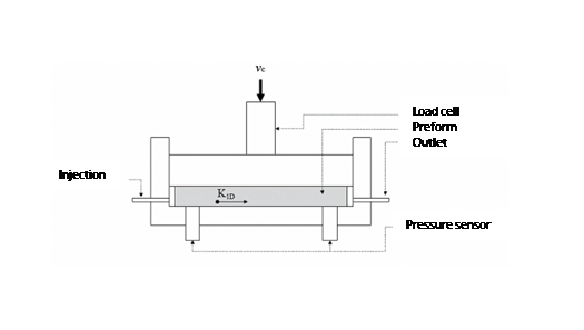
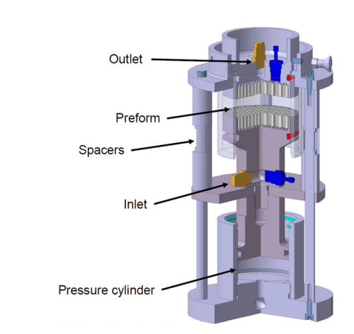
The permeabilities of the carbon non-crimp fabric have been determined experimentally in both directions, in-plane and through the thickness (figures 2 and 3).
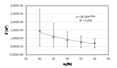
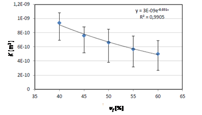
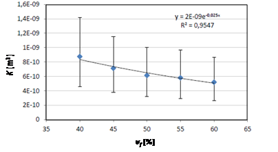
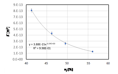
The results for in-plane permeability for 0º, 90º and ±45º and for different fibre volume fractions are shown in figures 4, 5 and 6 respectively. Through the thickness permeability is shown in figure 7.
It can be seen that the permeability reduction as fibre volume fraction increases is almost linear in-plane, with significant differences for 0º, 90º and ±45º. On the other hand, the permeability in the transverse direction is three orders of magnitude lower (which implies that impregnation in that direction is more difficult), and it decays exponentially as fiber volume content increases.
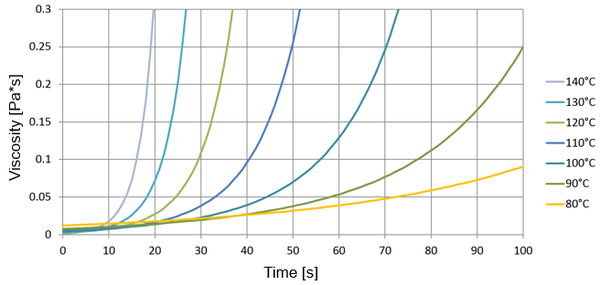
For the cure kinetics, a modified Kamal-Sourour model has been used based on DSC analysis (Figure 8),
|
|
(1) |
|
|
(2) |
|
|
(3) |
where is the curing degree, and and are constants.
As rheology model, Castro Macosko model has been used,
|
|
(4) |
|
|
(5) |
where is the viscosity, is the shear rate, are constants and is temperature. Both cure kinetics and rheological measurements were performed with state-of-the-art laboratory equipment as described in a previous work [6].
3.2 Isothermal vs variothermal curing
In this study both, isothermal and variothermal approaches have been studied theoretically. In the isothermal approach, the mould can be heated using traditional water or oil tempering systems; however, the thermal inertia of these kind of moulds is very high i.e. 5 hours for increasing mould temperature from 20 to 85 ºC.
As an alternative, induction-heating systems only heat a thin layer of the metallic surface of the mould, which is directly contacting the part. This way, the thermal inertia is reduced drastically.
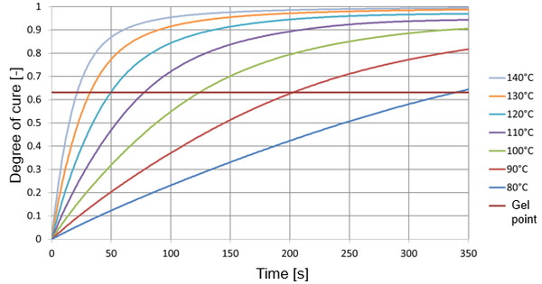
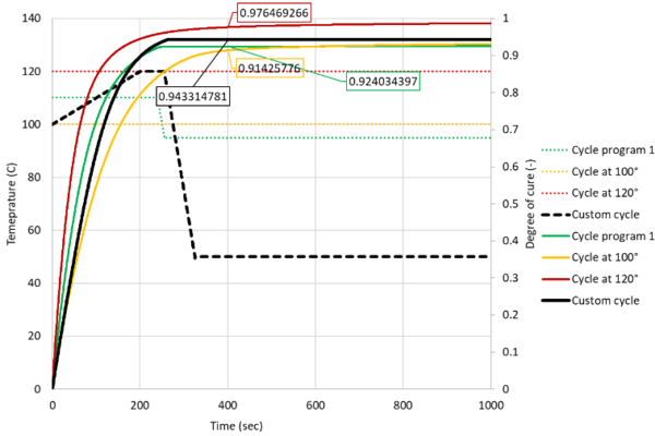
In figure 10 the cure progression of the epoxy resin is shown for different cure cycles dependant on the temperature profile.
In table 1 isothermal processes are compared with variothermal ones in terms of degree of cure, leftover time in liquid state and power consumption.
| Scenarios | 1 | 2 | 3 | 4 | 5 |
| Initial temp [ºC] | 100 | 110 | 120 | 115 | 100 |
| Final temp [ºC] | 100 | 110 | 120 | 125 | 120 |
| Injection time budget [s] | 27 | 27 | 27 | 27 | 27 |
| Mould closing time budget [s] | 5 | 5 | 5 | 5 | 5 |
| Calculate for last resin injected?
Delay=injection time, at 23ºC |
no | no | no | no | no |
| Final time, required liquid state [s] | 32 | 32 | 32 | 32 | 32 |
| Start time of heating [s] | 0 | 0 | 0 | 0 | 0 |
| Final time of heating [s] | 240 | 240 | 240 | 240 | 240 |
| Heat-up time window [s] | 240 | 240 | 240 | 240 | 240 |
| Heating ramp [ºC/s] | 0 | 0 | 0 | 0.042 | 0.083 |
| Cooling ramp [ºC/s] | 1 | 1 | 1 | 1 | 1 |
| Rest temp [ºC] (lower than start) | 95 | 95 | 95 | 95 | 95 |
| Hold time at max. temp [s] | 0 | 0 | 0 | 0 | 0 |
| Cooling time [s] | 5.2 | 15.2 | 25.2 | 30 | 25 |
| Total cycle time [s] | 245.2 | 255.2 | 265.2 | 270 | 265 |
| Degree of cure @ Total cycle time | 0.85 | 0.92 | 0.96 | 0.96 | 0.93 |
| Degree of cure @ Final liquid time | 0.22 | 0.33 | 0.47 | 0.41 | 0.23 |
| Leftover time still in liquid state [s] | 57.5 | 23.5 | 3.5 | 10.5 | 45.0 |
| Power [kW] | 15 | 15 | 15 | 292 | 573 |
Based on the results shown in table 1 and figure 10, the following statements can be made:
The higher the final mould temperature, the higher is the degree of cure after the total process cycle time.
Taking into account a curing degree below 95 % would not lead to sufficient mechanical and thermal properties, a mould temperature below 120 °C should be avoided. Additionally, the left over time of the resin being in a liquid state should be high enough (e.g. < 10 s) for a good impregnation of the fabric.
Considering these two prerequisites (enough time for impregnation of the fabric with low viscous resin and high degree of cure at the end of the cycle) one can see the advantage of a variothermal cycle: In scenario 4 (table 1) the resulting degree of cure would be 96 % with a leftover time of 10.5 seconds.
In order to save energy and costs for the variothermal system, the temperature delta in the variothermal process should be as small as possible. In scenario 5 (table 1) one can see that the leftover time would be 45 s but the degree of cure would be only 93 %. Additionally, an energy source with 573 kW would be needed. For the calculation of the power the mould size (l = 2.2 m, w = 2.1 m, d = 0.3 m), mould mass, heating and cooling cycle, ramp time, injection time, heat time and heat loss were taken into account.
3.3 Simulation of the injection stage
The through-plane impregnation has been simulated with Autodesk® Moldflow® using a geometrically simplified model, and the same models for the cure kinetics and rheology as described in equations (1)-(3) and (4)-(5). Only the impact of shear was neglected. The permeability for the preform was applied according to the measurements from figure 4 to 7. The permeability for the gap depends on the thickness of the gap:
|
|
(6) |
Preliminary simulations were carried out to check the suitability of Moldflow® for this process. Especially the meshing was demanding and lead to high aspect ratios of the elements because a good resolution was needed over the thickness for the large-area but thin bonnet. The detailed parameters of the simulation can be found in table 2:
| Reactive viscosity model | Kinetic of n-th order | ||
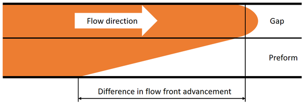
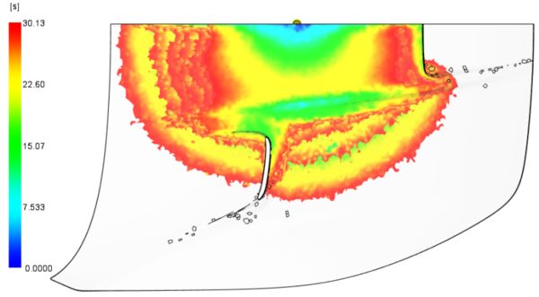
Significant differences are observed between flow front advancement in the gap and in the preform (figures 11, figure 12 and table 3. This advancement depends mostly on gap thickness, when considering the same preform.
| Gap thickness [mm] | Difference in flow front advancement [mm] |
| 0.5 | 200 |
| 1 | 342 |
A smaller gap (and hence higher flow resistance) decreases the difference in the flow front advancement when filling large flat cavities such as a bonnet by injection compression moulding.
4 Manufacturing of the car bonnet
4.1 Description of the mould
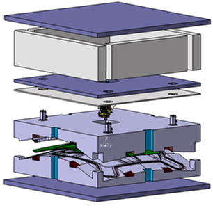
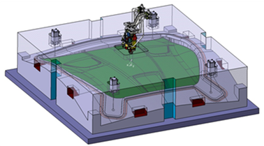
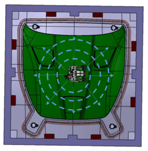
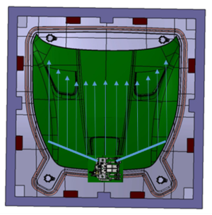
The mould has been built in aluminium, as it is not intended for an intensive industrial use. The overall size of the mould is 2140mm × 2140mm × 700 mm and has a total mass of around 6000 kg. An exploded view of the mould is shown in figure 13. In figure 14 the mould is shown closed, all together with the injection head and the component. The mould has four vacuum points in the four corners, and the possibility of injecting the resin through a centred injection point, through an injection point located at the front of the bonnet. This way, two different injection strategies can be tested: radial (centred) and linear (front to rear), as shown in Figure 15 (a) and (b), respectively.
 (a) (a)
|
 (b) (b)
|
The mould has been manufactured including a traditional water/oil heating circuit; taking into account the big size of the mould, the power needed by the induction system for the variothermal tests was too high.
4.2 Manufacturing parameters
For the experimental manufacturing tests, it has not been possible to replicate the theoretically analysed cases. The thermal inertia of such a big mould together with the heating system available, allowed a maximum test temperature of only 100ºC (and most of the tests have been performed at around 80ºC). For this reason, the target cycle time has been increased to 30 min.
When manufacturing the bonnet, different parameters have been considered:
Mould parameters:
a) Gap size: depending on the gap size, the resin can be injected faster (bigger gap) or slower (smaller gap). However, a smaller gap means that the resin will be more dispersed on the preform, occupying a larger area, which in consequence would produce a better-impregnated preform once the mould is closed.
b) Temperature of the mould: The resin is a fast curing epoxy resin; the temperature of the mould will highly affect the time needed for the resin to cure. Higher mould temperatures will reduce the curing time, but can also affect the filling time since if the viscosity can increase while the mould is being filled, and this could make more difficult and even prevent the total filling of the mould.
c) Position of the injection and vacuum points: There are two injection points that can be used (one at a time). There are also four vacuum points that can be connected and disconnected during the injection and compression phases in order to try to direct the flow to specific directions.
Injection machine parameters:
d) Resin volume: The theoretical resin volume needed is determined, but more resin must be injected considering that some of the resin will fill the distribution channels, tubes, injection point or vacuum holes.
e) Flow-rate and injection pressure: These parameters will determine the injection time and must be carefully selected; if the viscosity of the resin is too high for the injection machine to inject the selected quantity, the system will not be able to function correctly.
f) Resin temperature. If the resin is kept warmer in the deposit of the injection machine (before it is mixed with the catalyst) the resin will be injected more easily than if it is kept cooler. In this case the influence of the resin temperature has not been analysed, but previous tests have demonstrated that a set point temperature of the resin deposit of 60º C was needed in order to assure a correct function of the injection machine.
Considering all these parameters, and taking into account the time limitation for this phase, the influence of only some of them has been analysed (Table 4).
| Test number | Gap (mm) | Mould temperature [ºC] | Resin temperature [ºC] | Injection strategy | Resin volume [l] | Injection pressure [bar] | Closing velocity [mm/s] | Vacuum [yes/no] | time | ||
| Injection (s) | Compression [s] | Curing [min] | |||||||||
| 1 | 3.3 | 82 | 60 | Centre | 1.8/1.8 | 5 | 1 | - | 30 | 5 | 30 |
| 2 | 1.3 | 86 | 60 | Centre | 0.6/1.8 | 5 | 1 | Yes | 180 | 5 | 30 |
| 3 | 3.3 | 82 | 60 | Centre | 0.5/2.2 | 5 | 1 | - | 180 | 5 | 30 |
| 4 | 3.3 | 83 | 60 | Centre | 2.2/2.2 | 5 | 1 | Yes | 30 | 5 | 30 |
| 5 | 3.3 | 80 | 60 | Front | 2.2/2.2 | 5 | 1 | Yes | 108 | 5 | 30 |
| 6 | 3.3 | 75 | 60 | Front | 2.2/2.2 | 5 | 1 | Yes | 28 | 5 | 20 |
| 7 | 3.3 | 99 | 60 | Centre | 2.2/2.2 | 5 | 1 | Yes | 60 | 5 | 30 |
4.3 Results
After having carried out the bonnet manufacturing tests, some of the observations concerning the results are set out below.
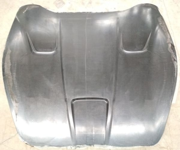
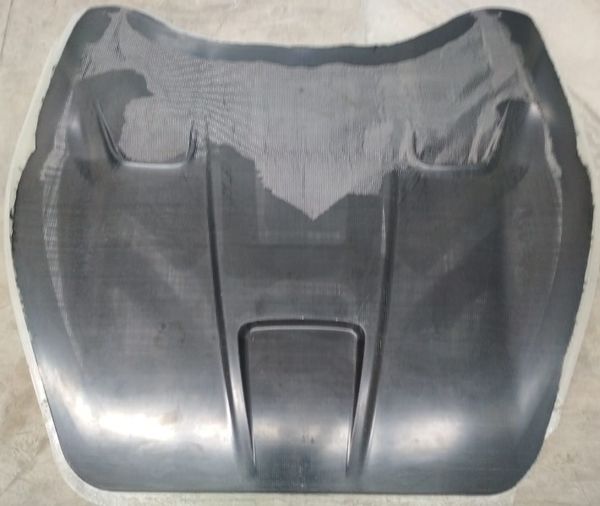
In test nº1 the process has been ok, but not enough resin was injected, resulting in a non-fully impregnated part (figure 16).
In test nº2 the gap size has been too small, the injection machine has not been able to inject all the resin into the mould (figure 17).
In test nº 3 the preform has not been previously compacted, and the injection machine has not been able to inject the resin into the mould. The result (figure 18) is similar to test number 2.
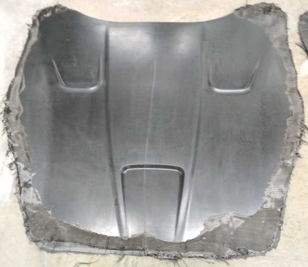
The test nº 4 has given the best result (figure 19), even if the presence of race-tracking has left some dry spots in the part.
In test number 5 there was a problem with the valve of the injection machine, and almost no resin was injected to the preform.
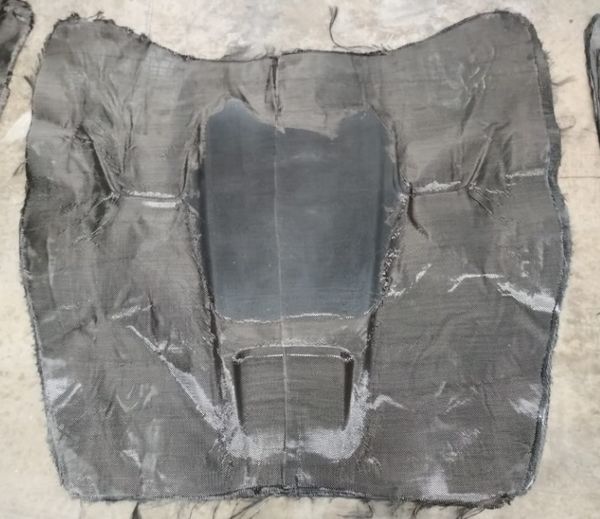
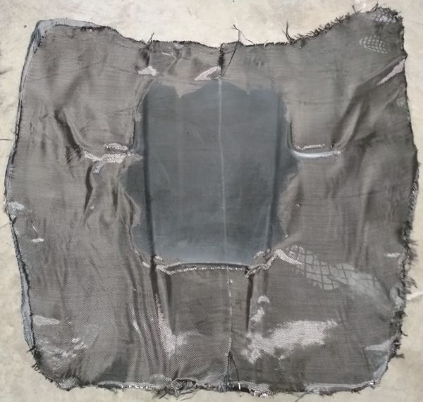
In test number 6 resin was injected from the front part of the bonnet, but race tracking occurred in the perimeter of the preform. The resin did not impregnate a big central part of the preform (figure 20).
In test number 7 the mould has been at a higher temperature (99ºC), which has increased the viscosity of the resin very fast; in consequence, the injection machine has not been able to inject all the resin, so the injection phase had to be stopped in order to preserve the injection machine itself from being blocked with cured resin.
5 Conclusions
In this work, the CRTM manufacturing process of a sports car has been studied. The in-plane and through-the-thickness permeabilities of the reinforcement have been measured for different fibre content values. An almost linear decay of permeability has been observed as fibre content increases in-plane from 40% to 60%, with significant differences depending on the fibre direction, being ±45º the one that showed the least permeability.
Through-the-thickness permeability has been three orders of magnitude lower than in-plane, and it decays exponentially as fiber volume content increases for the same fibre content range.
The curing kinetics of the resin has been modelled using a modified Kamal-Sourour model, and a Castro Macosko model has been used as rheology model. The cure progression of the resin has been defined for different cure cycles dependant on the temperature profile. Some of these scenarios include isothermal profiles, while others include variothermal approaches. There are two scenarios in which a 95% of curing degree is reached in 240 s: One isothermal (with a mould temperature of 120ºC), and the other variothermal (from 115ºC to 125ºC). The advantage of using a variothermal approach has been demonstrated because the resin leftover time still in liquid state is three times bigger; however, the amount of energy needed for the variothermal scenario also increases drastically.
It has not been possible to replicate the theoretical analysis experimentally, mainly due to the high thermal inertia of the mould. In consequence, a lower mould temperature has been chosen and a new target cycle time of 30 min has been established. Only one of the tests performed resulted in an almost total impregnated component.
Acknowledgements
The authors gratefully acknowledge the support of the European Union via project ADVANCRTM (10032/14/22619/Ae), the Basque Government (Programa Predoctoral de Formación de Personal Investigador No Doctor, PRE_2014_1_402) and Diputación Foral de Guipuzkoa (OF 144/2014).
References
[1] A. Esnaola, I. Tena, J. Aurrekoetxea, I. Gallego and I Ulacia, Composites Part B: Engineering 85, 1 (2016).
https://doi.org/10.1016/j.compositesb.2015.09.007
[2] M.G. Bader, Composites Part A: Applied Science and Manufacturing 33, 913 (2002).
https://doi.org/10.1016/S1359-835X(02)00044-1
[3] C.D. Rudd, A.C. Long, K.N. Kendall, C.Mangin. Liquid Moulding Rechnologies, 1 (1997)
https://doi.org/10.1533/9781845695446.1
[4] M. Baskaran, I. Ortiz de Mendibil, M. Sarrionandia, J. Aurrekoetxea, J. Acosta, U. Argarate and D. Chico. 16th European Conference in Composite Materials, Seville, Spain, n.d.: 22-622-26 June (2014)
https://doi.org/10.1002/admt.201800271
[5] P. Simaneck and S.G. Advani, Revue européenne des elements finis, 14, 777 (2005)
[6] R. Geinsberger, J. Maldonado, N. Bahamonde, A. Keller, C. Dransfeld, K. Masania. Composites Part B: Engineering 124, 182 (2017).
Document information
Published on 31/03/22
Accepted on 31/03/22
Submitted on 31/03/22
Volume 03 - Comunicaciones Matcomp17 (2019), Issue Núm. 3 - Procesos de Fabricación II y Materiales Avanzados, 2022
DOI: 10.23967/r.matcomp.2022.03.013
Licence: Other
Share this document
Keywords
claim authorship
Are you one of the authors of this document?

