m (Ping Li moved page Draft Li 939997522 to Review 932178682507) |
|||
| Line 36: | Line 36: | ||
===1. Introduction=== | ===1. Introduction=== | ||
| − | Coastal areas are mostly soft soil foundation, which needs to be treated before construction. Static pile technique is a common method to deal with soft soil foundation, which has been widely used in the world | + | Coastal areas are mostly soft soil foundation, which needs to be treated before construction. Static pile technique is a common method to deal with soft soil foundation, which has been widely used in the world <sup>[1-3]</sup>. Although the bearing capacity of the foundation can be improved by pressing the static pile into the soil by the static pile pressing machine, it is inevitable to squeeze the soil in the process of pile installation, resulting in disturbance of the surrounding soil around the static pile <sup>[4-6]</sup>. Further, pile installation could produce high excess pore pressure, which results in the slow development of pile bearing capacity <sup>[7]</sup>. High excess pore pressure could also cause some negative effects on the pile and surrounding soil, including deviation of pile and ground heave <sup>[8-10]</sup>. Therefore, it is necessary to put forward a set of prediction scheme to evaluate the excess pore pressure after pile installation, so that engineers can deal with the risks in advance. |
| − | <span id='_Hlk58238552'></span>Axisymmetric consolidation model is often used to evaluate the dissipation of excess pore pressure after pile-driving. | + | <span id='_Hlk58238552'></span>Axisymmetric consolidation model is often used to evaluate the dissipation of excess pore pressure after pile-driving. Randolph and Wroth (1979) <sup>[10]</sup> first proposed an analytical solution of axisymmetric consolidation around an impermeable pile considering radial drainage through pile-driving test. Subsequently, in the theoretical study on the axisymmetric consolidation of the soil around the impermeable pile, Guo (2000) <sup>[11]</sup> proposed the analytical solution considering viscoelastic soil, and Gao and Shi (2008) <sup>[12]</sup> proposed the analytical solution considering both radial and vertical drainage. Recently, a permeable pile technique has been developed to accelerate the consolidation rate of foundation soil. Therefore, some scholars have further studied axisymmetric consolidation around a permeable pile <sup>[13, 14]</sup>. |
| − | <span id='OLE_LINK3'></span><span id='_Hlk73534518'></span>It should be emphasized that all above-mentioned studies are limited to undisturbed soils. In fact, the existing field data and test data show that the disturbance effect on the soil around the pile is inevitable in the process of pile installation | + | <span id='OLE_LINK3'></span><span id='_Hlk73534518'></span>It should be emphasized that all above-mentioned studies are limited to undisturbed soils. In fact, the existing field data and test data show that the disturbance effect on the soil around the pile is inevitable in the process of pile installation <sup>[15, 16]</sup>. In general, in the process of pile installation, radial compression will occur to the soil around the pile, leading to the decrease of the radial permeability coefficient of the disturbed soil, which will lead to the decrease of the radial drainage performance of the soil. When the vertical drainage distance is long, the soil drainage path is mainly radial. In this case, the disturbance effect of soil should not be ignored. |
| − | Similar to pile installation, the prefabricated vertical drains (i.e., PVDs) installation has been fully studied | + | Similar to pile installation, the prefabricated vertical drains (i.e., PVDs) installation has been fully studied <sup>[17-20]</sup>. Compared with the smear effect by PVD installation <sup>[21-25]</sup>, the disturbance effect induced by pile installation is much more significant due to its bigger radius. Thus, it is of significance to study the consolidation of soil around the pile considering disturbance effect. Additionally, the growth rate of pile bearing capacity could be overestimated by using the current consolidation model, which leads to some unknown risks (e.g., excessive settlement and insufficient bearing capacity) and reducing the accuracy of building’s reliability analysis <sup>[9, 26, 27]</sup>. Therefore, whether it is the study of consolidation theory of soil around pile or the subsequent analysis of pile bearing capacity, the study of consolidation theory considering disturbance effect is of great significance. Unfortunately, there is no an analytical solution to axisymmetric consolidation of soil considering the disturbance effect around a pipe pile. |
<span id='_Hlk73106423'></span><span id='_Hlk73000322'></span>In order to better predict the dissipation process of excess pore pressure and the increase process of pile bearing capacity after piling, it is necessary to further optimize the existing consolidation theory. On the condition that the disturbance effect cannot be ignored, this paper presents an analytical solution to axisymmetric consolidation of soil considering the disturbance effect around a pipe pile on the basis of previous studies. Fourier transform and separation of variables are used to solve the problem, and the solution is calibrated by degradation analysis and FEM. Subsequently, the distribution of excess pore pressure along vertical and radial directions are analyzed by graphical interpretation. Moreover, the concept of the dimensionless average excess pore pressure at pile-soil interface is put forward and the influence of disturbance parameters on it is analyzed. Most importantly, the validity of the solution is demonstrated by comparing with test data. | <span id='_Hlk73106423'></span><span id='_Hlk73000322'></span>In order to better predict the dissipation process of excess pore pressure and the increase process of pile bearing capacity after piling, it is necessary to further optimize the existing consolidation theory. On the condition that the disturbance effect cannot be ignored, this paper presents an analytical solution to axisymmetric consolidation of soil considering the disturbance effect around a pipe pile on the basis of previous studies. Fourier transform and separation of variables are used to solve the problem, and the solution is calibrated by degradation analysis and FEM. Subsequently, the distribution of excess pore pressure along vertical and radial directions are analyzed by graphical interpretation. Moreover, the concept of the dimensionless average excess pore pressure at pile-soil interface is put forward and the influence of disturbance parameters on it is analyzed. Most importantly, the validity of the solution is demonstrated by comparing with test data. | ||
| Line 61: | Line 61: | ||
<div class="center" style="width: auto; margin-left: auto; margin-right: auto;"> | <div class="center" style="width: auto; margin-left: auto; margin-right: auto;"> | ||
| − | [[Image: | + | [[Image:Review_932178682507-image5.png|246px]] </div> |
<div class="center" style="width: auto; margin-left: auto; margin-right: auto;"> | <div class="center" style="width: auto; margin-left: auto; margin-right: auto;"> | ||
| Line 70: | Line 70: | ||
====2.2 Governing equations==== | ====2.2 Governing equations==== | ||
| − | <span id='_Hlk52300410'></span>According to the findings of | + | <span id='_Hlk52300410'></span>According to the findings of Randolph and Wroth (1979) <sup>[10]</sup>, the excess pore pressure generated during pile-driving will dissipate in both radial and vertical directions. Therefore, the following governing equations are established: |
{| class="formulaSCP" style="width: 100%; text-align: center;" | {| class="formulaSCP" style="width: 100%; text-align: center;" | ||
| Line 77: | Line 77: | ||
{| style="text-align: center; margin:auto;" | {| style="text-align: center; margin:auto;" | ||
|- | |- | ||
| − | | <span id='ZEqnNum681049'></span> [[Image: | + | | <span id='ZEqnNum681049'></span> [[Image:Review_932178682507-image6.png|306px]] |
|} | |} | ||
| style="width: 5px;text-align: right;white-space: nowrap;" | (1) | | style="width: 5px;text-align: right;white-space: nowrap;" | (1) | ||
| Line 89: | Line 89: | ||
====2.3 Initial and boundary conditions==== | ====2.3 Initial and boundary conditions==== | ||
| − | The initial pore pressure distribution of soil around a pile after pile-driving can generally be obtained through numerical simulation or experimental test | + | The initial pore pressure distribution of soil around a pile after pile-driving can generally be obtained through numerical simulation or experimental test <sup>[28-30]</sup>. Here, the initial excess pore pressure is generalized expressed as |
{| class="formulaSCP" style="width: 100%; text-align: center;" | {| class="formulaSCP" style="width: 100%; text-align: center;" | ||
| Line 384: | Line 384: | ||
| − | The initial excess pore pressure is mainly distributed in the plastic zone. It decays along the radius direction and increases along the depth. It is also worthy to highlight the fact that the initial excess pore pressure is calculated after pile-driving, at which time the excess pore pressure of the upper part of surface soil has been completely dissipated | + | The initial excess pore pressure is mainly distributed in the plastic zone. It decays along the radius direction and increases along the depth. It is also worthy to highlight the fact that the initial excess pore pressure is calculated after pile-driving, at which time the excess pore pressure of the upper part of surface soil has been completely dissipated <sup>[14]</sup>. So, the specific expression form of the initial excess pore pressure is given as follows |
{| class="formulaSCP" style="width: 100%; text-align: center;" | {| class="formulaSCP" style="width: 100%; text-align: center;" | ||
| Line 527: | Line 527: | ||
| − | which is consistent with of the solution proposed by | + | which is consistent with of the solution proposed by Gao and Shi (2008) <sup>[12]</sup>. |
<span id='_Hlk52481937'></span> | <span id='_Hlk52481937'></span> | ||
| Line 694: | Line 694: | ||
{| | {| | ||
|- | |- | ||
| − | | [[Image: | + | | [[Image:Review_932178682507-image132.png|90px]] |
| − | | [[Image: | + | | [[Image:Review_932178682507-image133.png|center|300px]] |
|} | |} | ||
</div> | </div> | ||
| Line 726: | Line 726: | ||
{| | {| | ||
|- | |- | ||
| − | | [[Image: | + | | [[Image:Review_932178682507-image141.png|300px]] |
| − | | [[Image: | + | | [[Image:Review_932178682507-image142.png|center|300px]] |
|} | |} | ||
</div> | </div> | ||
| Line 734: | Line 734: | ||
Fig. 3 (a) Distribution of <math>\overline{u}</math> along <math>r</math> direction under different <math>z</math> and (b) distribution of <math>\overline{u}</math> along <math>z</math> direction under different <math>r</math> .</div> | Fig. 3 (a) Distribution of <math>\overline{u}</math> along <math>r</math> direction under different <math>z</math> and (b) distribution of <math>\overline{u}</math> along <math>z</math> direction under different <math>r</math> .</div> | ||
| − | <span id='_Hlk58959226'></span>According to the research works proposed by | + | <span id='_Hlk58959226'></span>According to the research works proposed by Li et al. (2017) <sup>[9]</sup>, time-dependent bearing capacity is mainly affected by the dissipation of the excess pore pressure at the pile-soil interface. In order to study the influence of the soil disturbance induced by pile installation on the excess pore pressure at pile-soil interface, this paper introduces the dimensionless average excess pore pressure at pile-soil interface ( <math>u_{\mbox{ave}}\left(t\right)</math> ) for analysis: |
{| class="formulaSCP" style="width: 100%; text-align: center;" | {| class="formulaSCP" style="width: 100%; text-align: center;" | ||
| Line 747: | Line 747: | ||
| − | In Fig. 4, the influence of permeability coefficient ratio <math>k_\mbox{d}/k_\mbox{h}</math> on the excess pore pressure under deep and shallow foundations, where <math>k_\mbox{d}/k_\mbox{h}</math> reflects the disturbance degree of pile installation. When <math>k_\mbox{d}/k_\mbox{h}\mbox{=1}</math> , this solution can degenerate into the solution of homogeneous soil around a pile | + | In Fig. 4, the influence of permeability coefficient ratio <math>k_\mbox{d}/k_\mbox{h}</math> on the excess pore pressure under deep and shallow foundations, where <math>k_\mbox{d}/k_\mbox{h}</math> reflects the disturbance degree of pile installation. When <math>k_\mbox{d}/k_\mbox{h}\mbox{=1}</math> , this solution can degenerate into the solution of homogeneous soil around a pile <sup>[12]</sup>. Whether it's Case of shallow foundation (i.e., Case of <math>H=5\mbox{ m}</math> ) or Case of deep foundation (i.e., Case of <math>H=20\mbox{ m}</math> ), the dissipation rate of the excess pore pressure gradually decreases with decreases in <math>k_\mbox{d}/k_\mbox{h}</math> , which indicates that <math>u_{\mbox{ave}}\left(t\right)</math> could be overestimated at the anytime without considering the disturbance effect. The dissipation rate of the average excess pore pressure at pile-soil interface decreases obviously with the increase of <math>k_\mbox{d}/k_\mbox{h}</math> , which indicated that soil disturbance has a significant hindering effect on <math>u_{\mbox{ave}}\left(t\right)</math> . By comparing Case of shallow foundation and Case of deep foundation, it is clearly known that the disturbance effect has a greater influence on deep foundation than on shallow foundation. Moreover, the difference of drainage performance of deep and shallow foundations is gradually obvious with the increase of <math>k_\mbox{d}/k_\mbox{h}</math> . |
<div id="_Hlk76470922" class="center" style="width: auto; margin-left: auto; margin-right: auto;"> | <div id="_Hlk76470922" class="center" style="width: auto; margin-left: auto; margin-right: auto;"> | ||
| − | [[Image: | + | [[Image:Review_932178682507-image161.png|300px]] </div> |
<div id="_Hlk76471195" class="center" style="width: auto; margin-left: auto; margin-right: auto;"> | <div id="_Hlk76471195" class="center" style="width: auto; margin-left: auto; margin-right: auto;"> | ||
Fig 4. Influence of permeability coefficient ratio <math>k_\mbox{d}/k_\mbox{h}</math> on the excess pore pressure.</div> | Fig 4. Influence of permeability coefficient ratio <math>k_\mbox{d}/k_\mbox{h}</math> on the excess pore pressure.</div> | ||
| − | Unlike <math>k_\mbox{d}/k_\mbox{h}</math> which reflect the degree of disturbance, the radius of the disturbed zone, <math>r_\mbox{d}</math> , reflects the disturbance range. The impact of <math>r_\mbox{d}/r_\mbox{0}</math> on the excess pore pressure is introduced in Fig. 5. This solution can degenerate into the solution of homogeneous soil around a pile when <math>r_\mbox{d}/r_\mbox{0}\mbox{=1}</math> | + | Unlike <math>k_\mbox{d}/k_\mbox{h}</math> which reflect the degree of disturbance, the radius of the disturbed zone, <math>r_\mbox{d}</math> , reflects the disturbance range. The impact of <math>r_\mbox{d}/r_\mbox{0}</math> on the excess pore pressure is introduced in Fig. 5. This solution can degenerate into the solution of homogeneous soil around a pile when <math>r_\mbox{d}/r_\mbox{0}\mbox{=1}</math> <sup>[12]</sup>. Additionally, compared with the case without disturbed zone (i.e., <math>r_\mbox{d}/r_\mbox{0}\mbox{=1}</math> ), the dissipation rate of <math>u_{\mbox{ave}}\left(t\right)</math> decreases gradually with the increase of <math>r_\mbox{d}</math> in the intermediate and later stages. Moreover, it is found that the consolidation rate of the deep foundation is smaller than that of the shallow foundation with the increase of <math>r_\mbox{d}/r_\mbox{0}</math> . |
<div id="_Hlk76470928" class="center" style="width: auto; margin-left: auto; margin-right: auto;"> | <div id="_Hlk76470928" class="center" style="width: auto; margin-left: auto; margin-right: auto;"> | ||
| − | [[Image: | + | [[Image:Review_932178682507-image171.png|300px]] </div> |
<div class="center" style="width: auto; margin-left: auto; margin-right: auto;"> | <div class="center" style="width: auto; margin-left: auto; margin-right: auto;"> | ||
| Line 765: | Line 765: | ||
==4.2 Test analysis== | ==4.2 Test analysis== | ||
| − | To demonstrate the validity of the proposed solution, a set of published laboratory test data is used for comparison | + | To demonstrate the validity of the proposed solution, a set of published laboratory test data is used for comparison <sup>[31]</sup>. As shown in Figure 6 (a), the test box is a cube with a side length of 1000 mm, and the test pile is a PVC pipe with a radius of 30 mm and length of 900 mm (length of 700 mm in the soil). The literature suggests that ''r''<sub>e</sub> is equal to 20 times ''r''<sub>0</sub> <sup>[31]</sup>. Because the Piezometer 1 ~ 3 (i.e., P1 ~ P3, at distance of ''r'' = 90 mm) are close to the pile, the measurement data fluctuates greatly, so only the data of P4 ~ P9 are used for analysis. P4 ~P6 are located at distance of ''r'' = 210 mm and P7 ~ P9 are located at distance of ''r'' = 330 mm. According to the initial excess pore pressures of P4 ~ P9, the parameters of the initial excess pore pressure is determined as shown in Fig. 6 (b). |
<div id="_Hlk76471231" class="center" style="width: auto; margin-left: auto; margin-right: auto;"> | <div id="_Hlk76471231" class="center" style="width: auto; margin-left: auto; margin-right: auto;"> | ||
| Line 771: | Line 771: | ||
{| | {| | ||
|- | |- | ||
| − | | [[Image: | + | | [[Image:Review_932178682507-image173.png|240px]] |
| − | | [[Image: | + | | [[Image:Review_932178682507-image174-c.png|center|300px]] |
|} | |} | ||
</div> | </div> | ||
| Line 785: | Line 785: | ||
{| | {| | ||
|- | |- | ||
| − | | [[Image: | + | | [[Image:Review_932178682507-image175.png|300px]] |
| − | | [[Image: | + | | [[Image:Review_932178682507-image176.png|center|300px]] |
|} | |} | ||
</div> | </div> | ||
| Line 825: | Line 825: | ||
===References=== | ===References=== | ||
| − | + | [1] K T Tran, M McVay, R Herrera, P Lai. A new method for estimating driven pile static skin friction with instrumentation at the top and bottom of the pile. Soil Dynamics and Earthquake Engineering. 2011;31(9):1285-1295. | |
| − | + | [2] M E Mabsout, J L Tassoulas. A finite element model for the simulation of pile driving. International Journal for Numerical Methods in Engineering. 1994;37(2):257-278. | |
| − | + | [3] J H Hwang, N Liang, C H Chen. Ground response during pile driving. Journal of Geotechnical and Geoenvironmental Engineering. 2001;127(11):939-949. | |
| − | + | [4] M Y Fattah, W H Al-Soudani, M Omar. Estimation of bearing capacity of open-ended model piles in sand. Arabian Journal of Geosciences. 2016;9(3):1-14. | |
| − | + | [5] Pantea Azimi, M Karimpour-Fard, N Shariatmadari, C Tsuha. A new approach to estimate the bearing capacity of driven piles. Arabian Journal of Geosciences. 2021;14(13):1-12. | |
| − | + | [6] M R Mahmood, S J A Qadir. Effect of particle size distribution of cohesionless soils on the ultimate carrying capacity of open ended pipe piles under different saturation conditions. Arabian Journal of Geosciences. 2018;11(21):1-15. | |
| − | + | [7] J Dijkstra, W Broere, O M Heeres. Numerical simulation of pile installation. Computers and Geotechnics. 2011;38(5):612-622. | |
| − | + | [8] X T Xu, H L Liu, B M Lehane. Pipe pile installation effects in soft clay. Proceedings of the Institution of Civil Engineers-Geotechnical Engineering. 2006;159(4):285-296. | |
| − | + | [9] L Li, J P Li, D A Sun, L X Zhang. Time-dependent bearing capacity of a jacked pile: An analytical approach based on effective stress method. Ocean Engineering. 2017;143:177-185. | |
| − | + | [10] M F Randolph, C P Wroth. An analytical solution for the consolidation around a driven pile. International Journal for Numerical Analytical Methods in Geomechanics. 1979;3(3):217-229. | |
| − | + | [11] W D Guo. Visco-elastic consolidation subsequent to pile installation. Computers and Geotechnics. 2000;26(2):113-144. | |
| − | + | [12] Z K Gao, J Y Shi. Consolidation solution of soil around single-pile after pile sinking. Rock and Soil Mechanics. 2008;29(4):979-982. | |
| − | + | [13] S H Wang, P P Ni, Z Chen, G X Mei. Consolidation solution of soil around a permeable pipe pile. Marine Georesources Geotechnology. 2019:1-9. | |
| − | + | [14] Z Chen, T Xiao, J X Feng, P P Ni, D Q Chen, G X Mei, Y F Chen. Mathematical characterization of pile-soil interface boundary for consolidation analysis of soil around permeable pipe pile. Canadian Geotechnical Journal. 2020(ja). | |
| − | + | [15] M Bozozuk, B H Fellenius, L Samson. Soil disturbance from pile driving in sensitive clay. Canadian Geotechnical Journal. 1978;15(3):346-361. | |
| − | + | [16] T Fang, M Huang, K Tang. Cross-section piles in transparent soil under different dimensional conditions subjected to vertical load: an experimental study. Arabian Journal of Geosciences. 2020;13(21):1-8. | |
| − | + | [17] K R Massarsch, C Wersäll. Cumulative lateral soil displacement due to pile driving in soft clay. Sound Geotechnical Research to Practice: Honoring Robert D. Holtz II; 2013: 462-479. | |
| − | + | [18] Z Y Li, K H Wang, W B Wu, C J Leo, N Wang. Vertical vibration of a large-diameter pipe pile considering the radial inhomogeneity of soil caused by the construction disturbance effect. Computers and Geotechnics. 2017;85:90-102. | |
| − | + | [19] Y Zhou, J C Chai. Equivalent ‘smear’effect due to non-uniform consolidation surrounding a PVD. Géotechnique. 2017;67(5):410-419. | |
| − | + | [20] R Nazir, H Moayedi, P Subramaniam, S Ghareh. Ground improvement using SPVD and RPE. Arabian Journal of Geosciences. 2017;10(23):1-21. | |
| − | + | [21] R D Holtz, M B Jamiolkowski, R Lancellotta, R Pedroni. Prefabricated vertical drains: design and performance; 1991. | |
| − | + | [22] J Wang, Y L Yang, H T Fu, Y Q Cai, X Q Hu, X M Lou, Y W Jin. Improving consolidation of dredged slurry by vacuum preloading using prefabricated vertical drains (PVDs) with varying filter pore sizes. Canadian Geotechnical Journal. 2020;57(2):294-303. | |
| − | + | [23] Y B Deng, G B Liu, B Indraratna, C Rujikiatkamjorn, K H Xie. Model test and theoretical analysis for soft soil foundations improved by prefabricated vertical drains. International Journal of Geomechanics. 2017;17(1):04016045. | |
| − | + | [24] Z Chen, P P Ni, G X Mei, Y F Chen. Semi-analytical solution for consolidation of ground with partially penetrating PVDs under the free-strain condition. Journal of Engineering Mechanics. 2020;147(2):04020148. | |
| − | + | [25] Y Tian, W B Wu, G S Jiang, M H El Naggar, G X Mei, P P Ni. Analytical solutions for vacuum preloading consolidation with prefabricated vertical drain based on elliptical cylinder model. Computers Geotechnics. 2019;116:103202. | |
| − | + | [26] L O Soderberg. Consolidation theory applied to foundation pile time effects. Géotechnique. 1962;12(3):217-225. | |
| − | + | [27] Z L Luo, F H Dong. Statistical investigation of bearing capacity of pile foundation based on Bayesian reliability theory. Advances in Civil Engineering. 2019;2019. | |
| − | + | [28] B M Lehane, D R Gill. Displacement fields induced by penetrometer installation in an artificial soil. International Journal of Physical Modelling in Geotechnics. 2004;4(1):25-36. | |
| − | + | [29] H de Chaunac, A Holeyman. Numerical analysis of the set-up around the shaft of a closed-ended pile driven in clay. Géotechnique. 2018;68(4):332-344. | |
| − | + | [30] Q M Chen, M N Haque, M Abu-Farsakh, B A Fernandez. Field investigation of pile setup in mixed soil. Geotechnical Testing Journal. 2014;37(2):268-281. | |
| − | + | [31] P P Ni, S Mangalathu, G X Mei, Y L Zhao. Laboratory investigation of pore pressure dissipation in clay around permeable piles. Canadian Geotechnical Journal. 2018;55(9):1257-1267. | |
Revision as of 05:06, 9 November 2021
Abstract
In practice, the consolidation of soil around the pile has a great influence on the time-dependent bearing capacity of pile. However, most of the consolidation theory of soil around the pile neglects the disturbance effect of pile-driving on surrounding soil and regards the soil as homogeneous, which overestimates the consolidation efficiency of the soil, and obtains a higher pile bearing capacity. In view of this, a consolidation model of soil around a pipe pile considering soil disturbance effect is presented in this paper. Fourier transform and separation of variables are used to obtain the analytical solution, and then the solution is verified by degradation analysis and Finite Difference Method (FDM). Firstly, the radial and vertical distribution of excess pore pressure generated after pile-driving is analyzed. In the radial direction, the excess pore pressure decreases rapidly from the radius of pipe pile to the radius of the disturbed zone, then slowly decays to 0 from the radius of disturbed zone to the influencing radius of pipe pile. In the vertical direction, the excess pore pressure along the vertical direction grows linearly. Subsequently, the variation of the average excess pore pressure at the pile-soil interface with the permeability coefficient and radius of disturbance zone are analyzed. The permeability coefficient of disturbance zone has a remarkable negative effect on the excess pore pressure during the whole consolidation period. Increasing the radius of the disturbance zone will hinder the dissipation of the excess pore pressure in the intermediate and later stages. Finally, the validity of the proposed analytical solution is illustrated by comparing with the laboratory results.
Keyword: pipe pile; disturbance effect; consolidation theory; analytical solution.
1. Introduction
Coastal areas are mostly soft soil foundation, which needs to be treated before construction. Static pile technique is a common method to deal with soft soil foundation, which has been widely used in the world [1-3]. Although the bearing capacity of the foundation can be improved by pressing the static pile into the soil by the static pile pressing machine, it is inevitable to squeeze the soil in the process of pile installation, resulting in disturbance of the surrounding soil around the static pile [4-6]. Further, pile installation could produce high excess pore pressure, which results in the slow development of pile bearing capacity [7]. High excess pore pressure could also cause some negative effects on the pile and surrounding soil, including deviation of pile and ground heave [8-10]. Therefore, it is necessary to put forward a set of prediction scheme to evaluate the excess pore pressure after pile installation, so that engineers can deal with the risks in advance.
Axisymmetric consolidation model is often used to evaluate the dissipation of excess pore pressure after pile-driving. Randolph and Wroth (1979) [10] first proposed an analytical solution of axisymmetric consolidation around an impermeable pile considering radial drainage through pile-driving test. Subsequently, in the theoretical study on the axisymmetric consolidation of the soil around the impermeable pile, Guo (2000) [11] proposed the analytical solution considering viscoelastic soil, and Gao and Shi (2008) [12] proposed the analytical solution considering both radial and vertical drainage. Recently, a permeable pile technique has been developed to accelerate the consolidation rate of foundation soil. Therefore, some scholars have further studied axisymmetric consolidation around a permeable pile [13, 14].
It should be emphasized that all above-mentioned studies are limited to undisturbed soils. In fact, the existing field data and test data show that the disturbance effect on the soil around the pile is inevitable in the process of pile installation [15, 16]. In general, in the process of pile installation, radial compression will occur to the soil around the pile, leading to the decrease of the radial permeability coefficient of the disturbed soil, which will lead to the decrease of the radial drainage performance of the soil. When the vertical drainage distance is long, the soil drainage path is mainly radial. In this case, the disturbance effect of soil should not be ignored.
Similar to pile installation, the prefabricated vertical drains (i.e., PVDs) installation has been fully studied [17-20]. Compared with the smear effect by PVD installation [21-25], the disturbance effect induced by pile installation is much more significant due to its bigger radius. Thus, it is of significance to study the consolidation of soil around the pile considering disturbance effect. Additionally, the growth rate of pile bearing capacity could be overestimated by using the current consolidation model, which leads to some unknown risks (e.g., excessive settlement and insufficient bearing capacity) and reducing the accuracy of building’s reliability analysis [9, 26, 27]. Therefore, whether it is the study of consolidation theory of soil around pile or the subsequent analysis of pile bearing capacity, the study of consolidation theory considering disturbance effect is of great significance. Unfortunately, there is no an analytical solution to axisymmetric consolidation of soil considering the disturbance effect around a pipe pile.
In order to better predict the dissipation process of excess pore pressure and the increase process of pile bearing capacity after piling, it is necessary to further optimize the existing consolidation theory. On the condition that the disturbance effect cannot be ignored, this paper presents an analytical solution to axisymmetric consolidation of soil considering the disturbance effect around a pipe pile on the basis of previous studies. Fourier transform and separation of variables are used to solve the problem, and the solution is calibrated by degradation analysis and FEM. Subsequently, the distribution of excess pore pressure along vertical and radial directions are analyzed by graphical interpretation. Moreover, the concept of the dimensionless average excess pore pressure at pile-soil interface is put forward and the influence of disturbance parameters on it is analyzed. Most importantly, the validity of the solution is demonstrated by comparing with test data.
2. Mathematical model
2.1 Model description
As shown in Fig. 1, all involved parameters include the depth of foundation, , the radius of pipe pile, , the radius of the disturbed zone, , and the influencing radius of pipe pile, . In this model, the following assumptions are given:
(1) The soil around the pipe pile is elastic saturated soil, and the pipe pile is permeable pile;
(2) The soil around the pile only has disturbance effect in radial direction;
(3) The soil parameters used in the model remain unchanged during the consolidation process.
2.2 Governing equations
According to the findings of Randolph and Wroth (1979) [10], the excess pore pressure generated during pile-driving will dissipate in both radial and vertical directions. Therefore, the following governing equations are established:
|
(1) |
where and are the excess pore pressure of disturbed and undisturbed zones, respectively; (i.e., ) and (i.e., ) represent the consolidation coefficient in radial direction of undisturbed and disturbed zones, respectively; (i.e., ) represent the consolidation coefficient in vertical direction of the undisturbed zone; and represent the permeability coefficient in radial direction of disturbed and undisturbed zones, respectively; represent the permeability coefficient in vertical direction of the influencing zone; is the volume compression coefficient of soil; is the unit weight of water; and are the radial distance from the center of pile and the depth from the ground surface, respectively; and is consolidation time.
2.3 Initial and boundary conditions
The initial pore pressure distribution of soil around a pile after pile-driving can generally be obtained through numerical simulation or experimental test [28-30]. Here, the initial excess pore pressure is generalized expressed as
|
|
(2) |
The pile is impermeable and the excess pore pressure outside the influencing radius affected by pipe pile is ignored, it yields
|
|
(3) |
The interface between the disturbed and undisturbed zones needs to satisfy the flow continuity condition, that is
|
|
(4) |
The top of the ground is permeable, while the bottom is impermeable. Therefore, the vertical boundary can be expressed as
|
|
(5) |
2.4 Solving procedures
According to the boundary condition of Eq. (5), the finite Fourier sine transform is performed on the governing equation (i.e., Eq. (1)) and its remaining solving conditions (i.e., Eq. (2) ~ (4)), which yields
|
|
(6) |
|
|
(7) |
|
|
(8) |
|
|
(9) |
where ; and .
According to the separation of variables method, and can be written as
|
|
(10) |
where and are functions of ; and are functions of .
Substituting Eq. (10) into Eq. (6), one can obtain
|
|
(11) |
where ; and and are the separation constants.
It can be found that Eq. (11) is an ordinary differential equation, and the solution to Eq. (11) can be easily obtained as follows
|
|
(12) |
|
|
(13) |
where , are the zero-order Bessel functions of the first- and second- kind, respectively.
Combining Eqs. (12) and (13), and can be rewritten as
|
|
(14) |
Substituting Eq. (14) into the boundary condition of Eq. (8), it yields
|
|
(15) |
where ; ; ; and .
Substituting Eq. (15) into the continuous boundary condition (i.e., Eq. (9)), it yields
|
|
(16) |
and
|
|
(17) |
where ; and .
Combined with Eq. (16), Eq. (15) can be rewritten as
|
|
(18) |
and can be solved with Eq. (17). Then, using the initial condition of Eq. (7) and orthogonality of eigenfunctions, one can obtain
|
|
(19) |
According to Eq. (19), the coefficient can be obtained. Applying finite Fourier inverse transform to Eq. (18), the general solutions can be written as
|
(20) |
The initial excess pore pressure is mainly distributed in the plastic zone. It decays along the radius direction and increases along the depth. It is also worthy to highlight the fact that the initial excess pore pressure is calculated after pile-driving, at which time the excess pore pressure of the upper part of surface soil has been completely dissipated [14]. So, the specific expression form of the initial excess pore pressure is given as follows
|
|
(21) |
where is the radius of plastic zone; and are constant to be determined.
Then, the coefficient can be specified as
|
|
(22) |
where
;
;
;
.
3. Degradation analysis and verification by FEM
The verification and subsequent parameter sensitivity analysis using the parameters defined below. The parameters not mentioned can be obtained in the graphical analysis.
3.1 Degradation analysis
When and are equal, it can be seen from Eq. (17) that
|
|
(23) |
and
|
|
(24) |
and are obtained by solving Eq. (24). Substituting Eq. (23) and Eq. (24) back into , , and , it yields
|
|
(25) |
Combining Eq. (16) with Eq. (25), one can obtain
|
|
(26) |
So, it is found that and in Eq. (15) are equal. Write them together as
|
|
(27) |
where ; ; ; and .
After finite Fourier inverse transform, the final general solution without considering disturbance effect can be obtained as
|
(28) |
which is consistent with of the solution proposed by Gao and Shi (2008) [12].
3.2 Verification by FDM
In order to further verify the correctness of the proposed solution, the FDM is used for comparison. First, the solution domain is discretized, as follow
|
|
(29) |
where and are respectively the radial distance and depth corresponding to point i or j; and are respectively radial mesh and depth mesh.
The governing equation (i.e., Eq. (1)) and solving conditions (i.e., Eqs. (2) - (5)) are discretized by using the forward-backward implicit difference scheme as shown below
|
|
(30) |
|
|
(31) |
|
|
(32) |
|
|
(33) |
|
|
(34) |
where and . The above FDM solution is programmed with MATLAB, and the specific programming steps are as follows:
For
|
|
(35) |
For
|
|
(36) |
For
|
|
(37) |
For
|
|
(38) |
For
|
|
(39) |
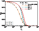
The time step is divided into 90 segments uniformly by the time of each order of magnitude (e.g., the time step is when between and ). The grid of the model is uniform, and the grid size is (0.25m) × (0.25m) (Fig. 2(a)). Three positions (i.e., Point 1 at , Point 2 at and Point 3 at ) of the excess pore pressure are selected to compare the FDM solution and the analytical solution. As shown in Fig. 2(b), the proposed solution coincides with the FDM solution almost completely, which indicates the correctness of the proposed solution.
(a) (b)
4. Results and Discussion
For convenience of analysis, the time factor, , and the dimensionless excess pore pressure, are defined as follows
|
|
(40) |
4.1 Parameter analysis
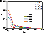
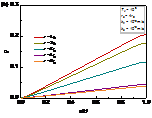
Fig. 3(a) illustrates the distribution of excess pore pressure along the depth. The excess pore pressure increases with the increase in depth. After consolidation for a period of time (i.e., ), the excess pore pressure at different depths in the disturbed zone was still higher than that in the undisturbed zone (i.e., ). Fig. 3(b) shows that the excess pore pressure increases linearly with depth direction under different r. The growth rate of the excess pore pressure with depth is large in the disturbed zone (i.e., ), while the growth rate of the excess pore pressure with depth is small in the undisturbed zone (i.e., ).
According to the research works proposed by Li et al. (2017) [9], time-dependent bearing capacity is mainly affected by the dissipation of the excess pore pressure at the pile-soil interface. In order to study the influence of the soil disturbance induced by pile installation on the excess pore pressure at pile-soil interface, this paper introduces the dimensionless average excess pore pressure at pile-soil interface ( ) for analysis:
|
|
(42) |
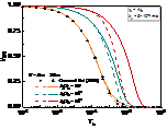
In Fig. 4, the influence of permeability coefficient ratio on the excess pore pressure under deep and shallow foundations, where reflects the disturbance degree of pile installation. When , this solution can degenerate into the solution of homogeneous soil around a pile [12]. Whether it's Case of shallow foundation (i.e., Case of ) or Case of deep foundation (i.e., Case of ), the dissipation rate of the excess pore pressure gradually decreases with decreases in , which indicates that could be overestimated at the anytime without considering the disturbance effect. The dissipation rate of the average excess pore pressure at pile-soil interface decreases obviously with the increase of , which indicated that soil disturbance has a significant hindering effect on . By comparing Case of shallow foundation and Case of deep foundation, it is clearly known that the disturbance effect has a greater influence on deep foundation than on shallow foundation. Moreover, the difference of drainage performance of deep and shallow foundations is gradually obvious with the increase of .
Unlike which reflect the degree of disturbance, the radius of the disturbed zone, , reflects the disturbance range. The impact of on the excess pore pressure is introduced in Fig. 5. This solution can degenerate into the solution of homogeneous soil around a pile when [12]. Additionally, compared with the case without disturbed zone (i.e., ), the dissipation rate of decreases gradually with the increase of in the intermediate and later stages. Moreover, it is found that the consolidation rate of the deep foundation is smaller than that of the shallow foundation with the increase of .
4.2 Test analysis
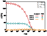
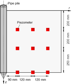
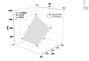
To demonstrate the validity of the proposed solution, a set of published laboratory test data is used for comparison [31]. As shown in Figure 6 (a), the test box is a cube with a side length of 1000 mm, and the test pile is a PVC pipe with a radius of 30 mm and length of 900 mm (length of 700 mm in the soil). The literature suggests that re is equal to 20 times r0 [31]. Because the Piezometer 1 ~ 3 (i.e., P1 ~ P3, at distance of r = 90 mm) are close to the pile, the measurement data fluctuates greatly, so only the data of P4 ~ P9 are used for analysis. P4 ~P6 are located at distance of r = 210 mm and P7 ~ P9 are located at distance of r = 330 mm. According to the initial excess pore pressures of P4 ~ P9, the parameters of the initial excess pore pressure is determined as shown in Fig. 6 (b).
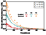
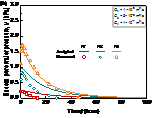
The calculated and measured values of the excess pore pressure are shown in Figure 7. It is observed that the calculated value is a good fit with the measured value. That indicates the proposed mathematical model has a good ability to predict the variation trend of the excess pore pressure.
5. Conclusions
In this paper, an analytical solution to consolidation problem with disturbance effect in the soil around a pile is derived and its accuracy is verified by degradation analysis and the FDM. The influence of disturbance effect on the excess pore pressure dissipation of the soil around a pile under long and short foundation is analyzed. It was concluded that the excess pore pressure in the disturbed zone is more difficult to dissipate than that in the undisturbed zone; The dissipation rate of the average excess pore pressure gradually decreased obviously with the increase of permeability coefficient ratio, , on the whole dissipation period at pile-soil interface; The impact of radius ratio, , on the excess pore pressure is interesting. When is small, only impedes dissipation rate of excess pore pressure in the early and intermediate dissipation periods. But, with increases, can impedes dissipation rate of excess pore pressure on the whole dissipation period. Disturbance effect (e.g., and ) has obvious negative effect on both shallow and deep foundation, and the negative effect on deep foundations is greater than that on shallow foundation. Finally, the proposed solution is used to predict a test case, which shows that the proposed solution has a good ability to predict the variation trend of the excess pore pressure. However, this model only assumes that the soil is elastic and ignores the effect of the external load, which will be the objective of subsequent research.
Author Contributions
Conceptualization: Ping Li; writing—original draft preparation: Ping Li and Zhijian Chen; writing—review and editing: Yi Ding.
Institutional Review Board Statement
This study did not require ethical approval.
Informed Consent Statement
Not applicable.
Data Availability Statement
All data, models, and code generated or used during the study appear in the submitted article.
Conflict of Interest
The authors declared that they have no conflicts of interest to this work.
References
[1] K T Tran, M McVay, R Herrera, P Lai. A new method for estimating driven pile static skin friction with instrumentation at the top and bottom of the pile. Soil Dynamics and Earthquake Engineering. 2011;31(9):1285-1295.
[2] M E Mabsout, J L Tassoulas. A finite element model for the simulation of pile driving. International Journal for Numerical Methods in Engineering. 1994;37(2):257-278.
[3] J H Hwang, N Liang, C H Chen. Ground response during pile driving. Journal of Geotechnical and Geoenvironmental Engineering. 2001;127(11):939-949.
[4] M Y Fattah, W H Al-Soudani, M Omar. Estimation of bearing capacity of open-ended model piles in sand. Arabian Journal of Geosciences. 2016;9(3):1-14.
[5] Pantea Azimi, M Karimpour-Fard, N Shariatmadari, C Tsuha. A new approach to estimate the bearing capacity of driven piles. Arabian Journal of Geosciences. 2021;14(13):1-12.
[6] M R Mahmood, S J A Qadir. Effect of particle size distribution of cohesionless soils on the ultimate carrying capacity of open ended pipe piles under different saturation conditions. Arabian Journal of Geosciences. 2018;11(21):1-15.
[7] J Dijkstra, W Broere, O M Heeres. Numerical simulation of pile installation. Computers and Geotechnics. 2011;38(5):612-622.
[8] X T Xu, H L Liu, B M Lehane. Pipe pile installation effects in soft clay. Proceedings of the Institution of Civil Engineers-Geotechnical Engineering. 2006;159(4):285-296.
[9] L Li, J P Li, D A Sun, L X Zhang. Time-dependent bearing capacity of a jacked pile: An analytical approach based on effective stress method. Ocean Engineering. 2017;143:177-185.
[10] M F Randolph, C P Wroth. An analytical solution for the consolidation around a driven pile. International Journal for Numerical Analytical Methods in Geomechanics. 1979;3(3):217-229.
[11] W D Guo. Visco-elastic consolidation subsequent to pile installation. Computers and Geotechnics. 2000;26(2):113-144.
[12] Z K Gao, J Y Shi. Consolidation solution of soil around single-pile after pile sinking. Rock and Soil Mechanics. 2008;29(4):979-982.
[13] S H Wang, P P Ni, Z Chen, G X Mei. Consolidation solution of soil around a permeable pipe pile. Marine Georesources Geotechnology. 2019:1-9.
[14] Z Chen, T Xiao, J X Feng, P P Ni, D Q Chen, G X Mei, Y F Chen. Mathematical characterization of pile-soil interface boundary for consolidation analysis of soil around permeable pipe pile. Canadian Geotechnical Journal. 2020(ja).
[15] M Bozozuk, B H Fellenius, L Samson. Soil disturbance from pile driving in sensitive clay. Canadian Geotechnical Journal. 1978;15(3):346-361.
[16] T Fang, M Huang, K Tang. Cross-section piles in transparent soil under different dimensional conditions subjected to vertical load: an experimental study. Arabian Journal of Geosciences. 2020;13(21):1-8.
[17] K R Massarsch, C Wersäll. Cumulative lateral soil displacement due to pile driving in soft clay. Sound Geotechnical Research to Practice: Honoring Robert D. Holtz II; 2013: 462-479.
[18] Z Y Li, K H Wang, W B Wu, C J Leo, N Wang. Vertical vibration of a large-diameter pipe pile considering the radial inhomogeneity of soil caused by the construction disturbance effect. Computers and Geotechnics. 2017;85:90-102.
[19] Y Zhou, J C Chai. Equivalent ‘smear’effect due to non-uniform consolidation surrounding a PVD. Géotechnique. 2017;67(5):410-419.
[20] R Nazir, H Moayedi, P Subramaniam, S Ghareh. Ground improvement using SPVD and RPE. Arabian Journal of Geosciences. 2017;10(23):1-21.
[21] R D Holtz, M B Jamiolkowski, R Lancellotta, R Pedroni. Prefabricated vertical drains: design and performance; 1991.
[22] J Wang, Y L Yang, H T Fu, Y Q Cai, X Q Hu, X M Lou, Y W Jin. Improving consolidation of dredged slurry by vacuum preloading using prefabricated vertical drains (PVDs) with varying filter pore sizes. Canadian Geotechnical Journal. 2020;57(2):294-303.
[23] Y B Deng, G B Liu, B Indraratna, C Rujikiatkamjorn, K H Xie. Model test and theoretical analysis for soft soil foundations improved by prefabricated vertical drains. International Journal of Geomechanics. 2017;17(1):04016045.
[24] Z Chen, P P Ni, G X Mei, Y F Chen. Semi-analytical solution for consolidation of ground with partially penetrating PVDs under the free-strain condition. Journal of Engineering Mechanics. 2020;147(2):04020148.
[25] Y Tian, W B Wu, G S Jiang, M H El Naggar, G X Mei, P P Ni. Analytical solutions for vacuum preloading consolidation with prefabricated vertical drain based on elliptical cylinder model. Computers Geotechnics. 2019;116:103202.
[26] L O Soderberg. Consolidation theory applied to foundation pile time effects. Géotechnique. 1962;12(3):217-225.
[27] Z L Luo, F H Dong. Statistical investigation of bearing capacity of pile foundation based on Bayesian reliability theory. Advances in Civil Engineering. 2019;2019.
[28] B M Lehane, D R Gill. Displacement fields induced by penetrometer installation in an artificial soil. International Journal of Physical Modelling in Geotechnics. 2004;4(1):25-36.
[29] H de Chaunac, A Holeyman. Numerical analysis of the set-up around the shaft of a closed-ended pile driven in clay. Géotechnique. 2018;68(4):332-344.
[30] Q M Chen, M N Haque, M Abu-Farsakh, B A Fernandez. Field investigation of pile setup in mixed soil. Geotechnical Testing Journal. 2014;37(2):268-281.
[31] P P Ni, S Mangalathu, G X Mei, Y L Zhao. Laboratory investigation of pore pressure dissipation in clay around permeable piles. Canadian Geotechnical Journal. 2018;55(9):1257-1267.
Document information
Published on 17/03/22
Accepted on 06/03/22
Submitted on 04/11/21
Volume 38, Issue 1, 2022
DOI: 10.23967/j.rimni.2022.03.008
Licence: CC BY-NC-SA license
Share this document
Keywords
claim authorship
Are you one of the authors of this document?


