Abstract
Taking the double-layer water injection well and one graded water distributor could regulate two layers as the design and research goal, the sliding double-layer water injection distributor was designed by using the forward and reverse rotation of the driving motor to control the opening and closing of the two nozzles. The flow field of the two flow channels under different opening was analyzed by FLUENT software. The research shows that when the opening of the nozzle was less than 10mm, the maximum flow rate decreases rapidly, and when the opening exceeds 10mm, it decreases slowly. The mathematical models of flow pressure, flow velocity, and nozzle opening were obtained by data analysis and fitting. Finally, the kinematics simulation was carried out by AAMS, and the maximum friction force borne by each sealing in the movement process was obtained. The maximum torque borne in the movement process was 120.5N·m, which was less than the rated torque. The supporting motor could meet the design requirements.
Keywords: Reservoir water injection, water distributor, flow field analysis, dynamic analysis
1. Introduction
With the exploitation of the oilfield, the oil content in the formation is decreasing, which leads to a significant reduction in the formation pressure. Therefore, it is necessary to continuously inject water underground to supplement the missing pressure in the formation. In the process of oil production, in case of complex formation structure, layered water injection needs to be used to alleviate the contradiction between layers. The function of packer is to separate each production layer, while the water distributor is to control the water injection between layers and ensure the stability of oil production [1]. Aiming at the existing double-layer water injection wells in the oilfield, a set of single motor-controlled water distributor is designed to achieve the effect of completing two-layer water injection at one time. At present, layered water injection technology has been continuously improved in oilfield production. Wuqi oil production plant adopts the general water injection process, only a few adopt the layered water injection process, and the layered water injection adopts three processes: Eccentric water distribution, oil jacket separate injection and concentric separate injection [2]. In 2015, the integrated water distributor of measurement and regulation was designed in Shengli Oilfield, mainly including the accurate down to the oil layer to be injected and the regulation of water injection flow. The conventional concentric adjustable water distributor, large differential pressure concentric adjustable water distributor and non open concentric adjustable water distributor were designed to meet the needs of layered water injection in Shengli Oilfield [3,4]. The water injection technologies used in Daqing Oilfield mainly include conventional eccentric water injection technology, bridge eccentric layered water injection technology and concentric integral subdivision water injection technology [5]. Although the concentric integrated subdivision water injection process can achieve the purpose of subdivision [6], the application scope of the process is only four layers of water injection layer, and due to the large outer diameter of the water distribution plug, it will be difficult to salvage when the water quality is poor and the scaling is serious. The water distributor and packer not only play the role of stratification, but also play the role of the working cylinder of the integral water separator [7,8]. In 2019, after years of research and exploration in Shengli Oilfield, the layered water injection process in offshore oilfield is becoming more and more mature and perfect. The supporting tools are applicable to a variety of separate injection process technologies in different reservoirs and well bore structures. In summary, they can be divided into the following types: anchor compensation measurement and adjustment, anti-creep measurement and adjustment, concentric double pipes, hydraulic control measurement and adjustment and high inclination new measurement and adjustment [9,10]. This paper studies and designs a water distributor driven by a single motor to realize double-layer water injection, which is applied to the double-layer water injection well in the oilfield, and further analyzes the performance of the downhole water distributor structure.
2. Structural design of double-layer water injection distributor
In the design process, considering the sealing conditions between the two water nozzles, the distance between the two water nozzles is set, and considering the through-hole sealing, four-layer sealing is adopted, the sealing and the slide rod group constitute the slide rod assembly. The internal main body of the water distributor is designed and shown in Figures 1 and 2.
The diameter of the injection well is 120 mm, the daily water injection volume is 500 cubic meters, and the external pressure is 10 MPa. In order to meet the structure and size of the internal instrument, the position of the central pipe is shifted to form an eccentric flow channel. The main size is determined according to the diameter of the injection well and the technological requirements, which is shown in Table 1.
| Name | Size | |
|---|---|---|
| Diameter of outer protective sleeve | 120 mm | |
| First channel diameter | 30 mm | |
| Second channel diameter | 20 mm | |
| Sprue diameter | 45 mm | |
| Nozzle size | long 24 mm | wide 10 mm |
| Nozzle spacing | 50 mm | |
As shown in Figure 3, when the injected fluid is transported from ground to the main channel of the eccentric pipe, the ground control motor drives the screw to rotate forward, and the sliding assembly is threaded with the lead-screw. In this case, it starts to move to the left along the direction of the lead-screw, the first channel is slowly opened, the injected liquid enters the first channel through the flow channel, and leads to the formation through the connecting pipe of the first channel. The first layer of water injection is completed.

|
| 1-Roller screw; 2-Sliding component; 3-First crossing; 4-First channel take over |
| Figure 3. Working drawing of the first channel |
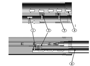
As shown in Figure 4, when the motor is reversed, the first crossing is closed and the second crossing is slowly opened. At this time, the injected liquid enters the second channel pipe from the second channel crossing through the drainage channel, and then leads to the next formation from the second channel connecting pipe to complete water injection. The water nozzle can automatically adjust the opening of the water nozzle according to the change of downhole flow. The pressure difference between the two pressure sensors is used to calculate the water distribution volume and detect and control the downhole flow in real time.
|
| 1-Second channel drainage port; 2-Second crossing; 3-First crossing; 4-Main channel; 5-Second channel nozzle |
| Figure 4. Working diagram of second channel |
3. Fluent fluid simulation analysis of adjustable nozzle of downhole water distributor
The junction of nozzle and runner is a relatively weak part. Because the fluid flow field at the junction of nozzle and runner will change, it is easy to produce serious scouring phenomenon. Reasonable pipe size design can predict the flow conditions under different pipe diameters [4], so relevant research is carried out.
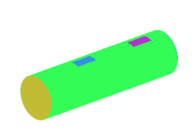
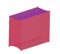
In the fluid simulation, because the flow channel model is very complex, it is very difficult to divide the mesh as a whole. Therefore, in the mesh division, each part is taken out separately for division, and then imported into FLUENT for connection to form a complete fluid diagram. The mesh quality of each part is controlled above 0.6, but proceeding on the opening position needs special attention. Therefore, the mesh quality is guaranteed above 0.8. The ICME mesh quality inspection is specifically used. The (Determinant) determinant check is calculated by calculating the Jacobian determinant value of each hexahedron and then standardizing the determinant matrix to characterize the deformation of the unit. The value of 1 indicates the ideal hexahedron cube and 0 indicates the anti-cube with negative volume. The closer the mesh quality is to 1, the better the mesh quality test result is, which is shown in Figure 5. According to the actual flow data, the inlet velocity of the flow field is 0.89 m/s and the outlet pressure is 10 MPa. In the simulation, water is selected as the fluid medium, and the material properties are defined as, density 1000 kg/m3, viscosity 0.001 pa·s.
 |
 |
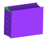 |
| (a) Mesh generation of main channel | (b) The opening of main channel and control channel | |
| Figure 5. Mesh quality of main road parts | ||
In the fluid simulation results, judged whether the fluent analysis converges according to the residual value detected and whether the mass, momentum and energy of the incoming and outgoing fluid are conserved in the flux reports dialog box.
3.1 First channel velocity analysis
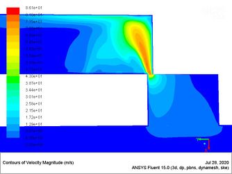
For the first channel, the fluid enters from the main channel, the water nozzle is slowly opened under the drive of the motor, and enters the water injection layer through the external connecting pipe. With the increase of nozzle opening, the maximum velocity at the nozzle decreases. Through the simulation of the internal flow field of the water distributor under different opening degrees, the distribution of the flow velocity in the fluid under the same flow rate is analyzed, and the nozzle size is selected as 2-24mm, with an interval of 2mm for 12 groups of simulation. The simulation results of the first group and the last group are shown in Figure 6, and the overall data are shown in Table 2.
| (a) Velocity chart of opening 2 mm | (b) Velocity chart of opening 24 mm |
| Figure 6. First channel velocity chart | |
As shown in Figure 6, the fluid enters the first channel through the lower main channel, and at the same time, it has the maximum velocity at the inlet. For different openings, the maximum velocity changes obviously. Therefore, the maximum velocity is selected as the research object of flow velocity, so as to reflect the working state of the water distributor according to the maximum velocity.
| Opening | Maximum velocity | Eddy current velocity | Outlet velocity |
|---|---|---|---|
| 2 mm | 86.1 m/s | 17.2 m/s | 4.3 m/s |
| 4 mm | 48.7 m/s | 12.18 m/s | 3.825 m/s |
| 6 mm | 34.2 m/s | 5.12 m/s | 3.418 m/s |
| 8 mm | 25.6 m/s | 3.84 m/s | 5.12 m/s |
| 10 mm | 20.5 m/s | 3.07 m/s | 5.12 m/s |
| 12 mm | 20.49 m/s | 3.07 m/s | 5.12 m/s |
| 14 mm | 14.5 m/s | 2.16 m/s | 5.05 m/s |
| 16 mm | 12.1 m/s | 2.13 m/s | 4.83 m/s |
| 18 mm | 10.6 m/s | 2.12 m/s | 4.78 m/s |
| 20 mm | 10.1 m/s | 2.02 m/s | 4.54 m/s |
| 22 mm | 8.99 m/s | 1.34 m/s | 4.49 m/s |
| 4 mm | 8.64 m/s | 0.86 m/s | 4.31 m/s |
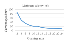
It can be seen from the simulation data in the table that the flow velocity at the vortex on the right is much less than the inlet flow velocity, which has little impact on the overall kinetic energy, so it has little impact on the fluid simulation results. According to the simulation data, the curve under the change of maximum flow velocity with opening is drawn, shown in Figure 7.
|
| Figure 7. Flow velocity curve of the first channel |
The simulation data is fitted by Origin software, and the change law is shown in Eq. (1).
|
|
(1) |
where, represents flow velocity, m/s; represents opening, mm.
3.2 Second channel velocity analysis
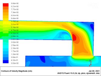
For the second channel, similar to the first channel, the nozzle is slowly opened by motor drive. The internal flow field of water distributor under different opening is simulated, and the internal velocity distribution under the same flow and different opening is analyzed, shown in Table 3. The analysis results of 6mm and 16mm opening are shown in Figure 8.
| Opening | Maximum velocity | Eddy current velocity | Outlet velocity |
|---|---|---|---|
| 2 mm | 94.3m/s | 80.121 m/s | 18.9 m/s |
| 4 mm | 50.7 m/s | 46.508 m/s | 10.3 m/s |
| 6 mm | 34.7 m/s | 33.111 m/s | 9.2 m/s |
| 8 mm | 30.4 m/s | 28.9 m/s | 7.6 m/s |
| 10 mm | 27.2 m/s | 25.729 m/s | 6.81 m/s |
| 12 mm | 25.2 m/s | 23.929 m/s | 6.36 m/s |
| 14 mm | 24.3 m/s | 23.542 m/s | 6.22 m/s |
| 16 mm | 23.96 m/s | 22.312 m/s | 5.97 m/s |
| 18 mm | 23.5 m/s | 22.155 m/s | 5.68 m/s |
| 20 mm | 23.23 m/s | 21.521 m/s | 5.15 m/s |
| 22 mm | 22.86 m/s | 21.426 m/s | 5.02 m/s |
| 24 mm | 22.55 m/s | 21.32 m/s | 4.13 m/s |
| (a) Velocity chart of opening 6 mm | (b) Velocity chart of opening 16 mm |
| Figure 8. Second channelvelocity chart | |
As shown in Figure 8, the fluid enters the upper drainage channel through the lower mainstream channel. Because in the working process the fluid flows from the main channel to the second channel through the drainage channel, and in the structure, the second channel and the drainage channel remain completely connected during the conduction of the second channel, the inlet opening between the main channel and the second channel is simulated and analyzed by studying the opening between the main channel and the drainage channel. on the basis of the simulation results, the maximum velocity of the fluid still appears at the opening, and the response of the maximum velocity to different openings is still obvious, so the maximum velocity is used to study the working state of the water distributor.
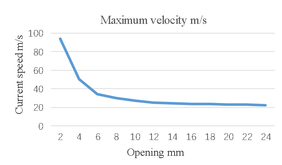
According to the simulation results of 12 groups, with the increase of opening, the maximum velocity decreases rapidly before 10mm, and the velocity decreases slowly when the opening exceeds 10mm. The flow rate curve under different openings is drawn, as shown in Figure 9.
|
| Figure 9. Flow velocity curve of the second channel |
Similarly, the curve equation is fitted to obtain the change law between the opening of the second channel and the flow rate, shown in Eq. (2)
|
|
(2) |
Compared with the first channel, the overall flow of the second channel is higher because the design outlet of the second channel is small and the fluid needs to pass through the drainage channel. Because the flow layer and pressure are different, the deeper the water injection well, the greater the pressure. Therefore, it is suitable for water injection in the middle and deep layers of double layers.
3.3 Fluid pressure distribution in the first channel
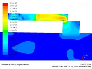
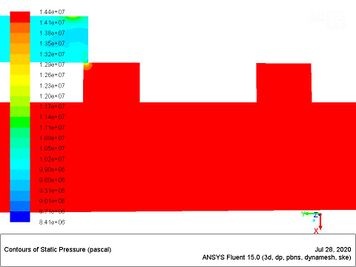
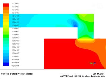
Under the same inlet velocity, the internal flow field under different nozzle openings is simulated, and 12 groups of flow pressure analysis results are obtained, shown in Table 4. The simulation results of 2mm and 24mm openings are shown in Figure 10.
| Opening | Maximum flow pressure | Outlet flow pressure |
|---|---|---|
| 2mm | 14.4MPa | 10.2006MPa |
| 4mm | 12.1MPa | 10.1069MPa |
| 6mm | 10.6MPa | 10.0025MPa |
| 8mm | 10.3MPa | 10.0112MPa |
| 10mm | 10.2MPa | 10.0042MPa |
| 12mm | 10.194MPa | 10.0041MPa |
| 14mm | 10.126MPa | 10.0004MPa |
| 16mm | 10.085MPa | 10.0043MPa |
| 18mm | 10.073MPa | 10.0003MPa |
| 20mm | 10.065MPa | 10.003MPa |
| 22mm | 10.054MPa | 10.0003MPa |
| 24mm | 10.048MPa | 10.0008MPa |
| (a) Opening 2 mm flow pressure diagram | (b) Opening 24mm flow pressure diagram |
| Figure 10. First channel flow pressure diagram | |
According to Figure 10, with the change of the opening of the main channel and the first channel, the maximum flow pressure changes more obviously, and the maximum flow pressure can be obtained directly from the internal pressure sensor of the main channel, and the maximum flow pressure is also used as the boundary condition of the subsequent ADAMS kinematics simulation analysis. Therefore, the research on the flow pressure takes the maximum flow pressure as the object and analyzes the relationship between the opening and the flow pressure.
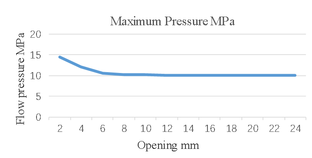
According to Table 4, it can be seen that the flow pressure decreases with the increase of opening. The change curve of flow rate under different opening conditions is drawn according to the data, shown in Figure 11.
|
| Figure 11. Flow pressure curve of the first channel |
According to the curve, the flow pressure drops rapidly when the opening is less than 6mm, and tends to be flat after it exceeds 6mm. The equation fitting is carried out with the simulation data of Origin software, and the change law is shown in Eq. (3)
|
|
(3) |
where, represents flow pressure, MPa, and represents opening, mm.
The fluid simulation analysis of the first channel is carried out, and the functional relationship between the flow pressure and the opening under different opening degrees is obtained. It can adjust different opening degrees through the pressure sensor, so as to achieve the required pressure of the water distributor, carry out real-time control and adjust the opening of the water nozzle, realize the water flow adjustment under different pressures, and complete balanced water injection.
3.4 Fluid pressure distribution in the second channel
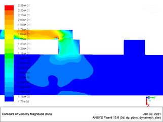
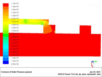
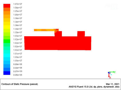
The same method is used to simulate the second channel and observe the pressure distribution of the fluid in the pipeline. The calculation results are shown in Table 5, and the analysis results of 10mm and 14mm openings are shown in Figure 12.
| Opening | Maximum flow pressure | Outlet flow pressure |
|---|---|---|
| 2mm | 15.8MPa | 10.104MPa |
| 4mm | 11.7MPa | 10.080MPa |
| 6mm | 11.2MPa | 10.058MPa |
| 8mm | 11.0MPa | 10.049MPa |
| 10mm | 10.82MPa | 10.033MPa |
| 12mm | 10.8MPa | 10.039MPa |
| 14mm | 10.7MPa | 10.021MPa |
| 16mm | 10.625MPa | 10.015MPa |
| 18mm | 10.537MPa | 10.014MPa |
| 20mm | 10.51MPa | 10.013MPa |
| 22mm | 10.492MPa | 10.021MPa |
| 24mm | 10.41MPa | 10.011MPa |
| (a) Opening 10mm flow pressure diagram | (b) Opening 14mm flow pressure diagram |
| Figure 12. Second channel flow pressure diagram | |
According to Figure 12, the flow pressure between the main channel and the drainage channel is used to study the flow pressure change between the main channel and the second channel. Similar to the flow pressure analysis of the first channel, the relationship between the flow pressure and the opening is studied with the maximum flow pressure as the object.
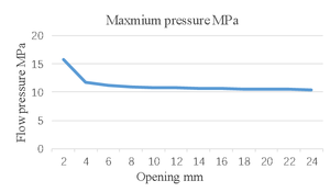
With the increase of the nozzle opening, the pressure of the fluid in the pipe at the same position decreases continuously, and the internal flow pressure of the second channel is higher than that of the first channel. Since the outlet pipe diameter of the second channel is smaller than that of the first channel, and the second channel must pass through the drainage channel, the flow pressure change curve under different openings is drawn according to the data, shown in Figure 13.
|
| Figure 13. Flow pressure curve of the second channel |
It can be seen from the flow pressure curve that the opening is within 4mm. With the increase of opening, the pressure drops fast. After exceeding 4mm, the flow pressure drops slowly. The simulation data of Origin software is used for fitting, and the change law is shown in Eq. (4)
|
|
(4) |
The fluid simulation analysis of each channel is carried out, and the mathematical models between flow velocity, flow pressure and opening under different opening are obtained. According to each model, the operation status of the water distributor can be judged in the work, and the conditions for subsequent ADAMS dynamic simulation are provided.
4. Dynamic simulation analysis of water distributor
During the opening adjustment of the water distributor, friction force will be generated between the sealinging and the sliding sleeve. The motion process is simulated by ADAMS to analyze the torque overcome by the motor, complete the motor selection and verify the rationality of the structural design.
ADAMS software provides a variety of definition methods of motion pairs, which can truly simulate the motion process of mechanical system. This system involves 12 components. In order to achieve the required motion, the added motion pairs are shown in Table 6.
| Component 1 | Component 2 | Constraint relation |
|---|---|---|
| Sliding sleeve | Earth | Fixed pair |
| Key | Earth | Fixed pair |
| Screw | Earth | Rotating pair |
| Slide rod | Sliding sleeve | Moving pair |
| Screw | Slide rod | Screw pair |
| Screw | Earth | Cylindrical pair |
| Sealinging element | Slide rod | Hu Ke pair |
| Sealinging element | Sliding sleeve | Moving pair |
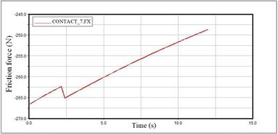
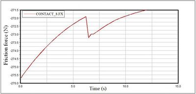
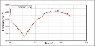
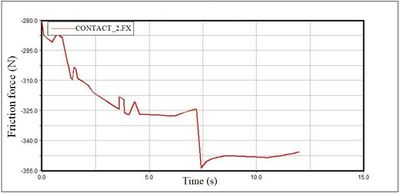
Because the motor needs sealing protection, there is a sealing design between the screw and the motor. As shown in Figure 14, there is a pressing plate on the screw to press the sealing sleeve tightly, and the sealing sleeve and the screw are isolated from the contact between the fluid and the motor. Through fluid simulation analysis, it can be seen that the internal pressure of the first-class channel is calculated according to the maximum value of 15 MPa. The static friction force and dynamic friction force between the pressing plate and the sealing sleeve are calculated to be 1231 N and 678 N respectively. The ADAMS simulation analysis of the first channel is carried out, and the friction between each seal and the sliding sleeve is obtained by simulation, as shown in Figures 15 16. It can be seen from the figure that as the sliding component moves, the friction between the seal and the sliding sleeve changes continuously in one cycle. The relevant data collation is shown in Tables 7 and 8.

|
| 1-nut; 2-compression plate; 3-sliding rod contact thread |
| Figure 14. Planetary roller screw |
|
|
| Figure 15. Friction curve of small sealing | |
|
|
| Figure 16. Friction curve of large sealing | |
| Sealing No | Maximum | Minimum | Average value |
|---|---|---|---|
| 1 | 280N | 223N | 250N |
| 2 | 276N | 257N | 265N |
| 3 | 266N | 248N | 258N |
| 4 | 230N | 200N | 212N |
| Sealing No | Maximum | Minimum | Average value |
|---|---|---|---|
| 1 | 354N | 280N | 325N |
| 2 | 360N | 322N | 335N |
| 3 | 317N | 301N | 310N |
| 4 | 275N | 271N | 273N |
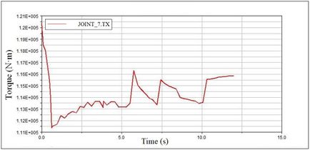
From the above data analysis, it can be seen that the friction generated by the sealing changes with the pressure and the contact surface. As the time when the four sealingings generate the maximum friction is different during the movement of the sealing, considering the extreme working conditions, the maximum friction generated by each sealing is combined as the basis for selecting the motor. The sum of the dynamic friction calculated according to Tables 7 and 8 is 3306 N, the maximum friction obtained is substituted into Adams components as a known condition, and the external load is re-established to simulate the torque required by the motor, shown in Figure 17.
|
| Figure 17. Motor torque curve |
As shown in Figure 17, the maximum torque is 120.5N•m. According to the torque power function, the power of the motor is about 1.5KW, which is less than the rated power of the selected motor 2KW, meeting the design requirements.
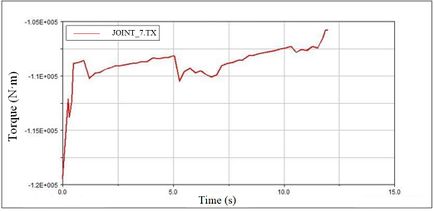
The ADAMS simulation analysis of the second channel is carried out in the same way. Through the simulation analysis, the friction between each sealing and the sliding sleeve is obtained, and the relevant data is extracted to calculate that the sum of dynamic friction is 2966N.
By using the same method, shown in Figure 18, the maximum torque of the reverse motor is 120N•m, and the corresponding required power is about 1.5KW, which is less than the rated power 2KW, meeting the production requirements of the oilfield.
|
| Figure 18. Motor torque diagram |
5. Conclusions
Aiming at the design and research of double-layer water injection well and one graded water distributor, a set of single motor-driven water distributor is designed to realize underground two-layer water injection, and the key structures of the water distributor are simulated by fluid and dynamics. The main research conclusions are as follows:
1. For the double-layer water injection well with a diameter of 120mm and an injection volume of 500 m3 per day, a double-layer water injection well is designed, which uses the forward and reverse rotation of the motor to control the opening and closing of the two water nozzles. The designed water nozzle size is 24mm, the spacing between the two water nozzles is 50mm, four sealingings are adopted, and the diameters of the two flow channels are 30mm and 20mm respectively. Owing to the limitation of water injection well and the size of accessories, the eccentric pipe string is used to complete the overall structural design of water distributor.
2. FLUENT software is used to simulate the flow field of the two flow channels under different nozzle opening. The analysis shows that when the nozzle opening is less than 10mm, the maximum flow rate decreases rapidly, and then decreases slowly after exceeding 10mm. The mathematical model between flow pressure, flow velocity and nozzle opening is obtained by fitting, which provides a basis for subsequent research.
3. The kinematics simulation is carried out by using ADAMS software. The analysis shows that the sliding rod drives the sealing to slide in the sliding sleeve. The friction force of each sealing is 120.5N•m, the maximum torque limit is 120.5N•m, and the motor power required by the corresponding motor is 1.5KW, which is less than the rated power 2KW, meeting the design requirements.
Acknowledgement
This research is supported by China University of Petroleum (East China).
References
[1] Chen H. Simulation and structural optimization of packer for layered water injection. China University of Petroleum (East China), 2017.
[2] Wang C. Analysis on present situation of layered water injection process in Wuqi oil production plant. China Petroleum and Chemical Industry standards and Quality, 38(24):160-161, 2018.
[3] Li C. New progress of layered water injection technology integrating measurement and regulation in Shengli Oilfield. Petroleum Machinery, 43(6):66-70, 2015.
[4] Dang L. Research on downhole multifunctional water injection tool. Sino Foreign Energy, 23(04):54-57, 2018.
[5] Xu W. Practical application analysis of layered water injection technology in Oilfield. Chemical Engineering and Equipment, (04):86+49, 2019.
[6] Han W., Xu W. Design of a new downhole layered water injection tool. Inner Mongolia Petrochemical Industry, 40(04):81+89, 2014.
[7] Zhu Z. Research on bridge eccentric integrated water injection technology. Daqing Petroleum Institute, 2008.
[8] Liu Y., Wang Y., Yao C., Liu T., Wang Y. Analysis of external flow field of main nozzle based on ANSYS/fluent. Textile Equipment, 43(04):5-10, 2016.
[9] Mu J. Present situation and Prospect of layered water injection technology in Shengli Offshore Oilfield. Neijiang Technology, 40(05):34-35, 2019.
[10] Ju Y., Wang Z., Ma H., Chen W., Jinxiaohong G. Test and evaluation of intelligent testing and allocation technology for layered water injection wells. Oil and Gas Well Test, (06):51-52+56+74-75, 2006.Document information
Published on 15/11/22
Accepted on 03/11/22
Submitted on 08/06/22
Volume 38, Issue 4, 2022
DOI: 10.23967/j.rimni.2022.11.002
Licence: CC BY-NC-SA license
Share this document
claim authorship
Are you one of the authors of this document?


