Abstract: To address the contradiction between supply and demand of water resources in China, mitigate flood and drought disasters, develop sustainable hydropower resources, realize the transformation of the energy industry structure, and realize the Chinese dream of building a beautiful China, the construction of high dams and large reservoirs is imperative. The gates of such conservancy and hydropower structures play an important role in regulating water resources. Only through the flexible operation of gates can the high dams and large reservoirs be adjusted in real time to meet the needs of flood control, power generation, and water resource allocation. The safety of gates largely determines the security of the dams and the life and property of people residing downstream. Therefore, the safety design of gates is of utmost importance. This paper presents a comprehensive analysis of the status of development of water conservancy and hydropower engineering gates; material selection, connection methods, classification, selection, design of gates; as well as the design codes for gates in international engineering. This paper also elucidates the emerging trends related to materials, structures, connection methods, and design methods of gates.
Key points: Water resources; Hydropower resources; Energy structure; High dams and large reservoirs; Current situation and trend of gates
0 Introduction
Water resources are fundamental natural and strategic economic resources; with the rapid socioeconomic development in China, the availability of water resources has become a major challenge for sustainable development. China has extensive water resources, with more than 50,000 rivers within its borders, each covering a basin area of over 100 km2. The total annual precipitation is 618.89 billion m3; the average annual surface water resource is 2.7115 billion m3, while the average groundwater resource is 888.8 billion m3. Deducting redundant data, the average annual water resource is 281.2 billion m3(Zheng 2012). However, China’s vast territory and complex terrain makes it strongly sensitive to monsoon precipitation, and the distribution of precipitation is extremely unbalanced. In general, water resource distribution in north of China is considerably less compared with that in south of China. The four catchments of the Yangtze River, the Pearl River, the southeastern rivers, and the southwestern rivers in the south account for 36% and 54.4% of the country’s cultivated land and population, respectively. Water resources in the South account for 81% of that in the country. Precipitation is concentrated in the short rainy season, with usually 60%–70% of the annual rainfall occurring from June to September. Rainfall in the flood season accounts for 60%–80% and 80% of the annual rainfall in the South and North, respectively. The characteristics of water resources in China are uneven regional distribution, unbalanced land and water resources, concentrated distribution during the year, and large inter annual variation. Moreover, continuous wet and continuous dry years are prominent. Hence, China is prone to floods and droughts and thus experiences extremes in the supply and demand of water. These aspects have necessitated the arduous task of developing and utilizing sustainable water and hydropower resources in China.
Hydraulic engineering involves the control and deployment of surface water and groundwater in nature such that the associated merits are promoted and detriments are mitigated. The presence of water resources in the natural state is not adequate to fully meet the needs of humans; the construction of water conservancy projects is inevitable to control, regulate, and allocate water; develop and utilize water energy to meet the needs of the country’s economy; and maintain social sustainable development. In the 20th century, developed western countries entered the peak period of water conservancy and hydropower infrastructure construction; similar projects in China began to gradually progress after 1949. Hydropower does not consume the limited mineral resources, is recyclable, and is environment-friendly; in addition, hydropower stations and reservoirs can contribute to the local climate and environment. Before 1949, China’s hydropower installed capacity was merely 160 MW, and its annual power generation was only 700 million kWh. By 2017, China has ranked first in the world in this regard, with these values reaching 340 million kW and 1.1 trillion kWh, respectively. China is the world leader in both the theoretical potentiality and actual technological exploitation of hydropower resources. China holds about 1/6 of the world’s total hydropower resources; currently, only approximately 30% is being used, meaning that there is huge potential for development. The theoretical potentiality of the hydropower installed capacity is as high as 694,400 MW. In terms of the technological exploitation of hydropower resources, the three most prolific Chinese provinces (districts) are Sichuan (1200040 MW), Tibet (110004 MW), and Yunnan (101939 MW), accounting for 22%, 20%, and 19% of the nation’s technologically exploitable volume, respectively. The three highest levels of technological exploitation of river hydropower resources in China are in the Yangtze River Basin (256273 MW), Brahmaputra River Basin (67850 MW), and Yellow River Basin (37343 MW), which account for 47%, 13%, and 7% of the nation’s total technological exploitation, respectively.
To better solve the mismatch between supply and demand of water resources in China, mitigate flood and drought disasters, develop contained hydropower resources, realize the transformation of the energy industry structure, and realize the Chinese dream of building a beautiful China , the construction of high dams and large reservoirs is imperative, such as large-scale Gezhouba hydraulic engineering (1988),Longyangxia hydraulic engineering (1992), Tianshengqiao hydraulic engineering (1998), Xiaolangdi hydraulic engineering (2001), Three Gorgeshydraulic engineering (2006), Shuibuya hydraulic engineering (2007), Xiaowan hydraulic engineering (2010), Xiangjiaba hydraulic engineering (2014), Xiluodu hydraulic engineering (2015), and Baihetan hydraulic engineering (2022) (Liu et al. 2016). Gates of hydraulic engineering projects play an important role in regulating water resources. A gate, which is an important component of a hydraulic structure, fully or partially opens the orifices of the structure as required to regulate the upstream and downstream water levels, discharge flow, power station operation, navigation, and other control functions. Flexible operation of reservoir gates facilitates real-time flood control, power generation, and water resource allocation. Moreover, the safety of gates largely determines the security of the dams and the life and property of people residing downstream. Gates account for a large proportion of the total cost of hydraulic structures, generally accounting for 10%–30% and as high as 50% in some projects (Anhui Survey and Design Institute of Water Conservancy and Hydropower. 1980). Therefore, the safety design of gates is a critical task. This study focuses on the development of reservoir gates, material selection, connection methods, classification, selection, design process, design code for gates in international engineering and discusses the emerging trends related to research on large hydraulic gates.
1 Current situation of gates
With the rapid development of water conservancy and hydropower engineering projects, by the end of 2014, China had built more than 98000 reservoirs of various types, with a total storage capacity of 8.166 × 10¹¹ m3. Twenty super-high dams (height 200 m or taller) have been constructed or are under construction, of which two dams are over 300 m. China has the largest reservoirs and dams in the world (Department of Construction and Management of the Ministry of Water Resources. 2012; Wang et al. 2017). With the continued construction of high dams and large reservoirs and the continual improvement of the manufacturing level of metal structures, hydraulic gates tend to have higher water heads, larger orifices, and greater discharging capacity than ever before; consequently, the load and deadweight of the gates are continually increasing. The world’s largest gates are the Bureya hydropower Tainter gate, which is 63 × 17.5 m2 in size (He 1993); Xiluodu Tainter gate, which has a maximum weight of 702 tons; Inguri Tainter gate, which has a maximum head of 181 m; and Rotterdam new waterway tidal gate, which has a maximum span of 360 m. Table 1 summarizes details of the world’s large and high-head gates, and Table 2 summarizes the details of China’s large and high-head gates, most of which are located in the Southwest.
The first ship lock was built in the Cascades Canal, United States, in the 1880s. The first steel gate was constructed in the mid-1930s. The earliest known Tainter gates were four 8.75 m × 1.0 m (width × height) gates located on the Seine in Paris, built in the 1930s. In the United States, a three-curved-bar–type wooden Tainter gate was built in 1810, and a drive chain was installed to control the opening and closing of the upstream panel. A 12.0 m × 1.87 m (width × height) Tainter gate was built in Germany around 1895; around the same time, a document describing the use of radial gates on the Mississippi River was published in the United States. In 1976, about 28 Tainter gates were installed in Bavaria, Germany. Since then, reservoir gates have seen rapid development and widespread application and have been designed in various forms.
| No. | Engineering | Country | Gate name | Size of orifice
(water head, width × height-water head, m) |
Total water pressure(kN) | Gate type |
| 1 | Rotterdam New Channel | Netherlands | Tide lock | 360.0×22.0–17.0 | 700000 | Tainter gate |
| 2 | Tianshengtiao-I | China | Emergency gate | 6.8×9.0–120.0 | 73540 | Plane chain wheel |
| Service gate | 6.4×7.5–120.0 | 87350 | Tainter gate | |||
| 3 | Serre Poncon | France | Emergency gate | 6.2×11.0–124.0 | 84300 | Plane chain wheel |
| 4 | Laxiwa | China | Emergency gate | 4.0×9.0–132.0 | 48694 | Plane fixed wheel |
| Service gate | 4.0×6.0–132.0 | 46096 | Tainter gate | |||
| 5 | Jingping-I | China | Emergency gate | 5.0×12.0–133.0 | 87200 | Plane sliding gate |
| Service gate | 5.0×6.0–133.0 | 52120 | Tainter gate | |||
| 6 | Itaipu | Brazil
Paraguay |
Service gate | 6.7×22.0–140.0 | 190150 | Plane fixed wheel |
| 7 | Tarbela | Pakistan | Service gate | 4.1×13.7–141.0 | 75350 | Plane fixed wheel |
| 8 | Shuibuya | China | Emergency gate | 5.0×11.0–152.0 | 84530 | Plane fixed wheel |
| Service gate | 6.0×7.0–154.0 | 102200 | Tainter gate | |||
| 9 | Xiaowan | China | Emergency gate | 5.0×12.0–160.0 | 106300 | Plane chain wheel |
| Service gate | 5.0×7.0–163.0 | 110000 | Tainter gate | |||
| 10 | Enguri | Georgia | Bottom outlet | φ4.35–181.0 | 32560 | Paradox gate |
| No. | Engineering | Province | Gate name | Size of orifice
(width × height-water head, m) |
Total water pressure(kN) | Gate type |
| 1 | Longyangxia | Qinghai | Service gate | 5.0×7.0–120.0 | 42050 | Tainter gate |
| 2 | Dongjiang | Hu Nan | Service gate | 6.4×7.5–120.0 | 57670 | Tainter gate |
| 3 | Tianshengqiao-I | Gui Zhou | Emergency gate | 6.8×9.0–120.0 | 73540 | Plane chain wheel |
| Service gate | 6.4×7.5–120.0 | 87350 | Tainter gate | |||
| 4 | Nuozhadu | Yun Nan | Service gate | 5.0×8.5–126.0 | 84800 | Tainter gate |
| 5 | Pubugou | Si Chuan | Emergency gate | 7.0×9.0–124.0 | 84900 | Plane chain wheel |
| Service gate | 6.5×8.0–126.3 | 121870 | Tainter gate | |||
| 6 | Laxiwa | Qing Hai | Emergency gate | 4.0×9.0–132.0 | 48694 | Plane fixed wheel |
| Service gate | 4.0×6.0–132.0 | 46096 | Tainter gate | |||
| 7 | Jingping-I | Si Chuan | Emergency gate | 5.0×12.0–133.0 | 87200 | Plane sliding gate |
| Service gate | 5.0×6.0–133.0 | 52120 | Tainter gate | |||
| 8 | Xiaolangdi | He Nan | Service gate | 4.8×4.8–140.0 | 42130 | Tainter gate |
| 9 | Shuibuya | Hubei | Emergency gate | 5.0×11.0–152.0 | 84530 | Plane fixed wheel |
| Service gate | 6.0×7.0–154.0 | 102200 | Tainter gate | |||
| 10 | Xiaowan | Yun Nan | Emergency gate | 5.0×12.0–160.0 | 106300 | Plane chain wheel |
| Service gate | 5.0×7.0–163.0 | 110000 | Tainter gate |
2 Material selection and connection methods of gates
2.1 Material selection
The material used for gates of high dams and large reservoirs is mainly determined by the technology, economic conditions, and the importance of the gate at that time. With socioeconomic development, gate materials have also developed, from the initial wooden, cast-steel, cast-iron, and reinforced-concrete gates to modern steel gates. The specific principles underlying the determination of the material for a gate are as follows:
- 1) For a small orifice, the water head and the number of instances of gate opening and closing are low, so wood can be used as the gate material. However, wood has poor durability in water and would need to be replaced frequently. Therefore, wooden gates are no longer used.
- 2) For gates with a small orifice or a complex shape, cast steel or cast iron can be used; however, this material has disadvantages, including high labor requirement, casting process workload, and cost as well as susceptibility to corrosion when the gate is kept closed or open for a long time, when the gate is subject to abnormal operation of the hoisting equipment, and when the gate has low bending strength. The cast-steel or cast-iron gates are rarely used in present times.
- 3) Reinforced-concrete gates are no longer used due to their heavy weight, difficulty of opening and closing orifices, and low ability to achieve water sealing.
- 4) Steel gates possess advantages such as relatively high strength, stiffness, and stability; convenient processing; being light weight, which reduces the hoist capacity; effective sealing ability; and flexible operation. Moreover, the steel output is high in China. Therefore, all water conservancy and hydropower gates in China are made of steel. The cost of stainless steel is generally four to eight times that of carbon steel, so in engineering structures, stainless-steel gates are not used. However, with the continuous development of the economy and manufacturing technology, high-performance stainless steel can be considered in future. This paper [javascript:showjdsw('showjd_0','j_0') describe]s carbon steel gates (hereinafter, “steel gates”).
2.2 Connection methods
The process of connecting gates to a reservoir structure can be generally classified into four types: riveting, welding, casting, and mixed connection. Riveting gates were common before and after 1949, but because of the high consumption of steel, labor intensity, and manufacturing costs, this method has gradually been eliminated with the continuous improvement and popularization of welding technology. Welding is currently the main method of connecting steel gates. In the past, manual arc welding method was predominantly used; this approach is labor intensive and inefficient. With the development of welding technology, automatic welding has become more prevalent; this approach improves the quality of welding products and reduces production costs. Casting is a method suitable for small-orifice or complex-shaped gates. However, casting gates are generally expensive and entail high process difficulty and workload; hence, this approach is not used often. Mixed-connection steel gates may be more advantageous in cases where, for example, the gate needs to be installed under extremely low-temperature conditions, the field lacks proper protective measures, and welding does not guarantee quality. In such cases, welded gates with bolted joints can be used. In addition, for reinforcing or rebuilding existing gates while accounting for the effect of weight on the original structure, mixed connection can be used.
3 Classification and composition of gates
Per their function, gates can be classified into service gates, emergency gates, bulkhead gates, and construction diversion gates. A service gate is often used to adjust the flow through orifices and undertake the main work of the structure; it can be opened and closed under hydrodynamic action. An emergency gate can be closed during a hydrodynamic situation, such as when an accident occurs in the upstream or downstream facilities. A bulkhead gate can be opened and closed under hydrostatic action when the associated facilities need to be repaired. A construction diversion gate can close diversion holes under hydrodynamic action.
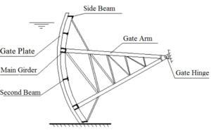
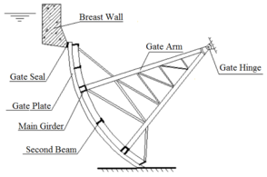
Per the position of the gate with respect to the orifice, gates can be classified into surface gates and submerged gates. For a surface gate, the upper edge of the gate panel is higher than the upstream water level, whereas for a submerged gate, the upper gate edge is lower than the upstream water level, as shown in Figures 1 and 2, respectively.
Per the design retaining water height of the gate, gates are classified into low-head gates (design retaining water height < 25 m), mid-head gates (25–50 m), high-head gates (50–80 m), and super-high-head gates (>80 m).
|
|
| Figure 1 Surface gate | Figure 2 Submerged gate |
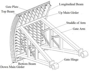
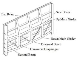
Per their structural feature, gates can be classified into Tainter gates, plane gates, and miter gates, as shown in Figures 3–5, respectively. The main components of a gate are as follows: 1) movable part: this structure adjusts the extent of orifice opening and is generally called the gate leaf; 2) gate buried part: this structure mainly refers to the part embedded in the civil engineering structure, and it transfers the load acting on the gate leaf; 3) hoisting equipment: it is the manipulation mechanism for controlling the position of the gate leaf in the orifice. The gate leaf consists of the following: i) gate faceplate: it closes the orifice and directly bears the water pressure; ii) frame: this structure, having sufficient strength and stiffness, supports the gate faceplate and transmits the water pressure from the faceplate to the supporting parts; iii) supporting-walking part: these components can pass the force transmitted from the frame to the structure and ensure a flexible and reliable movement of the gate leaf; iv) spreaders: these components are connected to the hoisting equipment; v) water seal: this component is used to block the gap between the gate leaf and the buried part, preventing leakage of water through the gate when the orifice is closed.
4 Basis for selection of gates
From the engineering perspective, the appropriate selection of gate type is a delicate and complex task that involves many determining factors. For the selection of the gate type, designers should consider not only the various requirements of the hydraulic structure and the gate but also the purpose and convenience of use as well as the available technology and economical rationality. In addition, the gate must complement the design of the entire hydraulic structure. The specific requirements are as follows: 1) The gate should meet all operational requirements of the structure; 2) the hydraulic conditions of the gate should be good, the discharge capacity should be large, and vibration and cavitation should not occur; 3) the gate structure should be simple and easy to manufacture, install, and transport; 4) the hoisting capacity of the gate should be small, and the operation should be simple and flexible; 5) the gate should be easy to repair and maintain; 6) the sealing characteristics of the gate should be effective; and 7) the gate should be lightweight, and the construction cost should be reasonable.
4.1 Selection of gate type
4.1.1 Tainter gate
Tainter gates have been widely used given their outstanding advantages as an “attractor” in the development of water conservancy and hydropower projects in China. The current design codes “Design code for steel gate in water resources and hydropower projects (SL74-2013)” (Ministry of Water Resources of the People's Republic of China 2013) and “Design code for steel gate in hydropower projects (NB35055-2015)” (National Energy Administration 2015) stipulate that service gates in drainage systems should utilize Tainter gates. A Tainter gate requires a gate pier of low height and thickness to ensure that no gate slot interferes with the water flow regime. Moreover, a Tainter gate has a small hoisting capacity, fewer gate buried parts, smooth water flow behind the gate, and good overflow condition. Therefore, Tainter gates are widely used in drainage structures and are major hydraulic structures.
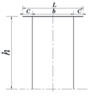
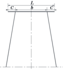
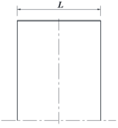
The load-bearing structure of a Tainter gate is composed of a radial plate, main beams, secondary beams, vertical bracing systems or separators, gate arms, and gate hinges. The main frame is the main loading-bearing structure of a Tainter gate; it bears the water pressure transferred from the plate and the secondary beam and transfers it to the gate hinges; therefore, the main frame determines the safety and economy of the entire Tainter gate structure. The main frame structure can have either a horizontal beam frame structure or a vertical beam frame structure, depending on the width–height ratio β of the orifice. When β ≤ 0.6, a main vertical beam frame structure is more suitable, whereas when β ≥ 1.4, a main horizontal beam frame structure is apt; when 0.6 < β < 1.4, the arrangement form and number of main girders depend on the total water pressure (Liu et al. 2010). The main horizontal beam frame structure of a Tainter gate consists of a horizontally placed main horizontal beam on gate arms, as shown in Figure 6. Figure 6(a) shows a straight gate arm frame with a cantilever, and Figure 6(b) shows an inclined arm radial gate frame, where the gate arms are inclined with the main beam. According to the design code, the length of the cantilever at both ends of the main beam should be 0.2L (where L is the span of the main horizontal beam). Figure 6(c) shows a straight gate arm frame without a cantilever. The main beam and gate arm are orthogonal to each other, and the gate arm is located at both ends of the main beam. In fact, both (a) and (c) are special cases of (b); when the length of the cantilever (c) is zero, (b) becomes (c) and when the gate arm is perpendicular to the main beam, (b) becomes (a). From the perspective of civil construction and whole structure safety and economy, (b) has comprehensive advantages. Given the continuous improvement of modern manufacturing levels, manufacturing of the complex structure of the articulated gate hinge is no longer a problem.
|
|
|
| (a) | (b) | (c) |
Since 1949, most water conservancy and hydropower projects have adopted Tainter gates and have withstood the trial of complex environments in China. At present, China’s large-scale water conservancy projects are in the rapid development stage and most of them are large- or medium-scale types (Zhang et al. 2018); for such projects, Tainter gates are particularly suitable and can be appropriately modified according to the needs of the project. Tainter gates are the most promising for service gates with high heads or large orifices, and so they are used worldwide for such situations (He 1991). In the past 20 years, China’s high dams and large reservoirs have developed rapidly, and Tainter gates are more widely applied than are plane gates as they require gate piers with low height and thickness and do not entail gate slots that affect the water flow regime. In addition, their hoisting capacity is small, they require fewer gate buried parts, the water flow is smooth before and behind the gate, and the overflow condition is appropriate. The construction cost of a high-water-head Tainter gate is also lower than that of a plane gate of the same size.
4.1.2 Plane gate
In the 1950s and 1960s, a period of economic slowdown in China, plane gates were widely used in water conservancy and hydropower projects. Plane gates have such advantages as simple structure, easy installation and maintenance, and interchangeability. However, these gates have such disadvantages as large hoisting capacity, poor local opening conditions, presence of gate slots that affect water flow, and vulnerability to gate vibration and cavitation damage. In particular, with the construction of high-water-head power stations and large-scale hydrojunctions, the application of plane gates has been limited. Per the gate leaf structure, plane gates can be classified into vertical lift gates, horizontal lift gates, horizontal pull gates, rotary gates, float sinking gates, transverse stacking gates, and vertical row gates. The main structure arrangement of a plane gate is determined on the basis of the components that need to be set on the gate, the number of each type of components needed, and the location of each component. Whether the structural arrangement is reasonable relates directly to factors such as whether the gate is easy to use, safe, and durable; saves material; requires simple construction method; and is easy to manufacture. The design must be considered in overall consideration and arrangement. A plane gate is composed of three parts: the gate leaf structure, buried parts of the gate slot, and the mechanical equipment for opening and closing the gate. The gate leaf structure is a type of water-retaining structure, which is mainly composed of panels, beam grillages, coupling systems, and other components.
Plane gates comprised of beam grillages can be classified as pure main beam-type, primary-secondary beam-type, and ordinary-type plane gates. In the pure main beam type, no secondary beam is installed between the main beams. The panel is directly supported on the main beam, and the water pressure on the panel is transmitted directly to the side beams on both sides through the main beam. It is simple to manufacture and involves a simple force transfer method. However, it requires a thicker panel, so it is suitable only for gates with a small span and a large height. The primary-secondary beam consists of vertical secondary beams arranged between the main beams to increase the support of the panel. In this arrangement, the water pressure from the gate panel is transmitted to the main beam through the secondary beam and then to the support side beam. This beam system is suitable for medium-span gates. The ordinary type consists of horizontal secondary beams set between the vertical secondary beams to maintain an economical panel thickness. This type of beam system is most commonly used in engineering applications.
4.1.3 Miter gate
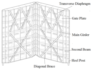
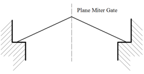
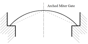
Miter gates are mainly used as service gates for large or medium ship locks because of their reasonable arrangement structure and form, convenient and reliable operation, small raising force, and low material requirement. A miter gate can be classified as plane miter gates and arched miter gates, as shown in Figures 7 and 8, respectively. In the design of Chinese ship locks, the service gates are subjected to medium or high water head and are opened and closed under static water conditions. For example, the Three Gorges (with a maximum gate height of 38.5 m), Gezhouba, and other projects have used miter gates as service gates.
A miter gate is composed of two gate leaves that rotate around a vertical axis. When the two gate leaves are closed, they are supported on each other’s diagonal stanchion to form a three-hinged arch such that the channel orifice is closed. Upon opening, the two gate leaves are separated and hidden in the threshold of the lock head’s side pier. The force condition of a miter gate is similar to that of a three-hinged arch, and the gate is especially advantageous for high-head and long-span ship locks. A miter gate is used as a service gate that opens and closes under a hydrostatic condition. Typically, it cannot withstand inverted water pressure, and even a small water head can cause the gate to suddenly open, causing an accident. Therefore, it is necessary to install a security device. The gate leaf has low torsional rigidity, which leads to easy distortion and deformation of the gate leaf during long-term operation.
|
|
| Figure 7 Schematic of plane miter gates | Figure 8 Schematic of arched miter gates |
A miter gate mainly consists of the following components. 1) Panels: they connect with the vertical beams, main beams, and secondary beams and directly withstand the water pressure. 2) Main beams: they are the main load-bearing members of the gate and generally use solid-web I-shaped sections. 3) Vertical beams: these components are set perpendicular to the direction of the main beams and connect the main beam to increase the integral rigidity of the gate. They are mostly solid-web I-shaped sections. 4) Horizontal secondary beams: these are placed between the main beams to reduce the thickness of the panels. 5) Top hinges: they are the upper bearings that prevent the gate from overturning and ensure the gate maintains its vertical position. 6) Bottom hinges: they are important and complex components that bear the vertical dead weight of the gate and form the theoretical axis together with the top hinges when the gate opens or closes. 7) Push–pull rods: they are important components connecting the gate and the hydraulic hoist. During the opening process, the push–pull rod bears the axial pull force, whereas during the closing process, it is in a pressured state. 8) Back tie rods: they increase the stiffness of the entire gate, especially the back position to prevent the gate from deformation. Push–pull rods are set as decussation rods on the negative side water of the gate.
5 Gate design
The design of a gate is a systematic project. It is necessary to consider all aspects and ultimately ensure that the design of a gate structure is convenient to use, advanced in technology, and economically rational. The following information is essential for gate design: 1) The situation of the hydraulic structure, such as the gate’s function, scale, importance, operational characteristics, and specific structural arrangements. 2) The condition of the gate orifice, orifice scale, number of orifices, and requirements for gate operating procedures. 3) The upstream and downstream water level conditions of the gate. 4) Water quality of reservoirs, especially for reservoirs with large sediment contents, considering the influence of siltation on the gate and hoisting capacity. 5) The meteorological and seismic data of the location of the reservoir, mainly including whether the reservoir freezes in winter, whether discharge of ice is required, and whether the reservoir region is susceptible to earthquakes. 6) Manufacturing and installation of gate. If the gates are manufactured at a factory, the limited load and height of the roads along the way must be considered. In addition, the gate should be placed at a position where the water flow is relatively smooth, which prevents lateral flow and vortex in front of the gate; the outflow and backflow should be submerged behind the gate; and the bottom and top of the gate should be filled with water simultaneously should be avoided.
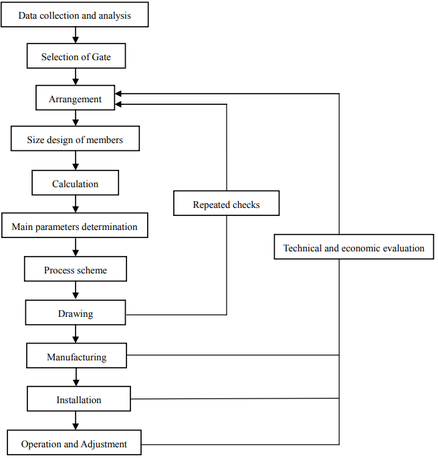
The gate design process is shown in Figure 8.
5.1 Planar system method
The current gate design code of China is based on the structural mechanics method and allowable stress method of a planar system. Although the calculation is simple and easy, it does not accurately reflect the interrelationships between the components of the entire gate. The planar system method divides the spatial structure into several independent planar structural systems and determines the strength, stiffness, and stability on the basis of the actual most-likely unfavorable load combinations under both basic and special load combination conditions, such as those related to panels, beams, main beams, and arms. This method uses a clear and simple calculation concept and is accepted by the majority of designers. For the longitudinal beams and panels of Tainter gates, the influence of curvature is ignored, and the loadings on these members are determined approximately assuming a straight beam and plate. The loading component and connector of a gate should be checked for normal stress, shear stress, and reduced stress as well as for the components bearing normal stress and shear stress. For bending, compression, and eccentric compression members, the overall and local stability should be checked. However, the planar system method calculates the gate structure separately, ignoring the coordination of the overall work of each component and thus does not reflect the spatial effect of the Tainter gate structure. The design is generally conservative, resulting in excessive gate material (20%–40%), wastage of material, and increased hoisting capacity. The specific design flow of the planar system method is shown in Figure 9. The specific structural calculations mainly include those of panels, bottom beams, top crossbeams, small horizontal beams, vertical separators, gate arms, internal forces of frameworks in the transient of gate opening, global stability of arms, local stability of arms, side longitudinal beams, and raising forces.
5.2 Spatial system method
The spatial system method analyzes and calculates the gate as a whole spatial frame system. Practically, a gate is a complete spatial structural system, with its components coordinated with each other. The external force and load acting on the gate structure are shared by all the components. When calculating the internal force of each component according to the plane system, irrespective of how fine the assumption is, it does not fully reflect their true working conditions. The analysis of the gate structure according to the spatial system formally started only after Vlazov’s theory of opening a thin-walled frame structure was proposed (Anhui Survey and Design Institute of Water Conservancy and Hydropower. 1980). The rapid development of the spatial finite element method has enabled complete analysis and calculation of a gate structure in accordance with the spatial system, which fully considers the integrity, spatial force characteristics, and deformation characteristics of the gate as a spatial structure. The Soviet Union was one of the earliest countries to begin applying this spatial structural analysis method. Chinese design companies, universities, and research institutions have been utilizing the spatial structural analysis method to analyze and calculate Tainter gate structures. Using the spatial finite element method to calculate the gate structure, the strong spatial effect of the gate is fully reflected and the stress and deformation of each component can be accurately calculated. It can not only result in conservation of materials and weight reduction of the gate but also improve the overall safety of the gate. The spatial system calculation method can be used as a method for verifying the planar system calculation method in order to ensure safe operation of a Tainter gate structure. Using the spatial finite element method to analyze the static and dynamic characteristics of the gate structure has become the typical approach.
From the perspective of accurate structural calculation and safety checking, it is necessary to use a structural finite element method to analyze the gate structure. Most of the design institutes and universities in China have applied the spatial finite element method for analyzing the gate structure since the 1970s. In the past forty years, the method has been increasingly applied; for example, Lanzhou University et al. (Lanzhou University Department of mathematics and mechanics 1977) , Zhang Yulin et al. (Zhang et al. 1978) , Liu Lihua et al. (Liu et al. 2004), Guo Guizhen et al. (Guo 2011), Hu Jianjie et al. (Hu et al. 2014), Lian Ziyi et al. (Lian 2017), and Li Sangjun et al. (Li et al. 2018). In addition, commercial finite element software packages have advanced and already incorporate the conditions for structural calculation. Although the finite element method is used to analyze the structural strength, stiffness, and stability of a gate, there are differences to be compared with the current allowable stress method. Although how to deal with the problems of stress concentration in the analysis requires further research, these problems can be addressed by taking as reference relevant specifications and scientific research results, thus not affecting the application of the finite element method. Therefore, under the premise of using the planar system method for structural type selection and initial selection of member sections, the three-dimensional finite element method should be used for structural calculation and safety verification.
Gate vibration is a special hydraulic problem involving flow conditions, gate structures, and their interactions and is a category of fluid elastic theory. Although there are different explanations for the external cause of gate vibration, the natural vibration frequency of the gate is its internal cause. The natural frequency of the gate is an inherent parameter of the gate structure, which is determined by the structural rigidity, mass distribution, and material properties of the gate. In the current analysis of gate dynamics, most of the work is done by calculating the natural vibration frequency of the gate and comparing it with the excitation frequency of the force. When the excitation frequency of the force is close to or equal to the natural frequency of the gate system, the amplitude of vibration will gradually increase and the gate will resonate; this is regardless of whether the excitation frequency is intrinsic to the external force or it is a secondary frequency caused by the coupling of the structure and the water flow. Due to the damping effect, the amplitude does not increase indefinitely but will reach a large value, resulting in the intensive local or holistic vibration of the gate. Therefore, unusual stresses and strains occur in the gate structure, causing damage to the gate. Thus, in the designing of a gate, the self-vibration frequency of the gate structure can be set such that it is far from the high-energy fluctuating frequency region of the water flow by adjusting the rigidity, mass distribution, and material properties of the gate structure to ensure the safety of the gate structure. The following studies have used the spatial system method to analyze the dynamic characteristics of gates: Zhou Jianfang (Zhou et al. 1995), Xu Zhendong et al. (Xu et al. 2001), Cao Qing et al. (Cao et al. 2001), Liu Yakun et al. (Liu et al. 2005) , Niu Zhiguo et al. (Niu et al. 2008), Lan Wengai et al. (Lan et al. 2011), Zhao Lanhao et al. (Zhao et al. 2017), and Chang Fu et al. (Chang et al. 2018) .
5.3 Probabilistic limit state design method based on reliability
In the United States, the “Hydraulic Steel Structure Design”(Design of hydraulic steel structures 2014) stipulates that the structural design can be carried out using the load resistance factor method and the allowable stress method. The “Spillway Tainter Gate Design” standard (Design of spillway tainter gates 2000) and “Plane Gate Design” standard (Vertical lift gates 1997) stipulate that the structural design must use the load resistance factor method. In addition, the American Steel Structure Association, American Highway and Transportation Association, and the American Welding Society also require that the structure be designed using the load resistance factor method. In China, the “Design Code for the Steel Structures” (Ministry of Construction of the People's Republic of China 2003)stipulates that, with the exception of fatigue calculation, a limit state design method based on probability theory should be adopted, and the design expression of the partial coefficient is nearly the same as that of the United States. Many scholars have conducted relevant research on the reliability of hydraulic gates. Fan Chongren (Fan et al. 1992) and Zhou Jianfang et al. (Zhou 1995) have discussed the reliability of the gate design code, and Wang Zhengzhong (Wang et al. 1998) proposed a series and parallel model and calculation method for the reliability calculation of a Tainter gate spatial frame system. Li et al. proposed(Li et al. 2003) a life prediction method based on the reliability theory for active steel gate structural members. Li (Li 2016) evaluated the fatigue reliability of steel gates on the basis of Bayes’ theorem, and Yan Genhua and Yan Shiwu (Yan et al. 1996) proposed an expression suitable for calculating the flow-induced vibration dynamic reliability of a gate on the basis of an overtaking mechanism. However, the lack of statistical data of hydraulic gate loads and the unclear failure criterion are the bottlenecks hindering the application of the probabilistic limit state method. This is mainly attributed to the harsh working environment of hydraulic gates, complex operating conditions, various forms of damage, and complex mechanisms. It is difficult to accurately calculate the load and resistance indicators in the limit state equation. Consequently, in the current design of China’s water conservancy and hydropower gates codes, the allowable stress method is still being used.
The basis of the probabilistic limit state design method is a large number of statistical parameters. Therefore, it is necessary to continue with the observation of gate prototypes, collect statistical data of various types of gate flow loads under various operating conditions, and determine the probabilistic and statistical characteristic parameters of the load and various partial coefficients. In addition, it is necessary to study the parametric vibration and dynamic instability mechanisms of gates during the discharge process, explore structural dynamic failure criterion, and lay the foundation for the application of the hydraulic gate probabilistic limit state method.
6 Design basis of gate in international projects
The quality of water conservancy and hydropower projects in China has reached international standards. With the continuous reduction of the stock of hydropower resources under construction in China (Han et al. 2014), internationalization has become a trend; however, international practice is based on the seamless connection between design codes and international standards. At the core of engineering design lies the code; therefore, systematic research and mastering of international codes is the starting point for taking the country toward overseas markets; it is also the key to strengthening international competitiveness. China’s current codes are “Design Code for Steel Gate in Water Resources and Hydropower Projects (SL74-2013)” and ”Design Code for Steel Gate in Hydropower Projects (NB35055-2015).” The current U.S. codes are “Hydraulic Steel Structure Design” (2014), “Spillway Tainter Gate Design” (2000), and “Plane Gate Design” (1997). The current European code is “Hydraulic Steel Structure Design (Hydraulic steel structures—Part 1 2014; Hydraulic steel structures—Part 2 2014; Hydraulic steel structures—Part 3 2014). The U.S. codes and the European codes use the limit state design theory and partial coefficient design based on the probabilistic limit theory, but the Chinese specifications adopt the allowable stress method. Therefore, the Chinese gate design codes are lagging behind the U.S. specifications and the European specifications. To ensure that gates designed using Chinese gate design codes are safe and economical as well as can better integrate with international specifications and participate in international water conservancy and hydropower projects, China should accelerate the research and application of the probabilistic limit state method for design specifications of hydraulic gates. When designing international water conservancy and hydroelectric engineering gates, the design specifications should be selected according to the requirements of the owner's engineers. The internationally accepted design codes are generally American and European specifications.
7 Development trend of gates
Since the first use of gates in hydropower projects, they have developed in tandem with the socioeconomic advancement and progress of science and technology. To meet the needs of the construction of the high dams and large reservoirs, gates have continuously developed in terms of large span, high gates, high head, large scale, light weight, and esthetic value. The calculation theories and methods for gates are constantly evolving through integration of modern computing technology and information technology, specifically the integration of structural calculation, structural optimization, structural design, structural manufacturing, CAD(Computer Aided Design)/CAE(Computer Aided Manufacturing)/BIM(Building Information Modeling), as well as 3D printing. Regarding materials, structures, connection methods, and design methods of gate, the application of super-strength steel in the construction industry, the bionic technology in the engineering structure, the plastic welding technology in the automotive industry ( Chang D et al. 1974; Wang et al. 2013 ), and the international advanced design methods are expected to become trends.
Use of high-strength or super-strength steel: With the continuous construction of large-scale projects such as high dams and large reservoirs, large or super-large hydraulic gates will be required to bear immense water thrust. Conventional steels will be inefficient in terms of operational flexibility as well as would pose difficulties in manufacturing, transportation, and installation. To reduce deadweight, especially with the continuous improvement of China’s super-strong steel technology and industrial production (He et al. 2017), using super-strong steel for large or super-large gates will become a trend.
Use of bionic structure: To solve the problem of buckling instability of the gate arm, the method of biomimetic mechanics is used. The methods simulating the “universal hinge” of an animal’s long bones and the honeycomb structure are used to solve the problem of instability of gates, because it is mostly caused by the buckling of the arm under the action of hydrodynamic load. Using this method of simulating the universal joint, the bending moment generated by the dynamic load of a gate leaf cannot be transmitted to the arm, thus ensuring axial compression of the arm and improving its static and dynamic stability. Similarly, applying a layer of damping material on the surface of the arm in the form of simulating an animal’s long bone can reduce the vibration effect of the gate leaf load on the arm and thus improve the stability of gates.
Use of adhesive bonding technology: Chang et al. (Chang et al. 1974) found that super-light adhesive connection has the advantages of simple construction, nonresidual stress, significant reduction of stress concentration, high bonding strength, and reliable connection characteristics of dissimilar materials; these features can increase the rigidity, strength, and durability of a structure. Wang Laiyong et al. (Wang et al. 2013) invented structural adhesive for bonded steel, which has good adhesive properties; this steel imparts uniform stress distribution, high shear strength, and good mechanical toughness to the structure. In addition, the adhesive bonding technology has the advantages of both adhesive bonding and welding. The fatigue resistance of a soldered joint is better than that of a welded joint. Using this new and developing adhesive bonding technology in the connection of gate structures, many problems of structural welding and bolting can be solved.
Use of international advanced gate design methods: To ensure that gates designed using Chinese gate design standards are safe and economical and can be integrated with international standards as well as to better participate in the design and construction of international water conservancy and hydropower projects, China’s relevant gate design codes should adopt a limit state design theory and multi-partial coefficient design based on probability limit theory.
Acknowledgments
The authors wish to acknowledge the financial support provided by the Ministry of science and technology of People's Republic of China. The authors would like to express their special thanks the chief editor of the Journal, who assisted with the good suggestions for revision.
References
Anhui Survey and Design Institute of Water Conservancy and Hydropower. (1980). Design of hydraulic steel gate [M]. Beijing: Water Conservancy and Electric Power Press.
Cao Qing, Wang Guanglun, Cai Junmei. (2001). Study on vibration characteristics of radial gate[J]. Water resources and hydropower engineering, 32(5): 16-20.
Chang D, Muki R. (1974). Stress distribution in a single lap joints under tension-shear [J]. International Journal of Solid and Structures, 10(5): 503-517.
Chang Fu, Ji wei. (2018). Fluid-solid coupling analysis of the panel steel gate and its structural optimization[J]. Journal of water resources and architectural engineering, 16(2):184-188.
Department of Construction and Management of the Ministry of Water Resources, Dam Safety Management Center of the Ministry of Water Resources. (2012). The top 100 highest dams in the world [M]. Beijing: China Water & Power Press.
DIN 19704-1, (2014). Hydraulic steel structures—Part 1: Criteria for design and calculation [S]. Berlin: Deutsches Institut fur Normung E.V. (DIN).
DIN 19704-2, (2014). Hydraulic steel structures—Part 2: Design and manufacturing [S]. Berlin: Deutsches Institut fur Normung E.V. (DIN).
DIN 19704-3, (2014). Hydraulic steel structures—Part 3: Electrical equipment [S]. Germany: Deutsches Institut fur Normung E.V. (DIN).
Zheng Shouren. Discussion on safety and construction of high dams in China [A]. CHINESE NATIONAL COMMITTEE ON LARGE DAMS. Technical progress in reservoir dam construction and management-Proceedings of the 2012 annual academic meeting of CHINESE NATIONAL COMMITTEE ON LARGE DAMS [C]. CHINESE NATIONAL COMMITTEE ON LARGE DAMS, 2012:9.
Fan Chongren, Xu Dexin. (1992). Reliability analysis of hydraulic steel gate [J]. Water Power, (8): 34-39.
Guo Guizhen. (2011). Researches on Property and Numerical Calculation of Flow-induced Vertical Vibration of Plate Gate[D]. Tianjin: Tianjin University.
Han Dong, Fang Hongwei, Yan Bingzhong, et al. (2014). China's hydropower status in 2013[J]. Journal of Hydroelectric Engineering, 33(5): 1-5.
He B B, Hu B, Yen H W, et al. (2017). High dislocation density-induced large ductility in deformed and partitioned steels[J]. Http://Science 10.1126/science.aan0177.
He Yunlin. (1991). The present situation and developing trend of gates in the world[J]. Journal of Northwest Agricultural University, 19(4): 85-93.
He Yunlin. (1993). Dynamic development of the hydraulic gate [J]. Journal of Hydroelectric Engineering, , 12(3): 87-97.
Hu Jianjie, Hu Youan, Chen Weichong, et al. (2014). Numerical analysis on static for cambered triangular gate[J]. Journal of water resources & water engineering, 25(2):218-221.
Lan Wengai, Zhao Xinming, Tang Yong, et al. (2011). Study on structural dynamic performance of hydraulic radial working gate[J]. Water resources and hydropower engineering, 42(4): 51-55.
Li Dianqing, Tang Wenyong, Zhang Shengkun. (2003). Prediction of remaining life for existing hydraulic steel gate structures [J]. Journal of Shanghai Jiaotong University, 37(7): 1119-1122.
Li Kun. (2016). Dynamic performance of water seals and fatigue failure probability updating of a hydraulic steel sluice gate [J]. Journal of Performance of Constructed Facilities, 30(4): 04015082.
Li Sangjun, Qin Zhansheng. (2018). Research on vibration characteristics of radial gate based on ansys by considering fluid-structure interaction[J]. Water Power, 44(1):64-67.
Lian Ziyi. (2017). Research on static and dynamic characteristics of three-arm radial gates[D]. Hubei: Wuhan university.
Liu Jiliang, Wang Zhengzhong, Shen Yongkang, et al. (2010). Arm section optimization and optimal number of radial gate arms located in deepwater delivery structures[J]. Journal of Hydroelectric Engineering, 29(5): 147-152.
Liu Liuyan, Wen Liping. (2016). Analysis on high dam large reservoir statistics in China[J]. water conservancy construction & management, 36(9): 12-16.
Liu Yakun, Ni Hangen, Ye Ziqing, et al. (2005). Analysis of flow-induced vibration of hydraulic radial gate[J]. Journal of Dalian University of Technology, 45 (5): 730-734.
Lv Niandong, Liu Lihua, Li Cuihua. (2004). Static tests and 3D FEM analysis for new radial gate in Huangtankou hydropower station[J]. Dam and safety, 19 (3): 75-78.
Ministry of Construction of the People's Republic of China. (2003). Code for design of steel structures: GB 50017—2003 [S]. Beijing: China Planning Press.
Ministry of Water Resources of the People's Republic of China. (2013). Design code for steel gate in water resources and hydropower projects: SL 74-2013 [S]. Beijing: China Water & Power Press.
National Energy Administration. (2015). Design code for steel gate in hydropower projects: NB35055-2015 [S]. Beijing: China Power Press.
Niu Zhiguo, Li Tongchun, Zhaolanhao, et al. (2008). Finite element analysis of parametric vibration of radial gate[J]. Journal of Hydroelectric Engineering, 27(6): 101-105.
The four Bureau of Hydropower Design Institute, Lanzhou University Department of mathematics and mechanics. (1977). Finite element method for stress analysis of radial steel gate[J]. Journal of Lanzhou University, (1): 53-74.
USACE. (1997). Vertical lift gates: CECW-ED Engineer Manual, 1110-2-2701 [S]. U S Army Corps of Engineers (USACE), Washington D C.
USACE. (2000). Design of spillway tainter gates: CECW-ET Engineer Manual 1110-2-2702 [S]. US Army Corps of Engineers (USACE), Washington D C.
USACE. (2014). Design of hydraulic steel structures: CECW-CE Engineer Manual 1110-2-584 [S]. US Army Corps of Engineers (USACE), Washington D C.
Wang Laiyong, Pang Zhihua, Li Chengchang, et al. (2013). The structure of adhesive for bonding steel: CN101921566B [P].
Wang Zhengzhong, Li Zongli, Li Yalin. (1998). Analysis of reliability of the steel arch-gate space frame system [J]. Journal of Northwest Agricultural University,, 26(4): 35-40.
Wang Zhengzhong, ZHANG Xuecai, LIU Jiliang. (2017). Advances and developing trends in research of large hydraulic steel gates[J]. Journal of Hydroelectric Engineering, 36(10): 1-18.
Xu Zhendong, Du Lihui, Cai Junmei. (2001). Study on the free vibration characteristics of liquid-solid coupling of plane gate[J]. Water Power, 27(4): 39-44.
Yan Genhua, Yan Shiwu, Luo Shaoze, et al. (1996). Dynamic Reliability study of filling value in navigation lock of high water head[J]. Journal of vibration, measurement & diagnosis, 16(2): 36-43.
Zhang Sherong, Pan Fei, Wu Yue, et al. (2018). Study and application of BIM-EPC collaboration platform in hydropower construction projects[J]. Journal of Hydroelectric Engineering, 37(4): 1-11.
Zhang Yulin, FAN Hengxin. (1978). The finite element calculation method of hydraulic steel gate [J]. Journal of Northwest University(Natural Science Edition), 22(1): 27-35.
Zhao Lanhao, Luo Peng. (2017). Calculation and analysis of flow-induced vibration in large-scale hydraulic steel radial gate through numerical and physical models[J]. Water resources and power, 35(12):173-177.
Zhou Jianfang, Li Guorui. (1995). Calculation of the natural frequency of main frame in radial gate[J]. Journal of hydraulic engineering , 26(4): 49-55.
Zhou Jianfang. (1995). Calculation of reliability according to the design criteria for steel gate of hydro project [J]. (11): 24-29.
Document information
Published on 16/11/18
Submitted on 08/11/18
Licence: CC BY-NC-SA license
Share this document
claim authorship
Are you one of the authors of this document?
