Abstract
The dynamic response characteristics of an earth-rock fill dam on a deep overburden are the focus of seismic research. In particular, evaluating the influence of the earthquake safety of the dam. A dynamic response analysis of earth-rock fill dam on a deep overburden based on viscoelastic boundary conditions was used to study the influence of boundary conditions (including fixed boundary conditions and viscoelastic boundary conditions). The results show that the fixed boundary condition greatly improves the dynamic response level of the dam during an earthquake and has no obvious influence on the distribution of the acceleration response in the dam and the foundation. The difference in the calculation results under the two boundary conditions is related to the seismic input characteristics and dynamic deformation characteristics of the soil material. An analysis of the acceleration response spectrum shows that the influence of the boundary conditions on the calculation results is limited to the magnitude level of the acceleration response, while the spectral characteristics of the vibration of the dam and the foundation do not have a significant impact.
Keywords: Deep overburden, earth-rock fill dam, seismic response analysis, boundary conditions, comparative analysis
1. Introduction
China’s western region is rich in water resources and is currently the key location of china’s hydro-power development. There are a large number of dams under construction or that will be built. However, this is mostly a high-seismic-intensity area, and there have been many earth-rock fill dam projects built using the complex seismic characteristics of the river valley deep overlay. Under the action of earthquake, the acceleration response of dam body and overburden is closely related to the safety of the dam, and it is an important factor to study the damage mechanism of earth-rock fill dams under the action of earthquakes and the seismic measures [1-4]. Therefore, the deep overlay dam-foundation system dynamic response characteristics have become a focus of attention for engineering and technical personnel, and are a hot spot of seismic dam research.
Many experts and scholars from all over the world have explored various methods and simulated practical projects based on the seismic response analysis of earth-rock fill dams: Bureau, Seed and Zhao et al. [5-9] carried out numerical simulation analysis on seismic response of practical engineering; Yang [10] introduced three kinds of artificial boundary conditions (mainly including transmission boundary, viscous boundary and viscoelastic boundary) widely used in structural dynamic analysis, commented on their advantages and disadvantages, and emphatically analyzed the application of viscoelastic artificial boundary in dynamic analysis of earth rock dams on overburden Problems and solutions; Zhou [11] discussed viscoelastic artificial boundary and its seismic wave input method and seismic response analysis method of earth rock dam considering traveling wave effect and foundation radiation damping; Xu, Zhu and Hou [12-15] studied the random seismic response and failure probability of high CFRD under random earthquake excitation; Liu [16] and Luan [17] considered the amplitude and phase changes of wave induced human radiation. According to the influence of structural response and the radiation effect of scattered waves, the structural dynamic interaction analysis under ground motion is realized by using the latest general structural dynamic analysis software. Kong [18], using the incremental dynamic analysis (IDA) method, I comprehensively and deeply analyzed the variation of structural energy under different earthquake intensities. These research results are extremely important for guiding the design and construction of the dam and reducing the earthquake damage of the dam.
When the thickness of the overburden is higher than that of the dam, the foundation of the overburden should not be considered in the dynamic analysis of the dam. Only the near part of the dam cover as a near-area foundation dam structure, along with the dam, is considered as the object of the computational analysis. In this case, the near-field ground cut-off boundary processing method will have a significant impact on the accuracy of the results.
Currently, the truncated boundary treatment is mainly accomplished using fixed artificial treatment, and thus the dilettante scattered waves cannot diffuse through the model boundary to the far-field foundation. Instead, this is all reflected back inside the model. The “radiative damping” effect of the far-field foundation cannot be reflected, and this significantly increases the dynamic response level of the dam structure[19]. In the study of structure-ground dynamic interaction, viscoelastic boundary conditions that can reflect the "radiation damping" effect of distant ground and absorb some seismic energy are widely used instead of fixed boundary conditions [20]. Replacing fixed boundary conditions with viscoelastic boundary conditions that are widely used in current studies of structural-foundation dynamic interactions and can reflect the "radiation damping" effect and elastic recovery performance of distant ground, can eliminate or effectively reduce the imperviousness of travelling waves due to truncated boundaries The calculation error caused by crossing the boundary, the dynamic response level of the dam is closer to the actual value [21–23].
The main research results when considering the dynamic reaction characteristics of earth- rock fill dams are based on fixed boundary conditions. the dynamic responses of earth-rock fill dams with a deep overburden are based on viscoelastic boundary conditions. It is necessary to study the dynamic response characteristics of dams during earthquakes and compare them with the results of the fixed boundary condition. In this paper, the authors apply an equivalent seismic inertial force to solve the seismic input problem of the dynamic analysis of earth-rock fill dams with a deep overburden under the viscoelastic boundary condition. At the same time, a dynamic response analysis method based on the viscoelastic boundary condition of deep-overburden rock dams is established by using the equivalent linear analysis method and reflecting the dynamic non-linearity of the viscoelastic boundary condition on the boundary condition of the overburden foundation. Existing research results show that this method effectively solves the boundary conditions of dynamic analyses of seismic input problems under viscoelastic boundary conditions, and boundary conditions owing to nonlinear dynamic nonlinear boundaries caused by the soil. This is accomplished via seismic dynamic response analysis based on viscoelastic boundary deep-overlay research [24,25].
The dynamic response characteristics of the structural system during an earthquake are affected by the interaction of the dynamic characteristics of the structure itself and the seismic input characteristics [26]. The dynamic characteristics of the structure itself are mainly influenced by the dynamic characteristics and structural forms of the constituent materials, and the seismic input characteristics mainly refer to the amplitude levels and spectral characteristics of the seismic motions. In this paper, a dynamic reaction analysis method of a earth-rock fill dam with a deep overburden based on the viscoelastic boundary condition is used to analyze the dynamic reaction of the rock dam on the deep overburden, and to compare this with the calculated results for the fixed boundary condition. The influence of the boundary conditions on the dynamic response of the dam with a deep overburden is analyzed when considering the dynamic characteristics of the dam material and the differences of the seismic input characteristics.
2. Dynamic reaction analysis method and numerical example of rock dam with deep overburden based on viscoelastic boundary
2.1 Dynamic response analysis method of earth-rock fill dam based on viscoelastic boundary
Viscoelastic boundary conditions apply viscous dampers and linear springs to the composite mechanical elements of the foundation cut-off boundary to reflect the role of the foundation. The viscous dampers absorb the generalized structure during far-field foundation fluctuations of energy, and the linear springs reflect the elastic recovery of the foundation of the far-field [21,22]. The viscoelastic boundary physical model is simple, exhibits good numerical stability, has been widely used in structure-foundation dynamic interaction problems [23]. The key to the dynamic response analysis of a earth-rock fill dam on a deep overburden based on a viscoelastic artificial boundary condition is to solve the input problem of the earthquake. At the same time, the nonlinear dynamic deformation of the overburden soil on the boundary under viscoelastic boundary conditions is also a problem to be solved.
For exogenous excitation seismic problems can be approximated as endogenous excitation problems of multiparticle vibration. By applying the equivalent seismic inertia force, this is considered to be simultaneously equivalent to the role of the earthquake on the internal structure of all nodes and the role of a seismic acceleration of the same time. At the same time, the seismic acceleration is applied to the boundary nodes and internal nodes to reflect the role of the earthquake on the structure. The finite element equation for applying the foundation viscoelastic boundary-structural architecture dynamic equilibrium is as follows [25]:
|
|
(1) |
From the equation, , , (including internal nodes and boundary nodes) are the mass matrix, viscoelastic damping matrix (VDM) (VDM is defined according to the full Rayleigh damping formulation [27]), and elastic matrix. and are an additional damping matrix and an elastic matrix based on the viscoelastic boundary conditions. acts on the node equivalent seismic inertia force load vector. , , and are the acceleration, velocity, and displacement of the nodes, respectively. and represent the interior and boundaries of the model.
The finite element equation of dynamic equilibrium is applied to the viscoelastic boundary condition by using the seismic input method of the node inertia force. In addition to the stiffness and damping arrays generated by the springs and dampers on the boundary nodes, there is no change in the dynamic response of the earth-rock fill dam under the previous fixed boundary conditions compared to the analysis of the dynamic equilibrium finite-element equations. Based on the difference between existing fixed boundary conditions, this can be adjusted to apply the viscoelastic finite-element equations to solve the boundary conditions. Since they are easily combined with existing finite-element calculation procedures, the development of this program has continuity.
Adopt the same treatment method as the internal soil, that is, use the equivalent linearization method to reflect the nonlinear characteristics of viscoelastic boundary conditions [25]. Under viscoelastic boundary conditions, the relevant mechanical parameters are directly or indirectly related to the amount of soil shear modulus and the dynamic shear modulus of the soil with the dynamic shear-strain changes of the nonlinear characteristics. The relationship is as follows ( is the maximum dynamic shear modulus of the soil, and is a reference shear strain):
|
|
(2) |
In the specific numerical calculation, the same viscoelastic boundary conditions in the iterative mode of strain modulus, the internal soil unit, and the internal soil can be used in the same way to consider the boundary conditions of nonlinear dynamic deformation of the physical model. This is an equivalent linearization mode and does not need special treatment. By examining the shear strain amplitude of the soil unit near the boundary, the dynamic shear modulus of the soil unit is determined. Then, the characteristic parameters of the viscoelastic boundary condition of the boundary node are determined.
The viscoelastic boundary conditions were applied to the structural dynamic response calculation process and the iterative model. The same was done with fixed boundary conditions [28]. Under the viscoelastic boundary condition, the structural dynamic equilibrium finite-element equation is compared with that of the fixed boundary condition, and an additional damping matrix and stiffness matrix are added. The explicit differential solution format of the finite-element equilibrium equation needs to be deduced again. On the basis of Wilson’s method for solving explicit differential equations for dynamic finite-element equations with viscoelastic boundary conditions, explicit differential equations for a structural dynamic equilibrium are derived [25].
Set ( is 1.4), and assume that time period , the acceleration changed in a linear relationship. , the time structure of the system node in the state of motion, can be expressed as
|
|
(3) |
|
|
(4) |
|
|
(5) |
According to the formulas, , , , , , , , and is the Rayleigh damping coefficient. , , and have the same meaning as mentioned.
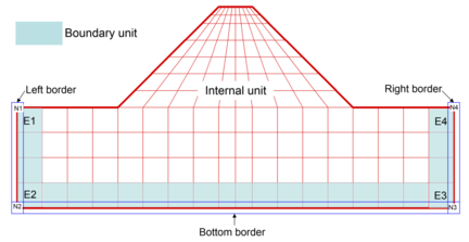
Using the above calculation method and the finite element program for a dynamic response analysis of earth-rock fill dam under fixed boundary conditions, a finite element program for the dynamic response analysis of earth-rock fill dam on deep overlying layers under viscoelastic boundary conditions is developed. In the finite element calculation of the dynamic response analysis of a dam based on viscoelastic boundary conditions, the model nodes are divided into internal nodes and boundary nodes. For a two-dimensional problem, the boundary nodes and cells are distinguished by the bottom boundary, the left boundary, and the right boundary. Figure 1 shows an example of a finite-element computational model for the dynamic response analysis of a earth-rock fill dam on a deep overburden with viscoelastic boundary conditions.
|
| Figure 1. Dynamic response analysis finite-element model of earth-rock dam applying viscoelastic boundary |
2.2. General example of dynamic response of earth-rock fill dam on deep overburden based on viscoelastic boundary
In view of the main work content of this article is to study the impact of boundary conditions on the dynamic response analysis results of the earth-rock fill dam on the deep overburden layer from the theoretical analysis level, so In order to facilitate the analysis and comparison of results, the calculation object is selected model of simple heart wall earth-rock fill dam dam on a deep overburden foundation. Using a simple earth-rock fill dam model on deep overburden, analysis the dynamic response of the dam under viscoelastic boundary conditions and compared with the calculation results under fixed boundary conditions. In order to compare the influence of boundary conditions qualitatively and quantitatively, the coverage thickness and width equal to the height of the dam were selected as the near-field foundation of the dam. The height of the model dam is 30m, and the model is completely consistent under the two boundary conditions. The finite element calculation model of the dam-foundation system is the same as that of Figure 1. The entire grid consists of 254 cells and 294 nodes, including 218 internal cells and 36 boundary cells with 257 internal nodes and 37 boundary nodes.
The initial stress field required for dam dynamic response analysis is determined based on static finite element calculation, and the stress-strain relationship of soil is expressed by Duncan-Zhang E-B model. The static and dynamic characteristic parameters of soil material parameters are determined with reference to actual projects. As shown in Tables 1 to 3, the cohesive force c and internal friction angle of the center wall are 89.0 kPa and 29.4°
| Dam material | Dry density (g/cm3) |
Strength parameter |
Deformation modulus parameter |
Bulk modulus parameter | ||||
|---|---|---|---|---|---|---|---|---|
| (º) | (º) | |||||||
| Dam and foundation | 2.25 | 52.7 | 9.5 | 0.8 | 1039 | 0.32 | 810 | 0.37 |
| Wall | 2.05 | — | — | 0.8 | 418 | 0.39 | 316 | 0.22 |
| Dam material | Dry density (g/cm3) |
C | n | Poisson’s ratio |
|---|---|---|---|---|
| Dam and foundation | 2.25 | 3894 | 0.456 | 0.40 |
| Wall | 2.05 | 600 | 0.500 | 0.48 |
| 0.0001 | 0.0005 | 0.001 | 0.002 | 0.003 | 0.004 | 0.005 | 0.01 | ||
|---|---|---|---|---|---|---|---|---|---|
| Dam and foundation | 85 | 59 | 40 | 25 | 19 | 15 | 14 | 12 | |
| Wall | 95 | 70 | 53 | 37 | 28 | 25 | 24 | 21 | |
| Dam and foundation | 7.0 | 17.0 | 21.8 | 24.8 | 26.8 | 27.8 | 28.0 | 28.2 | |
| Wall | 12.0 | 18.0 | 22.0 | 24.0 | 25.0 | 25.5 | 25.7 | 26.0 | |
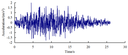
A real engineering site wave (seismic wave A) is used as the input. The peak acceleration of the input is adjusted to 0.2 g. The normalized acceleration time of the input is shown in Figure 2.
|
| Figure 2. Input seismic acceleration time course |
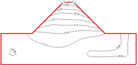
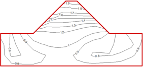
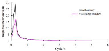
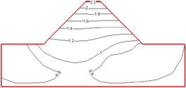
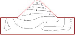
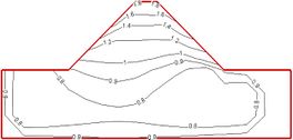
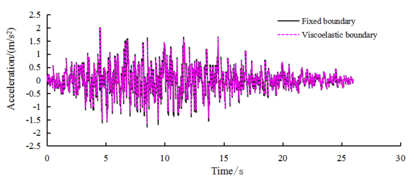
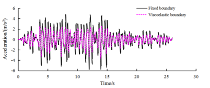
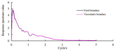
Figure 3 shows a comparison of two boundary conditions: the dam and foundation internal acceleration magnification distributions. Figure 4 shows a comparison of two boundary conditions: the dam vertical center line of the bottom boundary nodes and the dam top-node vibration acceleration time curve. Figure 5 shows a comparison of two boundary conditions: the dam vertical center line of the bottom boundary nodes and the top node of the vibration absolute acceleration reaction spectrum curve.
|
| (a) Bottom border junction |
|
| (b) Top of dam node |
| Figure 4. Comparison of time course of node’s horizontal acceleration toward vibration under conditions of fixed boundary and viscoelastic boundary |
|
| (a) Bottom border junction |
| (b) Top node of dam |
| Figure 5. Comparison of absolute acceleration response spectrum of node to vibration level under conditions of fixed boundary and viscoelastic boundary |
It can be seen from Figure 3 that the acceleration response level of the dam obtained under the viscoelastic boundary conditions is generally much lower than the results obtained under the fixed boundary conditions. The fixed boundary processing method makes the calculation results of the dam dynamic response analysis larger a lot of. However, under the two boundary conditions, the distribution law of the internal acceleration response of the structure is basically the same: as the height of the dam increases, the acceleration magnification of the node vibration gradually increases, and reaches the maximum at the top of the dam; the acceleration response of the dam slope surface is higher The core wall in the middle of the dam has an amplification effect on the surface of the dam slope; the upper and lower dam toe areas each have an area with less acceleration response.
As can be seen from Figures 4 and 5, under viscoelastic boundary conditions, the bottom edge of the center-node vibration acceleration peak and preset input seismic peak are very similar. When the boundary level is fixed to the peak acceleration of a 0.2-g input, the boundary-node viscoelastic boundary acceleration reaction extremum is 0.191 g. From the waveform and the acceleration response, the spectral shape is basically the same. In addition to the top node on both sides of the boundary owing to the surface, the reaction and the fixed boundary input show a small difference, but the reaction and preset seismic input of other boundary nodes are basically the same.
Therefore, an equivalent inertial force is applied to the seismic input mode in the dynamic response analysis based on the viscoelastic boundary conditions of the earth-rock fill dam. This can effectively and more accurately implement the seismic input on the boundary of the model. Under the two boundary conditions, the dam top-center node vibration acceleration reaction process curve and acceleration response spectrum shape are basically the same relative to the seismic input and response spectrum of the extreme points, which move in the long-cycle direction.
However, the level of reaction is very different. The level of the acceleration peak is obtained at a fixed boundary condition of 0.642 g. The obtained acceleration peak of the viscoelastic boundary condition is 0.386 g, which is 39.9% lower than that of the fixed boundary condition. Using a fixed boundary significantly increased the level of acceleration response of the dam. In view of the magnitude of the acceleration response and its distribution in the dam, the acceleration response of the dam obtained under fixed boundary conditions is larger in magnitude than the viscoelastic boundary, but the qualitative distribution is consistent.
The dynamic response characteristics of the dam during an earthquake are mainly influenced by the material properties of the dam and foundation, as well as the seismic input characteristics. By adjusting the input parameters of ground motion and soil dynamic deformation characteristics, the influence analysis of ground motion characteristics and soil material characteristics under different boundary conditions is specifically analyzed.
3. Boundary-condition influence analysis considering seismic input characteristics
3.1 Influence of magnitude of earthquake
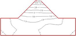
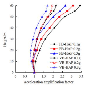
In the model example in Section 2.1, with its seismic input level to the acceleration peak adjusted to 0.1 g and 0.3 g under different seismic levels, the influence of the boundary conditions on the dynamic response characteristics of the dam structure were examined. Figure 6 shows the comparison of the magnification distribution of the horizontal acceleration inside the dam and the ground under two boundary conditions at different input acceleration levels Figure 7 shows two boundary conditions: the dam-foundation structure vertical centerline of the horizontal acceleration and the higher magnification contrast distributed along the dam. Table 4 lists the data for two boundary conditions: the dam top-center node level to the acceleration magnification and the input acceleration peak contrast.
|
| Figure 7. Comparison of distribution of horizontal-to-acceleration magnification along high- and midline of dam under conditions of fixed boundary and viscoelastic boundary |
From Figures 6, 7 and Table 3, and referring to Figure 3, it can be seen that after the viscoelastic boundary conditions are applied, the acceleration response level of the internal nodes of the dam is greatly reduced under the action of different levels of ground motion, and the level of reduction varies with the input ground motion Enhance and gradually increase. Therefore, the higher the earthquake intensity, the higher the magnitude of the larger the calculation result is due to the processing method of the fixed boundary. Under the two boundary conditions, the internal acceleration response distribution law of the dam and the foundation under different intensity ground motions is basically the same. When the input ground motion level is low (0.1g), the surface of the dam slope does not show obvious surface amplification effect. Under different ground motion levels, the ground motion input method of equivalent seismic inertial force can more accurately realize the ground motion input under the viscoelastic boundary.
| Horizontal input acceleration peak | 0.1 g | 0.2 g | 0.3 g |
|---|---|---|---|
| Fixed boundary | 3.51 | 3.21 | 3.08 |
| Viscoelastic boundary | 2.23 | 1.93 | 1.80 |
| Drop in viscoelastic boundaries relative to fixed boundaries |
37.4% | 39.9% | 42.2% |
3.2 Effects of seismic spectral characteristics
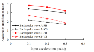
In order to investigate the influence of the seismic input spectrum characteristics, the model calculates the input seismic wave A (reaction spectrum extreme point period 0.11 s) based on input seismic wave B (reaction spectrum extreme point period 0.15 s), and compares the acceleration responses of the dam. The acceleration peaks of the two types of input seismic waves are exactly the same as when they were held in motion. Figure 8 shows two boundary conditions under the action of two kinds of seismic waves: the dam top-center node level and the acceleration magnification with input acceleration peak contrast changes. Table 5 shows the effect of seismic wave B and the viscoelastic boundary conditions of the acceleration magnification changes relative to fixed boundary conditions.
From Figure 8 and Table 5, and with reference to Table 4, at the same amplitude of seismic wave A and seismic wave B and the same fixed boundary conditions, the dam under viscoelastic boundary conditions obtained under the action of seismic wave B’s acceleration response is greater than that of seismic wave A. Different seismic waves cause different structural dynamic responses, mainly owing to differences in the characteristics of the seismic spectrum. As the viscoelastic boundary condition is applied only on the boundary of the spring-damper system, the additional elasticity and viscoelastic matrix on the boundary increases.
However, the internal structure of each feature matrix does not change. The effect of an additional matrix on the dynamic characteristics of the entire structure is very small. Therefore, the dynamic parameters of the viscoelastic architecture are basically unchanged, and the spectral relationships between the seismic waves are not changed. The first-order self-vibration cycle of the foundation system is about 2.5 s, which is more closer to the fundamental frequency of seismic wave B Thus, under the action of seismic wave B, the acceleration response is greater.
|
| Figure 8. Comparison of changes in horizontal-to-acceleration magnification of node with increase of input acceleration peak under action of different seismic waves |
| Horizontal input acceleration peak | 0.1 g | 0.2 g | 0.3 g |
|---|---|---|---|
| Fixed boundary | 3.80 | 3.60 | 3.21 |
| Viscoelastic boundaries | 2.65 | 2.35 | 1.89 |
| Drop in viscoelastic boundaries relative to fixed boundaries |
30.2% | 34.7% | 41.1% |
4. Analysis of boundary-condition influence considering dynamic deformation characteristics of soil
The soil has a maximum dynamic shear modulus subject to an average effective stress . This relationship can be expressed as
|
|
(6) |
In Eq.(6), and are the dynamic shear modulus coefficient and the dynamic shear modulus index and is the atmospheric pressure.
By examining the different boundary conditions of soil dynamic shear modulus coefficient and index and the changes to the acceleration of the dam, this study considered the dynamic deformation characteristics of the soil and the influence of boundary conditions on the dynamic response of the dam. Because the heart wall is relatively small proportion of the foundation system in the whole dam, the dynamic response characteristics of the dam have little effect, so we only consider the impact of the characteristics of the soil and earth-rock fill dam dynamic response parameters.
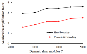
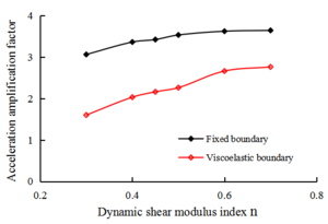
Tables 6, 7 and Figure 9 show the dam at a peak acceleration of 0.1 g under the action of seismic wave A, the horizontal acceleration magnification of the central node of the dam top changes with the change of the soil dynamic shear modulus coefficient and the index .
| Dynamic shear modulus () | 2500 | 3000 | 3500 | 3894 | 4500 | 5000 |
|---|---|---|---|---|---|---|
| Fixed boundary | 2.94 | 3.01 | 3.40 | 3.42 | 3.55 | 3.58 |
| Viscoelastic boundaries | 1.59 | 1.83 | 2.12 | 2.16 | 2.42 | 2.50 |
| Drop in viscoelastic boundaries relative to fixed boundaries |
45.9% | 39.2% | 37.6% | 36.8% | 31.8% | 30.2% |
| Dynamic shear modulus index () | 0.3 | 0.4 | 0.456 | 0.5 | 0.6 | 0.7 |
|---|---|---|---|---|---|---|
| Fixed boundary | 3.06 | 3.36 | 3.42 | 3.53 | 3.62 | 3.64 |
| Viscoelastic boundaries | 1.60 | 2.03 | 2.16 | 2.26 | 2.66 | 2.76 |
| Drop in viscoelastic boundaries relative to fixed boundaries |
47.7% | 39.6% | 36.8% | 36.0% | 26.5% | 24.2% |
|
|
| Figure 9. Influence of dynamic shear modulus coefficient C and dynamic shear modulus coefficient n on horizontal acceleration acceleration of nodes under different boundary conditions | |
As can be seen from Tables 6, 7 and Figure 9, under viscoelastic boundary conditions and fixed boundary conditions, the acceleration of the reaction level of the dam with the soil dynamic shear modulus coefficient and index increases. When these two values increased, the viscoelastic boundary acceleration reaction relative to the fixed boundary of the drop level gradually decreased. This shows that when the soil is relatively weak, the calculation error of the fixed boundary is large, and this error increases as the dam material stiffness gradually decreases. It can be seen that the boundary conditions have a greater influence on the calculation result than the concrete dam on the base rock surface. This is mainly because the cover layer is weak, the ability to absorb seismic energy (the “radiation damping” effect) is more obvious, and the foundation soil stiffness matches closely with the characteristics of the dam heap stone material. The wave impedance is relatively small and the reflection of the seismic waves is weak, so the actual seismic wave energy moves basically through the foundation and spreads to distant regions of the foundation.
By contrast, the viscoelastic boundary conditions relative to the fixed boundary conditions, the dam acceleration reaction drop level, and changes in and indicate that the fixed boundary conditions enhance the level of the dam acceleration reaction. Although and vary in different ways, because the structure of the reaction is caused by the fixed boundary lifting level, the magnitude of changes in and is larger. This is because the changes in and on the soil inside the dynamic shear modulus level along the depth of the changes are different. The soil dynamic shear modulus increases more quickly with the depth of change for larger values, so the bottom stiffness increases more quickly as well. When the rigidity is high, the calculation result of the fixed boundary condition is less than that of the viscoelastic boundary condition.
5. Conclusion
Based on an established dynamic response analysis method for mud-rock dams with deep overburdens and viscoelastic boundary conditions, and considering the effect of “radiative damping” and the elastic recovery performance of a remote foundation, the influence of the seismic input characteristics and soil material characteristics on the boundary conditions was studied. The main conclusions were as follows:
(1) Applying an equivalent seismic inertia force of the earthquake input can better meet the viscoelastic boundary conditions for a dam dynamic analysis and the seismic input to the calculation model boundary. This is applicable to the viscoelastic boundary conditions based on a deep overlay of the dam dynamic response analysis.
(2) Based on the viscoelastic boundary conditions, the analysis results for the dam dynamic response showed that the fixed boundary conditions significantly improve the dam during an earthquake according to the level of dynamic response. However, there was no significant impact on the distribution of the acceleration magnification inside the dam.
(3) Since the boundary conditions do not have a significant impact on the self-vibration characteristics of the structural system, the boundary conditions do not have a significant impact on the acceleration spectral characteristics of the dam vibration during an earthquake.
(4) Owing to different boundary conditions (fixed boundary conditions and viscoelastic boundary conditions), the dynamic response analysis indicated the following important factors in the seismic response characteristics: the differences, seismic input characteristics, and dynamic deformation characteristics of the soil material; the dam structure dynamic characteristics; and the spectral relationship between the inputs of the seismic dynamic dam.
Abbreviations
The following abbreviations are used in this manuscript:
N: Node
E: Elastic Modulus
VDM: Viscoelastic Damping Matrix
FB-HIAP: Fixed Boundary-Horizontal Input Acceleration Peak
VB-HIAP: Viscoelastic Boundary-Horizontal Input Acceleration Peak
Author contributions
Writing, original draft, L Wang; Writing, review and editing, J M Zhao; Conceptualization, data curation, Z Q Yang; Formal analysis, K B Zhu; Methodology, X G Wang; Supervision, validation, X S Liu.
Conflicts of Interest: The authors declare no conflict of interest. The founding sponsors had no role in the design of the study; in the collection, analyses, or interpretation of data; in the writing of the manuscript; nor in the decision to publish the results.
Acknowledgements
This work was financially supported by the National Key Research and Development Program of China (2017YFC0404905,2017YFC0404902), the National Natural Science Foundation of China (Grant No. 51509272), the special scientific research foundation of China Institute of Water Resources and Hydropower Research (GE0145B292017), the Public Service Sector R&D Project of Ministry of Water Resource of China (Grant No. 201501035).
References
[1] Feng D., Zhang G., Zhang J. Three-dimensional seismic response analysis of a concrete-faced rockfill dam on overburden layers. Frontiers of Architecture and Civil Engineering in China, 4(2):258-266, 2010. http://doi.org/10.1007/s11709-010-0031-4
[2] Zhu D.Y., Dong J.G., Kuang Q.B. Analysis of earthquake response of earth-rock dam on deep overburden. Water Resources & Hydropower of Northeast China, 29(11):51-52,63,72, 2011.
[3] Zhang D.P., Ma Z.Y. Analysis of earthquake acceleration responses of deep overburden high earth-rock dam. Journal of Water Resources and Architectural Engineering, 10(05):161-164, 2012. http://doi.org/10.3969/j.issn.1672-1144.2012.05.040
[4] Zhang R., Chi S.C., Lin Y., Zhang Z.L. Dynamic distribution of earthquake acceleration and its influence on the seismic stability of high earth-rock dam slopes. Rock and Soil Mechanics, 7(04):1072-1076, 2008. http://doi.org/10.16285/j.rsm.2008.04.014
[5] Bureau G., Volpe R.L., Roth W., Udaka T. Seismic analysis of concrete face rockfill dams. In: Proceedings of Symposium on Concrete-Face Rockfill Dams-Design, Construction, and Perfor- mance, ASCE, New York, 479-508, 1985.
[6] Seed H.B., Seed R.B., Lai S.S., Khamenehpour B. Seismic design of concrete-face rockfill dams. In: Proceedings of Symposium on Concrete-Face Rockfill dams-Design, Construction, and Perfor- mance, ASCE, New York, 459-478, 1985.
[7] Uddin N., Gazetas G. Dynamic response of concrete-faced rockfill dams to strong seismic excitation. Journal of Geotechnical Engineering, 121(2):185-1975, 1995. http://doi.org/10.1061/(ASCE)0733-9410(1995)121:2(185)
[8] Zhao J.M., Chang Y.P., Chen N. Study on earthquake-induced permanent deformation and dynamic stability of high concrete-faced rockfill dam. Chinese Journal of Rock Mechanics and Engineering, 23(supp1):4547-4552, 2004. http://doi.org/10.3321/j.issn:1000-6915.2004.z1.061
[9] Feng D.K., Hou W.J., Zhang G., Zhang J.M. Seismic response analysis on upper reservoir dam of Yixing power station. New Frontiers in Chinese and Japanese Geotechniques, 145-150, 2007.
[10] Yang Z.Q., Liu X.S., Dong C.S., Wang X.G., Zhao J.M. Artificial boundary treatment method for dynamic analysis of earth rock dams. Journal of Disaster Prevention and Mitigation Engineering, 35(04):440-446, 2015.
[11] Zhou C.G., Kong X.J., Zou D.G., Hu Z.Q. Application of viscoelastic boundary in seismic response analysis of earth rock dams. Proceedings of the 18th National Conference on Structural Engineering, Vol. III, Engineering Mechanics Editorial Department, Chinese Society of Mechanics, 2009.
[12] Xu B., Pang R., Zhou Y. Verification of stochastic seismic analysis method and seismic performance evaluation based on multi-indices for high cfrds. Engineering Geology, 264:105412, 2020. http://doi.org/10.1016/j.enggeo.2019.105412
[13] Li J.J., Ma H.C. Research on the dynamic property of CFRD in the period of water storage. Chinese Journal of Geotechnical Engineering, 17(4):20-27, 1995.
[14] Hou W.J., Zhang J.M., Zhang G. Dynamic response analysis of CFRD with extrusion-sidewall structure. Journal of Hydroelectric Engineering, 27(2):50-54, 2008.
[15] Zhu S., Gu G.C., Lin Y.C. Seismic response of CFRD on alluvial deposit. Journal of Hohai University, 25(3):80-85, 1997.
[16] Jingbo L., Yandong L. A direct method for analysis of dynamic soil-structure interaction based on interface idea. Developments in Geotechnical Engineering, 83:261-276, 1998.
http://doi.org/10.1016/S0165-1250(98)80018-7
[17] Zuo M., Wu X.Z., Yin J.Y., Xin J.X. Effects of dynamic properties of rock-fills on nonlinear seismic response of concrete face rock-fill dams. Journal of Hydroelectric Engineering, 28(1):8-18, 2001. http://doi.org/10.3969/j.issn.1003-1243.2001.01.002
[18] Kong X., Pang R., Zhou D., Xu B., Zhou Y. Seismic performance evaluation of high face rockfill dam based on IDA. Journal of Geotechnical Engineering, 40(6):978-984, 2018. http://doi.org/10.11779/CJGE201806002
[19] Chen H.Q. Discussion on input mechanism of dam site ground motion. Journal of Hydraulic Engineering, 37(12):1417-1423, 2006. http://doi.org/10.3321/j.issn:0559-9350.2006.12.004
[20] Wei W., Zhao Q., Jiang Q., Grasselli G. Three new boundary conditions for the seismic response analysis of geomechanics problems using the numerical manifold method. International Journal of Rock Mechanics and Mining Sciences, 105:110-122, 2018.
[21] Deeks A.J., Randolph M.F. Axisymmetric time-domain transmitting boundaries. Journal of Engineering Mechanics. ASCE, 120(1):25-42, 1994. http://doi.org/10.1061/(ASCE)0733-9399(1994)120:1(25)
[22] Liu J.B., Lv Y.D. A direct method for structural-foundation dynamic interaction analysis. Journal of Civil Engineering, 31(3):55-64, 1998. http://doi.org/CNKI:SUN:TMGC.0.1998-03-008
[23] He J.T., Ma H.F., Zhang B.Y. etc. Input method and implementation of viscoelastic artificial boundary ground motion. Journal of Hydraulic Engineering, 41(8):960-969, 2000. http://doi.org/10.13243/j.cnki.slxb.2010.08.015
[24] Yang Z.Q., Liu X.S., Zhou G.B., Liu Q.W., Zhao J.M., Yang Y.S. Experimental study of large shaking table model for seismic dynamic response characteristics of high panel rockfill DAMS. Journal of Vibration Engineering, 31(02):209-218, 2018. http://doi.org/10.16385/j.cnki.issn.1004-4523.2018.02.003
[25] Yang Z.Q., Liu X.S., Wang X.G., Zhao J.M., Wen Y.F. Viscoelastic boundary treatment method for dynamic analysis of earth-rock dams on deep overburden. Journal of China Institute of Water Resources and Hydropower Research, 15(3):200-2077, 2017. http://doi.org/10.13244/j.cnki.jiwhr.2017.03.006
[26] Yang Z.Q., Liu X.S., Wang X.G., Yang Y.S. Large-scale shaking table model test of seismic response characteristics of high earth-rock dams. Journal of Hydraulic Engineering, 45(11):1361-1372, 2014. http://doi.org/10.13243/j.cnki.slxb.2014.11.012
[27] Hashash Y., Park D. Viscous damping formulation and high frequency motion propagation in non-linear site response analysis. Soil Dynamics and Earthquake Engineering. 22(7):611-624, 2002. http://doi.org/10.1016/S0267-7261(02)00042-8
[28] Liu Y., Xie F.J. Sand liquefaction by vibration. Beijing: Earthquake press, 1994.
Document information
Published on 22/01/21
Accepted on 03/01/21
Submitted on 14/08/20
Volume 37, Issue 1, 2021
DOI: 10.23967/j.rimni.2021.01.002
Licence: CC BY-NC-SA license
Share this document
claim authorship
Are you one of the authors of this document?
