1 Introduction
Nowadays, manufacturing of composite parts using out-of-Autoclave (OoA) processes is gaining importance because it allows a reduction of initial investments and recurring costs. Among these technologies, the consolidation of out-of-autoclave prepregs using vacuum bag only technologies (VBO) is proven to provide high-quality composite structural parts without the need of autoclaves. OoA prepregs are designed to be semi-impregnated creating engineered channels within the tows to evacuate internal air or volatiles generated during the cure cycle.
A major point in HLU laminates is related with debulking methods. An incorrect debulking will produce an excess of air entrapped between the plies in the fresh state, interply porosity, that lead to an important number of voids after curing. In HLU laminates, most of the interply voids are adequately transported to the evacuation channels, but many of them remained arrested. To avoid the high void content detected in HLU, the best alternative is to use automated layup methods, and in particular, automated fiber placement (AFP). However, laminates prepared by AFP containing interleaves by either particles or veils showed some inefficiencies in the voids extraction mechanisms as compared with the standard one.
Based on this idea and in order to facilitate the process, raw OoA prepregs are manufactured in such a way that tows are partially impregnated by the resin. These dry areas are designed to serve as evacuation channels for voids and volatiles during curing of the laminate. After the voids are released and evacuated towards the venting gates of the vacuum bag, the resin flows into them closing and providing a high-quality composite panel.
The porosity is one of the more detrimental defect in composite laminates. For aeronautic applications, the typical void content should be less than 1 to 2% in the case of primary structures. According to several studies, e.g. [1,2], porosity has a negative impact on fracture toughness, compression strength, inter-laminar and in-plane shear strengths, and essentially, in all matrix-dependent properties. Theories of nucleation and growth of voids are discussed in the literature in detail [3,4,5,6], although there is not a clear consensus of the main causes leading to void development. The main sources which trigger voids formation and growth in composite parts can be classified as: entrapped air, volatiles and Moisture.
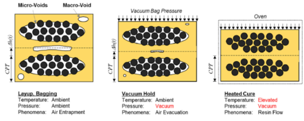
A theory of evolution of voids during the OoA prepreg consolidation process is shown in Figure 1 [7] including the lay-up, vacuum bagging and final cure stages. Initially, all the voids correspond to the evacuation channels created in the OoA prepreg, porosity between two adjacent layers and small voids in the space between two adjacent tows. During vacuum bagging and debulking, most of the interply voids are compressed while the evacuation channels remain open. Finally, during curing, the remaining voids are conduced to the evacuation channels that finally closed prior to the gelation of the resin producing an almost void-free laminate.
The void transport mechanisms presented previously are effective while the viscosity of the resin remains low. The time slot where viscosity remains at minimum values during the cure cycle is known as processing window. Once the curing reaction is triggered, the resin viscosity increases impeding the correct movement of the voids, entrapping them within the composite. Such voids can be finally classified as:
Intra-tow: Voids located within the fiber tows.
Inter-ply: Voids that are generated from entrapped air during stacking and lay-up operations.
Within resin: These voids are located within the resin pockets, due to the volatiles/moisture or entrapped air.
1.1 Objectives
The overall goal of this work was the investigation of void formation and transport mechanisms occurring during consolidation of laminates made up with out-of-autoclave prepregs using vacuum bag only conditions. Although IM7/M56 prepreg is commercially available, there is a consensus in the scientific literature regarding the lack of knowledge of the exact void forming and transport mechanisms in prepregs and especially in OoA prepregs. This is, in addition, more evident when dealing with new generations of prepregs containing interleaves (to enhance mechanical properties and interlaminar toughness) in the form of veils and particles that will act as barriers and obstacles to the normal transport of the voids.
X-ray tomography has been used as a powerful tool to inspect voids in composite materials produced using OoA prepregs. The ability of the technique to isolate and track individual voids allows a detailed characterization of the void population in terms of spatial distribution, shape and total content. We have developed novel experimental techniques to track individual voids during the curing of the prepreg for the first time in the literature and was considered as a very powerful technique to optimize composition of materials as well as the fiber architecture prior to complex and expensive experimental campaigns.
2 Materials and experimental techniques
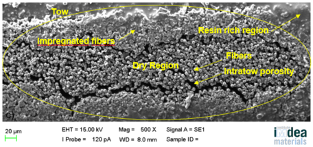
The composite panels used in this work were manufactured from unidirectional UD IM7/M56 prepregs (HexPly). The raw material is a commercially available prepreg and was supplied by Hexcel (Duxford, UK). IM7 is a PAN (Polyacrylonitrile)-based intermediate modulus carbon fiber for structural applications, while M56 is a resin specially designed by Hexcel to provide superior properties of the consolidated prepregs with low void content as a primary requirement for out-of-autoclave techniques. Figure 2 shows a scanning electron microscopy image of the cross section of unidirectional IM7/M56 prepreg clearly showing partially impregnated tows and resin rich regions. Fiber direction is perpendicular to the image.
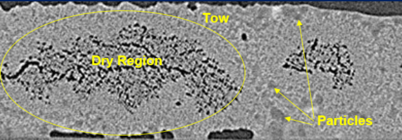
Reinforced prepregs contained either polyamide (PA) particles or veils at the interface with the intention to increase the interlaminar toughness and impact properties of the laminates. Figure 3 shows a Cross sections of the prepreg reinforced with particles (IM7/M56P) in the fresh state. Partially impregnated tows are visualized as well as the presence of particles surrounding fiber tows. In addition, the Figure 4 shows a 3D image of the fresh prepreg sample with surface veils (IM7/M56V).
Several quasi-isotropic laminates made of HexPly M56 prepregs of 400x400mm2 size containing 24 plies ([+45/0/-45/90]3s) were prepared using two procedures: standard hand lay-up (HLU) and automated fiber placement (AFP) which was carried out at the National Composite Center (NCC, UK).
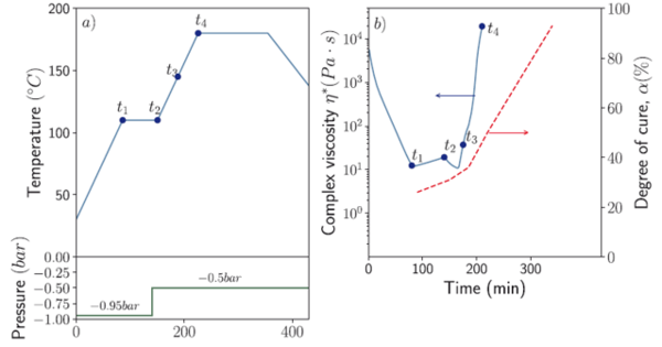
Some of the panels were partially cured to visualize the residual void content at a semicured state. The cure cycle of the individual panels was interrupted at the points of the cure cycle highlighted in Figure 5a. The dynamic viscosity evolution of the M56 neat epoxy resin across the cure cycle is shown in Figure 5b. The minimum viscosity level of ηmin ≈ 10Pa·s is obtained after point t2. The degree-of-cure α through the cure cycle is also plotted for comparison purposes. Point t1 was placed at the beginning of the first dwell to allow the resin viscosity to decrease, thus providing the necessary resin mobility to allow pore evacuation. Points t2 and t3 were selected according to the dynamic resin viscosity profile to study laminate microstructure during the period in which the resin viscosity remains at minimum value, called processing window. Lastly, point t4 was selected at the end of the second heating ramp to study the transition from low to high viscosity. A vacuum release to 0.5bar was applied at t2.
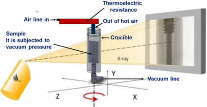
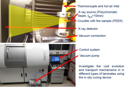
The main disadvantage of this procedure was that the sequentially cured laminates study had to be carried out using different panels. To better understand the porosity evolution and the transport mechanism in the CFRP laminate during the consolidation process an in-situ device was developed. For the design of the in-situ tomography curing system it was considered that the coupon should be processed under the same conditions than the large laminate, i.e. following the same temperature profile. In addition, the system should allow sample rotation to acquire the projections necessary for tomographic reconstruction and the furnace container should be transparent enough to avoid excessive X-ray absorption.
The samples for the in-situ experiments were fabricated by stacking unidirectional OoA standard and reinforced prepregs produced by HLU and AFP. Different stacking sequences were used to study their influence as well as the laminate thickness, and prepreg orientation with respect to the vacuum port.
The dimensions of each specimen were 10mm width by 20mm height and thicknesses from 1mm up to 6mm (depending on the lay-up configuration). Then, the miniaturized samples were bagged in a vacuum bag with a piece of breather tissue placed between the sample and the vacuum connection and cured following the specified cure cycle. The post curing (second dwell) was removed since the high resin viscosity prevent its flow after the second dwell. During curing a set of 10 to 20 tomograms were acquired for each coupon during the cure cycle. Figure 6 shows the sample configuration for the in-situ experiments and the 3D design of the crucible.
The in-situ system should be portable to take it and install it in any appropriate synchrotron beamline. Figure 7 shows a schematic representation of the design and its requirements. The system installed in the tomograph is shown in Figure 8.
Several experiments were carried out in lab tomography and in Synchrotron X-ray Tomography (SXCT) lines: TOMCAT beamline [8] of the Swiss Light Source (SLS), P05 beamline [9] of PETRA III at DESY and EDDI beamline [10] at BESSY II in Helmholtz-Zentrum Berlin.
3 Results
3.1 Sequential curing of OoA laminates
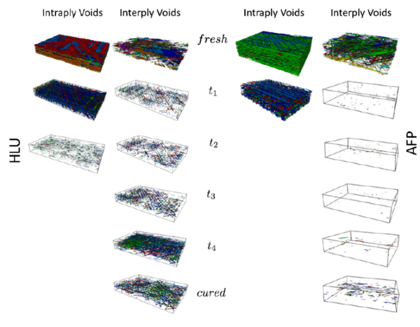
The coupons extracted from the center of the panels were inspected by XCT. The qualitative visualization of the evolution of the intraply and interply voids through the entire cure cycle, fresh, t1, t2, t3, t4 and fully cured conditions, in the HLU and AFP laminates is shown in Figure 9. Initially, most of the porosity was classified as intraply corresponding to the air evacuation channels. This porosity disappeared during the impregnation phase in the first dwell of the cure cycle up to point t2. The air path closure process was slightly more efficient in the case of the AFP laminates than HLU ones. In HLU, some voids were still present in the evacuation channels for t2 while in AFP laminates, they were completely filled by resin. As mentioned previously, the volume fraction of air paths was slightly lower in the AFP laminates than HLU and this could be possibly the reason for this effectiveness.
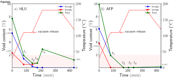
The evolution of the laminate porosity through the entire cure cycle in the HLU and AFP laminates is presented in Figure 10, including the interply, intraply and total porosity. Interply void removal in AFP laminates was highly effective and almost all voids disappeared after t1. In the case of HLU, interply void evolution was notably similar to the previous case but diverges in amplitude after the point t2 of the second heating ramp. This effect was previously attributed to a combination of temperature increase in the second ramp with a vacuum pressure partial release that may allow expansion of entrapped pores. In both cases, the final porosity after the cure cycle was not the minimum recorded which was located in the final first dwell t2.
Regarding the reinforced prepregs, the intratow void removal was also very effective in laminates with particles and evacuation channels were completely filled after point t1. However, the high value of the porosity detected by XCT is attributed to the high content of voids arrested by the presence of the particles that remained from the initial state and were not guided to the evacuation channels. In addition, the initial interply porosity in laminates interleaved with veils was higher than the laminate with particles and this effect was attributed to the open fiber network structure of the veil that is able to accommodate more air entrapments. However, after consolidation, all these values were considerably lower.
3.2 In-situ curing of OoA laminates
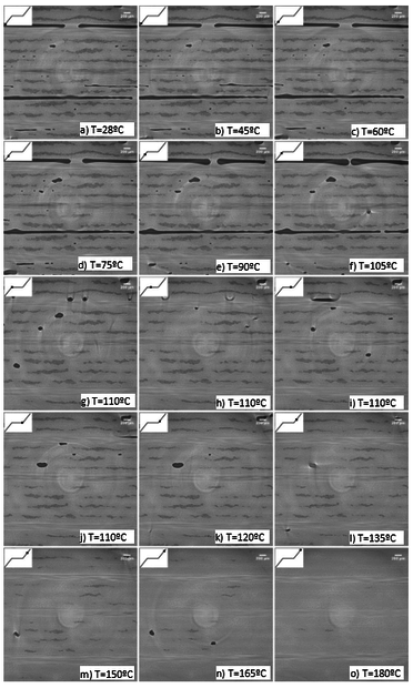
For the HLU IM7/M56 samples, the in-situ inspections were carried on samples with different stacking sequence, namely [90/90/90/90], [0/90/90/0], [+45/0/-45/90]s and [+45/0/-45/90]3s. Figure 11 shows cross sections of a thick laminate HLU IM7/M56 laminate with [+45/0/-45/90]3s stacking sequence, and the 90º direction is perpendicular to the image. The tomogram was acquired at the TOMCAT beamline. It shows that the dry tows do not begin to close until the first dwell and get fully infiltrated until the end of the second ramp. Even more, some microporosity remains in the tow. Interply porosity undergo the same evacuation mechanism as described before and some movement artifacts are observed during the first dwell when the resin viscosity is at its minimum values. The tows were the last to close, providing the necessary evacuation channels for the interply porosity. This indicates that the prepreg system and the kinetics of the resin are adequate, as well as the level of pre-impregnation in the prepreg.
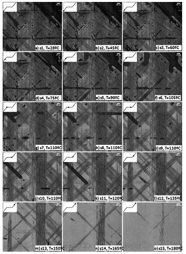
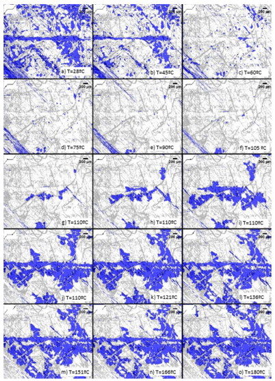
The projections of four plies and its interply porosity through-the-thickness direction and from the side of the same laminate is shown in Figure 12. Most changes of voids shape occur during the second half of the first ramp. The spread pores become more elongated following the directions of the tows and they were extracted during the first dwell and part of the second ramp. Figure 12 also suggests that largest pores are the more difficult to be evacuated. Additionally, it is also evident that the interply pores do not move at a constant speed within the laminate during the curing process even in the case that the resin viscosity is relatively constant during the dwell
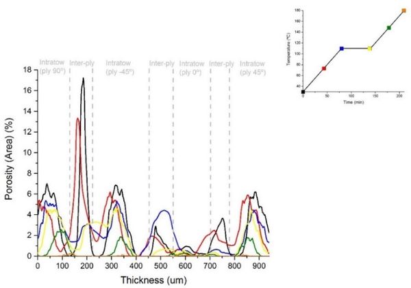
The total evacuated porosity value (defined as the percentage of pores evacuated with respect to the initial state) obtained by integration of the curves is shown in Figure 13.
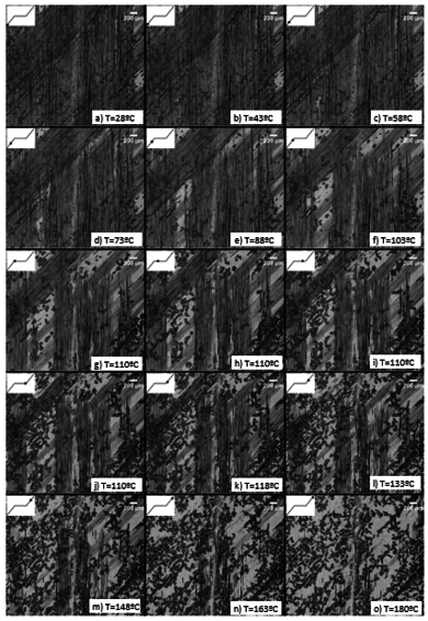
In reinforced AFP laminates, the particles, however, act as a bridge in the interface and preclude that the applied vacuum pressure reduces the pore volume. Even more, rather than migrating, the pores remain in their original position as the particles block their path and higher pressures are necessary to make them move in the interface. Pore movement towards the evacuation channels was hardly observed (Figure 14).
Since the veil system only have the interleaves at the surface, the infiltration mechanism of the dry tow is more similar to the material without interleaves. The interface between two plies, however, behave more similar to the system with particles. The veil located at the interface increase the sample surface thickness and form and interconnected network of non-straight fibers as it is shown in Figure 15. Due to the veil, the prepreg interface contain certain roughness which preclude stacking the material avoiding leaving porosity at the interfaces, even if it is done using AFP systems.
4 Conclusions
The analysis of void evolution using XCT of semicured laminates helped to understand the different mechanisms competition and provide very good estimations of the porosity evolution during the cure cycle. However, tracking individual voids was not permitted as the analysis was carried out between different samples cured at different stages of the cycle. To overcome these limitations and track the evolution of individual voids, a novel experimental device was designed and fabricated. This helped to investigate the in-situ evolution of voids during the consolidation of laminates processed by VBO using XCT. The applicability of the in-situ measurement system has been validated at the laboratory scale tomography and also by using synchrotron x-ray radiation working perfectly in both cases providing very valuable results. The mechanisms of void transport was totally consistent with the previous observations using semicured specimens. For the very first time, tracking the evolution of void transport was carried out in OoA prepregs, although the technique can be extrapolated easily to other ranges of temperatures and cure cycles.
Two different lay-up processes were used, hand lay-up (HLU) and Automated Fiber Placement (AFP). Porosity in cured HLU laminates was mainly interply very dependent on the layup configuration, debulking procedure and cure cycle. Cured specimens had low overall porosity value (≈ 2%), but strongly fluctuating at the local level. The evolution of the porosity observed in semicured samples was consistent with results found in the literature. Also, the thermal characterization of materials, prepregs and neat resin, was consistent with the cure cycle definition.
AFP laminates presented excellent final quality although the initial population of voids was significantly different which was attributed to tow slitting process during fiber deposition. The pathways in reinforced laminates worked perfectly, since the intratow porosity was completely removed after consolidation and the evacuation channels were almost closed at the end of the first dwell. However, AFP laminates containing thermoplastic particles presented high content of both, interply and intertow voids in the final cured stage.
In-situ experiments of curing process, the developed technical equipment and the methodology developed in this work is an excellent tool for the evaluation of new material systems were only small amount of material is necessary to study the curing process.
Acknowledgements
This research was supported by the AROOA project (Air removal in Out-of-Autoclave composites) from Hexcel Composites, Duxford, Cambridge CB22 4QB, United Kingdom. The authors wish to thank the National Composite Center NCC for the AFP panel preparation.
References
[1] Costa, M., Almeida, S. & Rezende, M., 2001. The Influence of Porosity on the Interlaminar Shear Strength of Carbon/Epoxy and Carbon/Bismaleimide Fabric Laminates. Compos Sci Technol, 61(14), 2101-2108.
[2] Liu, L., Zhang, B., Wang, D. & Wu, Z., 2006. Effects of Cure Cycles on Void Content and Mechanical Properties of Composite Laminates. COMPOS STRUCT, 73(3), 303-30.
[3] Kim, D., Centea, T. & Nutt, S., 2014. Out-time effects on cure kinetics and viscosity for an out-of-autoclave (OOA) prepreg: Modelling and monitoring. Compos Sci Technol, 100, 63–69.
[4] Grunenfelder, L., Centea, T., Hubert, P. & Nutt, S., 2013. Effect of room-temperature out-time on tow impregnation in an out-of-autoclave prepreg. Composites Part A, 45, 119–126.
[5] Naganuma, T., Naito, K., Kyono, J. & Kagawa, Y., 2009. Influence of prepreg conditions on the void occurrence and tensile properties of woven glass fiber-reinforced polyimide composites. Compos Sci Technol, 69, 2428–2433
[6] Grunenfelder, L. & Nutt, S., 2010. Void formation in composite prepregs – Effect of dissolved moisture. Compos Sci Technol, 70, 2304–2309.
[7] Centea, T., Grunenfelder, L. & Nutt, S., 2015. A review of out-of-autoclave prepregs – Material properties, process phenomena, and manufacturing considerations. Composites part A, 70, 132–154.
[8] Stampanoni, M. et al., 2006. Proc. SPIE, 6813, 63180M1.
[9] Haibel, A. et al., 2010. Micro- and nano-tomography at the GKSS Imaging Beamline at PETRA III Proc. SPIE. 7804, Developments in X-Ray Tomography VII, 78040B.
[10] EDDI, 2016. Helmholtz-Zentrum Berlin für Materialien und Energie. The 7T-MPW-EDDI beamline at BESSY II . Journal of large-scale research facilities, 2, A40.
Document information
Published on 13/10/21
Accepted on 06/10/21
Submitted on 14/09/21
Volume 05 - Comunicaciones Matcomp19 (2021), Issue Núm. 4 - Tesis doctorales presentadas al premio AEMAC a la mejor tesis., 2021
DOI: 10.23967/r.matcomp.2021.10.008
Licence: Other
Share this document
Keywords
claim authorship
Are you one of the authors of this document?
