Abstract
This paper discusses the response of the thermal insulation lining of rigid foam polyurethane (PU) derived from castor oil (Ricinus communis ) in heat conditions, based on dynamic climate approach. Liners have been widely used, because the coverage of buildings is responsible for the greatest absorption of heat by radiation, but the use of PU foam derived from this vegetal oil is unprecedented and has the advantage of being biodegradable and renewable. The hot wire parallel method provided the thermal conductivity value of the foam. The thermogravimetric analysis enabled the study of the foam decomposition and its lifetime by kinetic evaluation that involves the decomposition process. The PU foam thermal behavior analysis was performed by collecting experimental data of internal surface temperature measured by thermocouples and assessed by representative episode of the climatic fact. The results lead to the conclusion that the PU foam derived from castor oil can be applied to thermal insulation of roof systems and is an environmentally friendly material.
Keywords
Rigid foam polyurethane ; Ricinus communis ; Biodegradable ; Thermal behavior ; Heat insulation in roof systems
1. Introduction
The main goal of this paper discusses the PU foams thermal behavior when applied as thermal insulating lining in test cells in comparative study among four different situations, using the climate data analysis based on the concept of representative episode of the climatic fact. This paper also determines the conductivity coefficient of PU foam and its lifetime by the decomposition process kinetics.
The idea of using materials that assist in heat insulation had its beginning in 1940s, in an attempt to reduce expenditures on heating in countries with colder winters. However it was in the postwar society decades, between 1970s and 1980s, with oil prices rising, that the awareness of the need for reductions in energy consumption was more widespread. In Brazil, the market of thermal insulation products that integrates two or more building elements emerged in the 1980s. In recent years, the country has received a wide variety of products for heat insulation, which are used in roof systems and side locks, ceilings and floors (Moura, 2010 ).
Among the various applications of thermal insulation, linings have been widely used, since the coverage of buildings is responsible for the greatest absorption of heat by radiation (Teemusk and Mander, 2009 ). There are many materials used in thermal insulation, such as polystyrene, polyurethane, glass wool, rock and even pottery. The expanded polystyrene and polyurethane foam (from petroleum) are indicated for insulation at lower temperatures, but never above 80 °C or 90 °C, as they are susceptible to degradation by heat action. In the case of high temperatures, wool-based materials show better performance. Glass wool bears temperatures of approximately 250 °C; rock wool supports higher temperatures and the ceramic wool can bear temperatures above 1000 °C (FAO, 2010 ).
This work is important and innovative as it presents the potential use of rigid foam polyurethane (PU) derived from castor oil (Ricinus communis ) as a lining in the thermal behavior of roof systems in buildings as an alternative to materials currently marketed. This PU rigid foam can be considered a new type of material for “sustainable architecture” ( Preigaukas, 2011 ) because it originates from a plant easily cultivated and used in agriculture for soil nitrification, in the process of crop rotation. The cultivation of castor bean has created jobs in rural areas, with government support, since castor oil is used to produce biofuels (green oil) (Cangemi et al., 2010 ). When used as insulation the foam presents two fundamental properties: in case of fire no deadly gases are released, and PU foam is completely biodegradable (Cangemi et al., 2008 ).
This foam was developed by the Group of Analytical Chemistry and Polymer Technology (GQATP) at the Chemistry Institute of São Carlos, University of São Paulo, and is marketed by Cequil-Central Ind. Des. Polímeros Ltda. company located in the city of Araraquara, São Paulo, Brazil.
1.1. Dynamic climate approach: representative episode of the climatic fact
Monteiro (1973) stated that it is only possible to understand the pace of climate through joint analysis of climatological data obtained by units of chronological time, at least daily, which correspond to the representation of regional-scale atmospheric circulation, featuring the succession of atmospheric states. Through those rhythms, expressed by the climatic elements, it is possible to settle down episodes characterized and representative, through sequences of the weather, that represents more appropriately the climatic fact (Vecchia, 1997 ).
According to Vecchia (1997) , the dynamic approach that differentiates the episodes is the intensity and duration of each air mass which dominates over the place. In the case of the region of São Paulo, Brazil, the action of Polar Atlantic masses (mPA) or Tropical Atlantic masses (mTA) may be more or less vigorous, combined, of course, the process of heat gains by solar radiation.
The episodes should be characterized by their repercussion on the built space and, in particular, on the building envelope, defining their thermal and energy evaluation. The general evaluation of those envelopes affects the thermal sensations of the human organism improving situations of thermal stress. In that way, it is possible to characterize a representative episode of the climatic fact, in function of the thermal stress imposed on sensations of Human Comfort. It is of fundamental importance for this data collection to be sure to consider geographical factors modification (Vecchia, 1998 ).
After reviewing the episode actually representative of climate, one day may be chosen as representative of weather events, for visibility of the object of study (Givoni et al., 2001 ). Therefore, the correct use of climate dynamics depends on the viewing threads types of weather, from local responses collected through the daily and hourly variations of the elements of climate (surface measurements, through stations and meteorological stations) and images provided by meteorological satellites (Vecchia, 1998 ). The climate data analysis usually involves the annual patterns of the main climatic factors affecting human comfort and the thermal performace of buildings (Givoni, 1992 ). However, mere access to this database is not enough. It is necessary for the correct interpretation of values for the real understanding of atmospheric processes (Vecchia, 1997 ).
2. Experimental methods
2.1. The hot wire parallel method (HWPM)
The hot wire parallel method allows determining the three thermal properties simultaneously: thermal conductivity, thermal diffusivity and specific heat (Santos et al., 2004 ). Thermal conductivity is the property that establishes the level of working temperature of a material; it is an important parameter in problems involving heat transfer in steady state. Thermal diffusivity is a measurement of the speed at which heat propagates through the material and is important in problems involving unsteady state heat exchange. The specific heat is a thermodynamic quantity, important at high temperatures, and associated with energy consumption during heating (Santos, 2002 ).
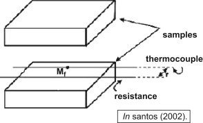
The test consists in adjusting the resistance and thermocouple in parallel so that they are at the center of the sample (Fig. 1 ) for the constant electric current that passes through the wire to release a steady amount of heat per time unit and length unit, which will propagate through the material.
|
|
|
Fig. 1. Drawing demonstrating the placement of the thermocouple and resistance in the HWPM. |
This test was standardized in 1978 by DIN 51046-Part 2. According to the norm, the thermal conductivity is calculated using only two points of the thermal transient. When a sentence of experimental thermal transient is considered, the thermal conductivity is calculated every two points and then a simple arithmetic mean of the calculated values is found. As the heat is provided by a thin electric resistance with a specific heat capacity, the sample is finite, there is a contact resistance between the wire and the sample, and the test has a minimum and a maximum time to be used in the calculation of thermal conductivity. In our test the calculation was performed by a software program created by Professor Wilson Nunes dos Santos, from the Engineering Materials Department, at the Federal University of São Carlos, São Paulo, Brazil.
2.2. Thermogravimetric analysis (TGA)
TGA is a technique in which the specimen to be analyzed is placed on scales and in an oven. The temperature is programmed and the equipment records the mass loss, obtaining all thermal decomposition (Claro Neto, 1997 ). In this work the samples of rigid polyurethane foam were analyzed with two objectives: to verify the decomposition steps and to determine its lifetime by analysis of kinetics of the process involved.
The study of decomposition steps allowed determining the useful temperature range of the material, i.e. with no change in its chemical stability. The study of the thermogravimetric curves, when performed at different heat ratios, allows for a kinetic evaluation by means of a mathematical analysis using the Ozawa–Flynn–Wall model (ASTM, 2005 ).
For the thermogravimetric analysis, the SDT Q 600 model from TA Instruments was used. The objective of the TGA is to study the decomposition of the foam at different temperatures.
2.3. PU foam thermal insulation
The PU foam composed of castor oil and a pre-polymer based on MDI (diphenylmethane diisocyanate) was obtained by mixing the components in the mass proportion of 0.7 polyol to 1.0 pre-polymer with mechanical agitation for 20 s; it was then poured into the proper mold. After polymerization PU foam of 40 kg/m⊃3; density was obtained. For each plate 210 g polyol and 300 g pre-polymer were used, totaling 510 g of material on each plate. For the preparation of the plates utilized in the linings of test cells 02 and 04 a cast iron of 0.50×0.50×0.03 m3 inner dimensions was used. The final weight of around 400 g and 0.03 m thickness with an area of 0.25 m⊃2;. The final thickness of the plates was set based on the materials sold as thermal insulators, which have thicknesses between 25 mm and 50 mm (ISAR, 2010 ).
2.4. Thermal behavior analysis of the PU foam derived from castor oil
2.4.1. Test cells: location and characteristics
São Carlos is located in a region known as tropical or intertropical zone. The climate is predominantly tropical (EMBRAPA, 2008 ), marked by the alternation of two seasons: dry season with dry and warm winters (April to September) and rainy season with hot and humid summers (October to March).
The comparative experimental study comprised among four cover systems, as follows:
- Test Cell 01: asbestos cement tile without ceramic slab and PU foam lining from castor oil.
- Test Cell 02: asbestos cement tile and PU foam lining from castor oil.
- Test Cell 03: asbestos cement tile and ceramic slab.
- Test Cell 04: asbestos cement tile, ceramic slab and PU foam lining from castor oil.
The test cells are brick masonry constructions of fired clay over “raft” of reinforced concrete with a standardized size, differing only in the roof system. Spaces are built with appropriate scale so that they can maintain the linearity of the temperature data collected close to the real situation. This linearity of the measurements would not be achieved if scale models were used instead of test cells (Vecchia, 2003 ).
The test cells were designed to ensure equivalence to a real situation in data acquisition. Their constructive characteristics are similar and they were arranged on the ground so that there was no shadow of the other cells in relation to the apparent path of the sun, and they had the same conditions of equality before any other weather event.
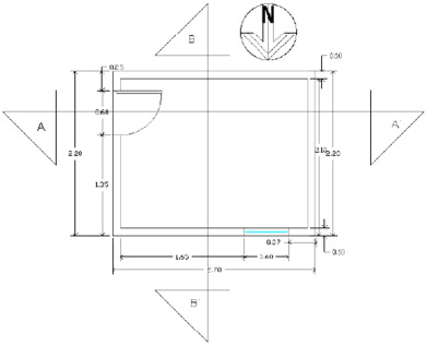
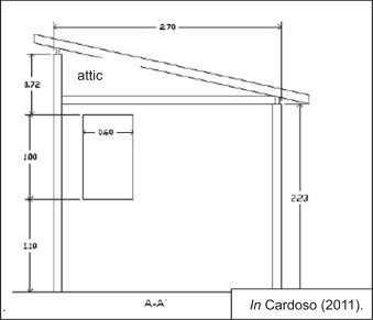
The four test cells have internal dimension of 2.20 m×2.70 m (Fig. 2 ) and ceiling height of 2.23 m. The roof is tilted up to approximately 5% (Fig. 3 ). Each cell has a standard port of 2.10 m×0.60 m size facade facing east and a 1.0 m×0.70 m window facing north. Doors and windows are made of Tetra Pak® plasterboard packaging.
|
|
|
Fig. 2. Test cell floor plan (schematic drawing). |
|
|
|
Fig. 3. Test cells A–A′ section (schematic drawing). |
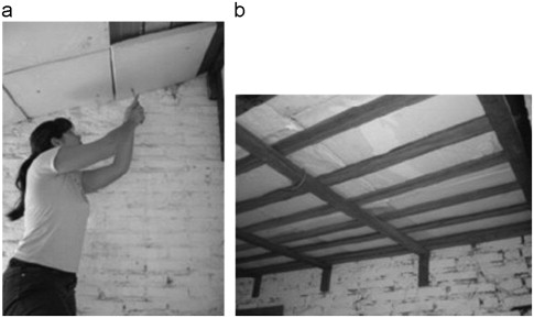
The roof systems are similar, except for the absence or not of the component items (Table 1 ). Test cell 01 has only the asbestos cement roof. Test cell 02 has an asbestos cement roof and the PU foam lining derived from castor oil set up above a wooden structure in a grid (Fig. 4 b). There is an attic between the asbestos cement roof and the PU foam lining (Fig. 3 ). Cell 03 has an asbestos cement roof and ceramic slab. There is also an attic between the asbestos cement roof and ceramic slab (Fig. 3 ). Test cell 04 is the most complete roof system because it has an asbestos cement roof, ceramic slab and PU foam lining. In Cell 04, the ceramic slab was made following the roof slope, i.e., 0.30 m away from it, forming an air mattress. The PU foam lining was installed on ceramic slabs inner surface by screws (Fig. 4 a).
| Component items | Thickness (cm) |
|---|---|
| Asbestos cement roof | 0.4 |
| PU foam lining | 3.0 |
| Ceramic slab | 10.0 |
⁎ By the author.
|
|
|
Fig. 4. (a) Placement of the PU plates in cell 04 and (b) PU foam lining in test cell 02. |
The test cells adopted for the research are located in the experimental plot of the Laboratory Building (LCC) of the Department of Architecture and Urban Planning, Engineering School of São Carlos, University of São Paulo, located in São Carlos, São Paulo, Brazil (Cardoso, 2011 ).
2.4.2. Equipment for data collection in the experimental plot
The equipment of the station is provided by Campbell Scientific Inc. company, responsible for the collection and storage of meteorological data, such as solar radiation, temperature and relative humidity, wind speed and direction, atmospheric pressure and rainfall. Other equipment, such as a 12 V rechargeable battery, solar panel and the CR10X datalogger keeps the station working.
The data from the test cells were collected by measurements of surface temperatures, and by means of 2×24 AWG type T (copper-constantin) thermocouples, with measurements at intervals of 30 min taken on the inner surface of the materials, which appear as the last components of the roof system for each test cell. The thermocouples were connected to the multiplexer and the data were stored on the CR10X datalogger. After this storage, the data were transferred online by modem to the Laboratory Building (LCC) computer through specific software PC208W.
The experimental plot located at the Department of Architecture and Urban Planning, Engineering School of São Carlos, University of São Paulo, holds an automatic weather station and the test cells used in the research, with the proper equipment installed for the acquisition of relevant data.
2.4.3. Installation of thermocouples in the test cells
The thermocouples were placed in each test cell in accordance with the elements that compose each roof system, as the research would evaluate the thermal performance of PU foam derived from castor oil in a comparative study of four roof systems. The aim was to record the temperature inside the surface of the last element of the roof system:
- TEST CELL 01: In this case the thermocouple was placed on the inner surface of the tiles.
- TEST CELL 02: The thermocouple was installed on the inner surface of a lining plate.
- TEST CELL 03: The ceramic slab received the thermocouple on its inner surface.
- TEST CELL 04: Thermocouple was also placed on the inner surface of a lining plate.
2.4.4. Climate analysis
According to Monteiro (1973) , the climate of São Carlos, São Paulo, Brazil, is controlled by equatorial and tropical air masses, setting the state of transition between a distinctly dry season with warm and dry winters (April to September) and a rainy season with hot and humid summers (October to March). The dry season is characterized by low precipitation, low cloud cover, low relative humidity, and lower average temperatures when compared with the rainy season, primarily from Tropical Atlantic and Polar Atlantic air masses in the region. The rainy season has high average temperatures with abundant rainfall and high relative humidity with predominant Equatorial Continental air mass.
The data collected are related to the climatic rhythm from January to April. We chose a representative day with typical conditions of heat, as maximum solar radiation, i.e., the sky remained clear, with low cloud cover, taking the values of the Normais Climatológicas 1960–1991 (Ministério da Agricultura e Reforma Agrária, 1992 ) as a reference.
3. Results
3.1. Hot wire parallel method (HWPM)
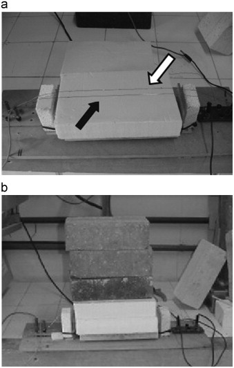
In the HWPM samples measuring 0.05×0.23×0.14 m3 and density of 37.0 kg/m3 were used. The samples were placed in the apparatus to ensure the greatest possible contact. The resistance used was KANTHAL 6.4900 Ω/m, 0.07 m positioned at the edge of the sample across the width, and a K-type thermocouple in parallel with 0.015 m resistance (Fig. 5 a). Some pressure was applied to the set (Fig. 5 b) to ensure greater contact between the samples and the hot wire.
|
|
|
Fig. 5. (a) Placement of the resistance (white arrow) and thermocouple (black arrow). (b) Final adjustment of the PU foam sample. |
Although 15 min would be enough for the test, we chose a period of 30 min to ensure a more accurate result. In this test we used an electric current of 1.1 A, and the set remained at room temperature. The results for rigid polyurethane foam samples derived from castor oil were:
- THERMAL CONDUCTIVITY: 0.045 W/m K
- SPECIFIC HEAT: 4607.15 J/kg K
- THERMAL DIFFUSIVITY: 2.65×10⁻⁷ m⊃2;/s
- CORRELATION COEFFICIENT: 0.99998
- NUMBER OF TESTS: 5
According to parameters followed by Professor Wilson Nunes dos Santos, the rigid foam polyurethane derived from castor oil can also be classified as an insulating material (0.01–0.05 W/m K).
3.2. Thermogravimetric analysis (TGA)
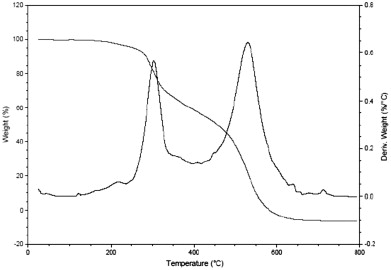
Fig. 6 shows the thermogravimetric curve of PU foam derived from castor oil at a heating rate of 10 °C/min and air flow of 100 mL/min.
|
|
|
Fig. 6. TGA curves for PU foam, 10 °C/min, in air atmosphere of 100 mL/min. |
As can be seen in Fig. 6 , the overall process of decomposition occurs in two stages, starting at 170 °C. According to Claro Neto (1997) , the first stage is associated with a breaking in the urethanes chains, and then in the ester bonds. The PU foam derived from castor oil does not suffer any type of decomposition at temperatures below 170 °C.
A mathematical treatment performed by the TA Instruments company software (Fly-Wall-Ozawa Model) provided the results shown in Table 2 . We can infer that it takes the polymer approximately 14 years to achieve this conversion rate at constant temperature of 81 °C.
| Temperatura (°C) | Temperature (K) | Lifetime (h) |
|---|---|---|
| 30.0 | 303.1 | 5.05×10⁹ |
| 47.0 | 320.1 | 1.01×10⁸ |
| 64.0 | 337.1 | 2.990.000 |
| 81.0 | 354.1 | 124.000 |
| 98.0 | 371.1 | 6900 |
| 115.0 | 388.1 | 494 |
| 132.0 | 405.1 | 44.1 |
| 149.0 | 422.1 | 4.78 |
| 166.0 | 439.1 | 0.617 |
| 183.0 | 456.1 | 0.0926 |
| 200.0 | 473.1 | 0.0159 |
⁎ By the author.
The results show that at the temperature at which the material will be exposed as thermal lining insulating there occurs no decomposition, guaranteeing that this liner can be used in construction.
3.3. The thermal behavior of the PU foam insulator
São Carlos' region has a dry season with warm and dry winter, and rainy season with hot and humid summer. Due to setbacks with the data collection system of test cells, the period of study was delimited from January to April.
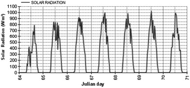
Within this period a climatic episode was chosen which has weather with heat conditions, with low cloud cover, no rainfall, since the foam thermal behavior was made facing the heat. Therefore, it was chosen the representative episode of the climate fact among March 6th, 2010 to March 12th, 2010, i.e, among 65 to 71 days of the Julian year (the term “day or Julian year” is not commonly used, only in situations that need to ascertain the exact day on which the data were collected, whereas the Gregorian calendar which uses a flexible system of leap year and can be adjusted to close to the stations as needed, ultimately cause confusion and uncertainty in climate data).
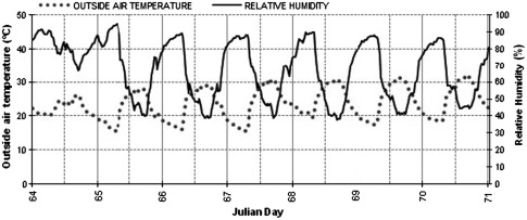
Fig. 7 ; Fig. 8 show data collected by the automatic station, related to representative episode for studied climate fact.
|
|
|
Fig. 7. Chart of solar radiation—March 6th, 2010 to March 12th, 2010. |
|
|
|
Fig. 8. Chart of outside air temperature and air relative humidity—March 6th, 2010 to March 12th, 2010. |
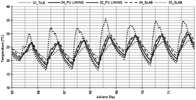
The influence of the same episode in internal surface temperatures of the test cells was recorded by the thermocouples installed in each area, and it is shown in Fig. 9 .
|
|
|
Fig. 9. Chart of internal surface temperatures—March 6th, 2010 to March 12th, 2010. |
Looking at the weather charts for the chosen episode, taking into account the behavior of climate variables during this period, it can be observed that there was passage of a cold front which starts to tropicalize from March 07th, allowing the analysis of rigid polyurethane foam thermal behavior in response to hot conditions. This is true because from March 07th, the outside air temperature (Fig. 8 ) increases relative to the previous day, and it remains high, due to the influence of solar radiation, since there is little cloud cover and rainfall does not occur. As the study object is not the complete climate analysis, the cold front passage through the São Carlos' region was not analyzed.
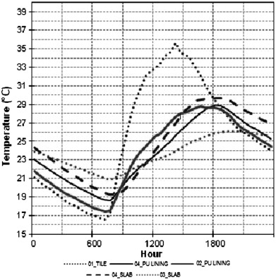
In the comparative study among the four test cells, March 9th, 2010 was chosen as a representative day of hot conditions that occur in summer–autumn transition, Fig. 10 and Table 3 . For this day the maximum value for global radiation was 994 W/m2 (13:30 p.m) and the maximum value for outside air temperature was 30.86 °C (3:00 p.m).
|
|
|
Fig. 10. Chart of internal surface temperatures—March 9th, 2010. |
| Test cell | Temperature maximum (°C) | Temperature minimum (°C) |
|---|---|---|
| Test cell 01 (Tile) | 35,61 (2 p.m) | 16,58 (7 a.m) |
| Test cell 02 | 28,78 (4:30 p.m) | 17,56 (6:30 a.m) |
| (PU lining) | ||
| Test cell 03 (Slab) | 26,02 (6:30 p.m) | 20,87 (7:30 a.m) |
| Test cell 04 (Slab) | 29,72 (6:30 p.m) | 19,23 (7:30 a.m) |
| Test cell 04 | 28,94 (6 p.m) | 18,61(7:30 a.m) |
| (PU lining) | ||
⁎ By the author.
In test cell 01 the radiation in the tiles is rapidly transmitted to the inside as heat due to the low thermal inertia of the tiles and the fact that they do not have thermal insulation properties. The roof system of test cell 02 acts as an attic between the roof and the horizontal ceiling sloped PU foam, parallel to the floor. In this situation the attic helps the lining insulation. Fig. 10 and Table 3 show that there is a difference of 6.83 °C between the maximum temperature reached in cell 01 (35.61 °C at 2:00 p.m) and that reached in cell 02 (28.78 °C at 4:30 p.m). However, due to the thickness of the plates, the thermal inertia is low. Test cell 03 is the roof system widely used in buildings. There is an attic too. In this case the ceramic slab is not a good insulator, but it is thicker than the foam lining, showing greater thermal inertia. In the case of the PU lining in test cell 04 was expected a lower value for its internal surface temperature, because this cell is more complete than the other cells used in the study. However, in this case there is no an attic, only a space of 0.30 m between the asbestos cement roof and ceramic slab, thus the internal surface temperature of PU lining in cell 04 was higher than the internal surface temperature of ceramic slab in test cell 03.
Comparing the PU foam lining maximum temperature of test cells 02 and 04, it can be said that the difference is not in the value each one reached, but in the time they take to reach maximum temperature.
Analyzing the results it was found that the characteristic of insulating polyurethane foam lining reduces the heat input during both day and night. Another factor that helped the thermal insulation was the presence of the attic. The confined air inside the attic requires longer heating power to transmit heat. The air mattress in cell 04 also helps the insulation. The thermal mass can help heat insulation when combined with other insulating devices.
4. Conclusions
According to the hot wire parallel method, the PU foam derived from castor oil can be considered a very insulating material. The thermogravimetric analysis showed that the decomposition of the foam begins at approximately 170 °C, i.e., the PU foam has higher resistance to degradation by heat, but it needs other tests to confirm that can be recommended for insulation at temperatures above 80 °C. Therefore, the estimated lifetime of castor foam at constant temperature of 81 °C is approximately 14 years. Other tests, however, must be performed to complement the characterization of the material.
Concerning the comparative study of the thermal behavior of the foam applied by means of plates, it was possible to conclude that the foam can reduce the heat exchange between outdoor and indoor environments, decreasing approximately 6 °C of the maximum internal surface temperature. This feature combined with other auxiliary devices in thermal insulation can ensure greater efficiency to the heat exchange reduction.
Acknowledgements
The authors are grateful to CNPq, FAPESP. We gratefully acknowledged Dr. Wilson Nunes dos Santos (Materials Engineering Department/Federal University of São Carlos); and the Laboratory Building staff for their technical assistance in the experiments.
References
- ASTM E 698–05, 2005 ASTM E 698–05, 2005. Standard test method for arrhenius kinetic constants for thermally unstable materials using differential scanning calorimetry and the flynn/wall/ozawa method.
- Cangemi et al., 2008 J.M. Cangemi, et al.; Biodegradation of polyurethane derived from castor oil; Polímeros: Ciência e Tecnologia, 18 (3) (2008), pp. 201–206
- Cangemi et al., 2010 J.M. Cangemi, A.M. Santos, S. Claro Neto; A Revolução Verde da Mamona; Química Nova na Escola, 32 (1) (2010), pp. 3–8
- Cardoso, 2011 Cardoso, G., 2011. Characterization of rigid polyurethane foam (PU) extracted from: castor oil (Ricinus communis ) for building insulation. VDM Verlag Dr. Müller. Saarbrücken, Germany, pp. 84.
- Claro Neto, 1997 Claro Neto, S., 1997. Caracterizações físico-químicas de um poliuretano derivado de óleo de mamona utilizado para implantes ósseos. 1997. 127 f. Tese (Doutorado)—Instituto de Química de São Carlos, Universidade de São Paulo, São Carlos.
- EMBRAPA, 2008 EMBRAPA, 2008. Dados meteorológicos. Homepage: 〈http://www.cppse.embrapa.br/080servicos/dados-meteorologicos〉 .
- FAO, 2010 FAO, 2010. Corporate document repository. Homepage: 〈http://www.fao.org/docrep/006/y5013e/y5013e08.htm#TopOfPage〉 .
- Givoni, 1992 B. Givoni; Comfort, climate analysis and building design guidelines; Energy and Buildings, 18 (1992), pp. 11–23
- Givoni et al., 2001 Givoni, B., et al., 2001. Predicting thermal performance of occupied houses. Proceedings of the 18th Conference on Passive and Low Energy Architecture, PLEA 2001, Florianopolis, Brazil.
- ISAR, 2010 ISAR, 2010. Isolamentos térmicos. Homepage:〈http://www.isar.com.br〉 .
- Ministério da Agricultura e Reforma Agrária, 1992 Ministério da Agricultura e Reforma Agrária, 1992. Normais climatológicas (1961–1990).
- Monteiro, 1973 Monteiro, C.A.F., 1973. A dinâmica climática e as chuvas no Estado de São Paulo: estudo geográfico sobre a forma de atlas. Instituto de Geografia-USP, São Paulo.
- Moura, 2010 Moura, E., 2010. Conforto ambiental. Revista Téchne. Homepage: 〈http://www.revistatechne.com.br/engenharia-civil/127/imprime64533.asp〉 .
- Preigaukas, 2011 Preigaukas, E., 2011. Climate responsive building design principles in the South Australia. Homepage: 〈http://www.emilis.sa.on.net/〉 .
- Santos, 2002 W.N. Santos; O método de fio quente: técnica em paralelo e técnica de superfície (The hot wire method: the hot wire parallel technique and the hot wire surface technique); Cerâmica, 48 (306) (2002), pp. 86–91
- Santos et al., 2004 W.N. Santos, et al.; Hot wire technique in the determination of thermal properties of polymers; Polímeros, 14 (5) (2004), pp. 354–359
- Teemusk and Mander, 2009 A. Teemusk, Ü. Mander; Greenroof potential to reduce temperature fluctuations of a roof membrane: a case study from Estonia; Building and Environment, 44 (2009), pp. 643–650
- Vecchia, 1997 Vecchia, F.A.S., 1997. Clima e ambiente construído: a abordagem dinâmica aplicada ao conforto humano. 329 f. Tese (Doutorado)—Faculdade de Filosofia Letras e Ciências Humanas. Universidade de São Paulo, São Paulo.
- Vecchia, 1998 Vecchia, F.A.S., 1998. Climate and built environment. Applied dynamic approach to the characteriztion of representive episodes of climate. Environmentally friendly cities, Proceedings of PLEA'99, Lisbon, Portugal.
- Vecchia, 2003 Vecchia, F.A.S., 2003. Comportamento térmico de sistema de cobertura. Eternit S.A., São Paulo,01, pp. 74.
Document information
Published on 12/05/17
Submitted on 12/05/17
Licence: Other
Share this document
Keywords
claim authorship
Are you one of the authors of this document?
