Abstract
Recently, reinforced concrete beams strengthened with carbon fiber reinforced polymers (CFRP) have been widespread. The objective of this research is to calculate the shear strength capacity increment of reinforced concrete beams strengthened by CFRP strips. The ABAQUS software was used to construct a model of the finite elements for beam simulation. Six beams were generated in ABAQUS software, two were control beams and the remaining four were reinforced by varying CFRP strips. All beams had the same rectangular cross-section geometry and length. The obtain results showed that CFRP can significantly increase the shear capacity of the beam. And the highest load and deflection is a little affected by the CFRP strips orientation. This study can proposes a more economical way for existing structures to improve the carrying capacity.
Key words: Reinforced Concrete (RC) beam, Carbon Fiber-Reinforced Polymer (CFRP), externally bonded, shear strength
1. Introduction
Recently, the maintenance and upgrading of existing structures are increased due to the new standards, environmental impact, and the end of building design life. In this case, strengthening the existing reinforced concrete structures is one of main components of the current construction industry. In order to ensure ductile failure mode, the bending strength of reinforced concrete beam must be less than the shear strength. Therefore, strengthening the reinforced concrete beam is mainly to enhance its shear resistance. The application of external carbon fiber reinforced polymer(CFRP) bonding is increasingly adopted by these transformation schemes, and is generally recognized by the current guidelines and design specifications [1,2]. In recent years, many scholars have studied the external bonding of CFRP. Toutanji et al. [3] used different layers of carbon fiber cloth to reinforce the simply-supported beams, and the bearing capacity of the beams increased as the number of carbon fiber tape layers increased. Khalifa and Nanni [4] tested six reinforced concrete beams with a T-shaped cross section. The results show that the externally bonded CFRP can significantly improve the shear capacity of the beam. Bousselham [5] tested samples of reinforced concrete beams reinforced with CFRP end anchors. The results show that the increase in average shear capacity was as high as 41 percent for reinforced beams using EB U-jacket strips with end anchorage. Obaidat et al. [6] used ABAQUS to establish a nonlinear 3D model to study the shear characteristics of CFRP strengthened beams, and verified the model using the data obtained from the experiment. The results show that the length and direction of CFRP have a significant effect on the performance of the reinforced beams. Farghal [7] studied the effect of shear reinforcement ratio on the performance of reinforced beams. In this paper, the commercial finite element software ABAQUS was used to establish a finite element model to simulate the characteristics of the beam, so as to study the shear strength of reinforced concrete beams with and without CFRP strips. Also, the failure mode of the beams and the influence of CFRP with different fiber orientation on the shear strength were also discussed in this research. This article can proposes a new, more economical and easy-to-use reinforcement method for existing structures in the future construction industry, thereby improving the carrying capacity of existing structures.
2. Numerical design of specimens
2.1 Design of Specimens
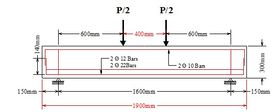
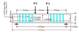
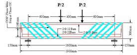
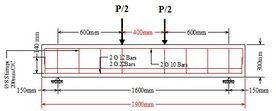
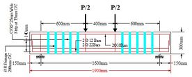
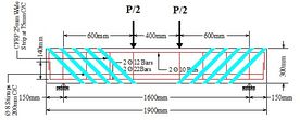
In this study, six specimens were designed and divided into two groups, each containing three specimens: W1, W2, W3 and S1, S2, S3 (Figure 1). The specimens of series W were without shear stirrups and the specimens of series S were with shear stirrups. All specimens have the same rectangular cross-section shapes. All specimens have the same length and shear span to depth ratio, mm, and cross-section size mm mm. The concrete strength is C30 and the longitudinal reinforcement is a hot rolled HRB400 grade steel bar. The mean compressive strength of concrete was 28 N/mm². Two diameter of 22 mm bars and two diameter of 14 bars were used in this experiment as longitudinal tension reinforcement and two diameter of 12 bars as longitudinal compression reinforcement of the cross-section to support shear failure. The two diameter of 8 Hot-Rolled Bars (HRB335) were used for Stirrups. The W1 specimen was not reinforced by CFRP strips and named the control beam. The W2 and S2 specimens were reinforced with a single CFRP ply attached in a continuous U-warp with a fiber direction perpendicular to the axis of the beam (90°) and the W3 and S3 was reinforced in the same way as W2 only CFRP rotated by 45°.
2.2 ACI 440 model
The parameters including flexural capacity, maximum crack, and deflection of specimens were calculated due to Chinese code GB50010-2010 [8]. RC beam can be express the total shear strength , at a given section, as
|
|
(1) |
where is the concrete shear strength, is the shear strength influence of CFRP, and is the shear strength of transverse steel
|
|
(2) |
|
|
(3) |
where is the number of Legs of Stirrup and is spacing between Stirrups.
This shear strength contribution was identified by many researchers [9–18]. In this study, ACI 440 was used to calculate the CFRP contribution of shear strength. The suggested CFRP contribution of shear strength in ACI 440 [2] is supported on the study present in [4,19] and is given by
|
|
(4) |
|
|
(5) |
|
|
(6) |
where is the number of layer of the CFRP strip/sheet applied
|
|
(7) |
|
|
(8) |
|
|
(9) |
|
|
(10) |
|
|
(11) |
The parameters of beams are shown in Table 1.
| Beam | h(mm) | b(mm) | h0(mm) | a(mm) | a/d(mm) | Flexural capacity (KN/m) |
Shear capacity (KN) |
Maximum crack width(mm) |
Maximum deflection (mm) |
|---|---|---|---|---|---|---|---|---|---|
| W1 | 300 | 150 | 264 | 2.27 | 600 | 165.91 | 42.6 | 0.36 | 4.17 |
| W2 | 264 | 2.27 | 165.91 | 80.85 | 0.36 | 4.17 | |||
| W3 | 264 | 2.27 | 165.91 | 96.7 | 0.36 | 4.17 | |||
| W4 | 256 | 2.34 | 159 | 101.76 | 0.386 | 4.24 | |||
| W5 | 256 | 2.34 | 159 | 140 | 0.386 | 4.24 | |||
| W6 | 256 | 2.34 | 159 | 155.8 | 0.386 | 4.24 |
3. Methodology finite element modeling
3.1 Material properties and constitutive models
Concrete
Concrete acts like a plastic material when exposed to a state of multiaxial stress. For these reasons, the behavior of concrete has been established in this research and that is why the use of concrete plasticity damaged models was used in ABAQUS. Concrete C30 was used in this research. Due to the Chinese code GB50010-2010, the cube strength of C30 concrete after 28 days of 20.1 MPa. The following other properties also described for concrete in Table 2.
| Property name | concrete |
| Compressive strength | 20.1MPa |
| Mean compressive strength | 28MPa |
| Secant modulus of elasticity | 3MPa |
| Mean tensile strength | 2.01MPa |
| Fracture energy | 0.07N/mm |
| Poisson’s ratio | 0.2 |
Steel reinforcing
In this design, steel was sculptured in concrete as fully embedded, bilinear elastic, and perfectly plastic material. The modeled tension reinforcement cross-section area was 78.54mm², modeled compression reinforcement cross-section area was 493.23mm². The compression and tension yield stress used was 456 MPa, the possion’s ratio was taken 0.3 and the elasticity of modulus was 200GPa. Beams has shear stirrups, and its stirrups were also constructed using the same constitutional relationship. No interaction between transverse and longitudinal steel was considered, as an alternative both were embedded in concrete. Whereas the ratio of Poisson and the yield elastic modulus for stirrups were the same as the longitudinal steel and the yield stress was 382MPa.
CFRP Modeled
Carbon fiber-reinforced polymer (CFRP) is a composite materials that could be made of fibers oriented in a different direction. Design as linear elastic orthotropic materials should, therefore, be used in ABAQUS. The CFRP band module was 0.5mm thick and 25mm wide. The carbon fiber-reinforced polymer (CFRP) was therefore modeled as a linear elastic materials. The CFRP strips tensile strength was 3.792GPa, the modulus of elasticity was 227GPa and the ratio of Poisson was 0.3. The concrete and CFRP interface materials were modeled using a cohesive zone model. The 1mm epoxy layer was formed by portioning the shear zone of the beams, both sides, and bottom of the beams like a U-jacketing.
3.2 Interaction
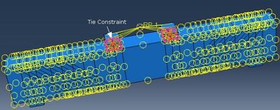
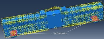
Three types of interactions have been defined in the current model. The interaction between reinforcement and concrete surface, load and support plate surface, concrete beam and CFRP. The interaction between the support plate and the concrete beam as well as the load plate and the concrete beam were tie constraint interaction to make two surface tie together permanently, and use same tie constraint interaction between loading plate and concrete beam as shown in Figure 2.
| |
| |
| Figure 2. Tie constraint interaction between the concrete beam and loading/support plate | |
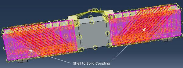
The second constraint used shell to solid coupling constraint between CFRP strips and concrete beam as shown in Figure 3. The interaction between the concrete beam and CFRP corresponding to the bond constraint interface was defined. Make sure the two surfaces are permanently bonded together.
|
| Figure 3. Shell and solid coupling constraint between CFRP strips and concrete beam |
3.3 Boundary condition
As shown in Figure 4, the present model included two support reactions, which were pinned support and roller support, boundary conditions applied to both reactions. The pinned support that resists both horizontal and vertical forces and also resists rotational force. This was accomplished by constraining all degrees of freedom translational, such as . The other was roller support, the boundary condition of which was defined only by constraining translation in 1 and 2 and the support itself permits horizontal translation. Escaping from the concentrated deformation at the aid, it was important to apply the aid to a small area as shown in Figure 3. In the initial step, there were two boundary conditions.
In the recent model, the two load plates were modeled for two load area which was 400mm apart from each other and couple both plates by coupling constraint. When the load applied the beam start deflection downward and due to the calculated maximum deflection of the beam was 4.24mm shown in section 3.4.2. For this research model taken , because the beam maximum deflection is 4.24mm for accuracy of results taken deflection more than the calculated maximum deflection and the negative sign show deflection is downward. Applied displacement control as a ramp, with linear increments. Hence the controlled displacement takes more time is compared to force control. It detentions in an excellent way the distortion and can go smooth under the highest load.

|
| Figure 4. Pinned and roller support reaction |
4. Analysis and results
4.1 Initiation of cracks
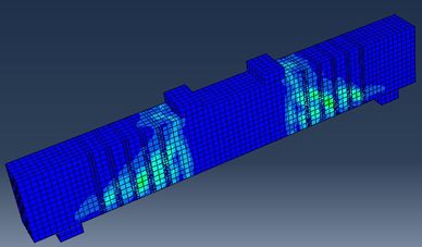
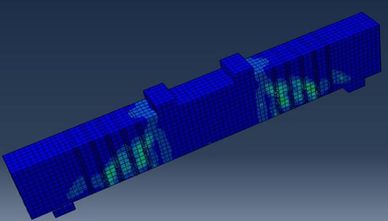
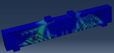
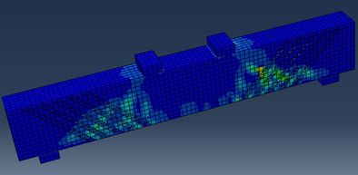
The crack patterns of reinforced concrete beams strengthened with CFRP were quite different from those of control beams. Compared with the control beams there were more cracks with marrow spacing. The reason is that the beams strengthened with CFRP have greater shear strength in shear span, which leads to narrow cracks. Therefore, the beams revealed another critical crack in that area as well. However, Compared with the control beam, the critical crack in the shear span has been identified. Compared with the reinforced concrete control beam, the path of using CFRP can make the cracks get narrower dispersion. The shear crack patterns of beams strengthened with CFRP are shown in Figures 5 and 6.
| |
| (a) Beam without stirrups | |
| |
| (b) Beam with stirrups | |
| Figure 5. Shear cracks pattern of CFRP strengthened beams by 90° | |
| |
| (a) Beam without stirrups | |
| |
| (b) Beam with stirrups | |
| Figure 6. Shear cracks pattern of CFRP strengthened beams by 45° | |
4.2 Damage of beam
In this study, we measured both compression and tensile damage. The damage parameters describe the degree of damage and degradation of the reinforced CFRP materials and the elastic stiffness of the concrete when the reinforced concrete beam was bent under four-point load.
For CFRP, the damage degree of the reinforcement materials and concrete was different. The main reason for different damage was the different in tensile strength. Compared with ordinary reinforced concrete beam, CFRP strengthened beams have higher tensile strength, so CFRP strengthened beams have almost no damage.
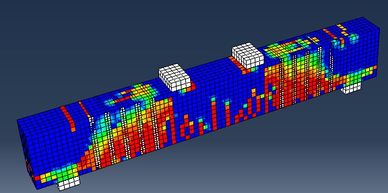
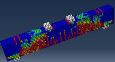
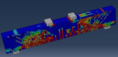
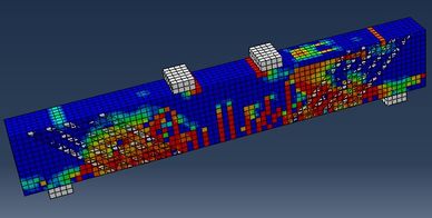
Figures 7 and 8 show how the CFRP materials and concrete damaged due to tension. The tensile damaged of concrete of the beams strengthened with CFRP by 90 °were shown in Figure 7 and beams strengthened with CFRP by 45° were damaged due to tension as shown in Figure 8. Hence, tensile damage is as well an important parameter to classify the likely failure mode of CFRP strengthened reinforced concrete beams. A statement made from tensile damage shows the possibility of shear cracks and small micro flexural cracks propagation. Shear cracks to propagate inclined in tension zone through the neutral axis and till to compression zone and then crushing of concrete occurs in the compression zone.
| |
| (a) Beam without stirrups | |
| |
| (b) Beam with stirrups | |
| Figure 7. Tensile damage for beams strengthened with CFRP by 90° | |
| |
| (a) Beam without stirrups | |
| |
| (b) Beam with stirrups | |
| Figure 8. Tensile damage for beams strengthened with CFRP by 45° | |
4.3 Load deflection relationship
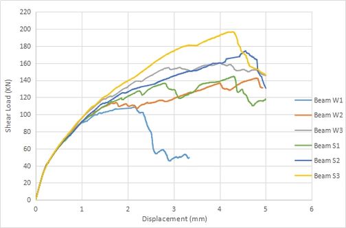
The beam which was strengthened with CFRP strips is shown little delay the initiation of crack because the beam strengthened at shear span. The beam W2 and S2 were strengthened with CFRP strips by 90°, which was mostly covered the crack initiation area due to this its needs more load to initiation of cracks compare with the beam W1 and S1. Same like that, the beam W3 and S3 were strengthened with CFRP by 45°, which was covered more the crack initiation area of shear span compare with W2 and S2 and CFRP strip pasting by 45°in the opposite direction of cracks initiation of the beam so that’s why required more load for initiation of cracks.
As shown in Figure 9, the ultimate shear strength of control beams with stirrups and without stirrups is 108.935KN and 143.824KN respectively. The ultimate shear capacity of CERP strengthened beams (W2, S2) were 142.38KN and 174.3321KN. The beams (W3, S3) were 160.881KN and 196.24KN. Compared with the control reinforced concrete beam (W),the shear load ultimate capacity of the reinforced concrete beam (W2) has increased by 23.5%, and the reinforced concrete beam strengthened with CFRP has increased by 32.3%. It seems The CFRP strips increase of 17.5% ultimate shear load capacity of RC beam with stirrups (S2) is compared to the control RC beam with stirrups (S1) and (S3) seen to increase 26.8% compared to control RC beam (S1).Since a shear crack propagates diagonally the direction of the CFRP can influence a strengthened beam’s behavior. Two orientations are studied 90°and 45°. It’s clear that when the orientation angle was 45°the strengthened beam has taken more static load. It’s remarkable to note that the shear load capacity of beam W3 was increased by 8.9 % compared to beam W2 and beam S3 was increased by 9.2 % compared to beam S2. This shows that the enactment of a strengthened RC beam with CFRP strips affected by the orientation of CFRP strips.
|
| Figure 9. Load deflection cures for all designed beams |
4.4 Mechanism of failure
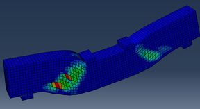
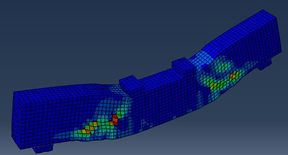
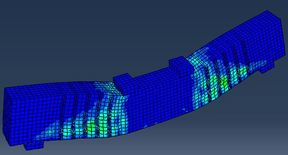
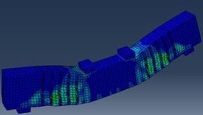
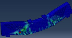
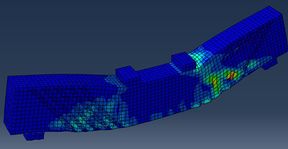
The mean shear failure of the strengthened beam with CFRP is debonding of CFRP strips from the beam. When the beams generate cracks in shear span, debonding will occur. Reinforced concrete beams also exhibit other forms of failure, such as shear stirrups yielding and concrete crushing under compression. The failure mechanisms of control beams with stirrups and without stirrups were both predictable. The mechanisms of failure were examined established on displacement control as the case for cracks distribution rather than force control. The mode of failure of control RC beams and CFRP strengthened beam as shown in Figure 10. The concrete strain of all reinforced concrete beams under load is about 0.0062. This strain is greater than the ultimate compressive strain of concrete. Figures 4 and 8 clearly shows the crushing failure of concrete.
|
|
| Beam W1 | Beam S1 |
|
|
| Beam W2 | Beam S2 |
|
|
| Beam W3 | Beam S3 |
| Figure 10. Strengthened beam and control beam mode of failure | |
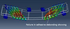
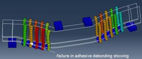
The detected mode of failure in control beams was tensile steel yielding and concrete crushing in the zone of compression under the points of loading, and the detected failure mode in CFRP strengthened beams were yielding of steel, debonding of the CFRP strips and crushing of concrete in compression zone beneath the point of loading, as shown in Figure 11.
|
|
| Figure 11. Shear span CFRP debonding failure | |
As shown in the above Figures 7 and 8, failure in adhesive showing debonding and vertical crack initiation in shear span starting in tension face of the beam through the neutral axis and then reached to compression zone which causes concrete crushing in the zone of compression beneath the points of loading.
5. Conclusion
For this research, a new model of shear strength was developed to precisely quantify the shear strength in RC beams increases due to strengthened with CFRP strips. The finite element results indicated that it is useful to strengthen RC beams with CFRP strips. The conclusion are as following:
(1) U-jacket strips provided with the strengthened RC beams which spectacle less or more ductile behavior at a high level of loading up to a load level just before failure.
(2) There are three failure modes of the control beam, the first is the brittle failure mode, the second is the shear cracking, and the third is the crushing of the concrete below the load point in the compression zone.
(3) The ultimate shear strength of the beams strengthened with CFRP were higher than the beams without CFRP. It shows that the externally bonded CFRP can significantly improve the shear capacity of the beam.
(4) In the present research, the RC beams without shear stirrups strengthened with CFRP strips, a large increase was obtained in the shear strength capacity compared with the RC beams with stirrups strengthened with CFRP.
(5) The highest load and deflection is a little affected by the CFRP strips orientation. CFRP strips orientation for 45°, a large increase in load-carrying capacity is gained compared to 90°.
List of symbols
The meanings of the symbols in this study are as follow:
| : Area of CFRP strip |
| : Effective stress of CFRP strip |
| : Depth of CFRP strip |
| : Spacing between CFRP strips |
| : The thickness of CFRP strip |
| : Tensile modulus of elasticity of carbon fiber reinforcement |
| : Design rapture strain of CFRP |
| : Modification factor applied to to account for concrete strength |
| : Modification factor applied to to account for Wrapping Scheme |
| : Bond length |
| : Mean characteristic value of axial compressive strength of concrete |
| : Depth of CFRP strip |
| : Is the factor that accounts for the influence of loading type and shear span to depth ratio on the shear strength of beams |
| : The effective depth of the section |
| : Mean characteristic value of compressive strength of ordinary steel reinforcement |
| : Area of shear stirrups (shear steel) |
| : Width of reinforcement section |
| : Depth of section |
| : The effective depth of the section |
| : Shear span length |
Data availability
The raw/processed data required to reproduce these findings cannot be shared at this time as the data also form part of an ongoing study.
Conflicts of Interest
The authors declare that they have no conflicts of interest.
Funding Statement
This study was supported by the Fundamental Research Funds for the Central Universities CHD (300102281206).
References
[1] Maruyama K. JSCE recommendations for upgrading of concrete structures with use of continuous fiber sheets. FRP Composites in Civil Engineering, 2001.
[2] 400 ACI C. Guide for the design and construction of externally bonded FRP systems for strengthening concrete structures. American Concrete Institute, 2004.
[3] Toutanji H.A., El-Korchi T., Katz R.N., Leatherman G.L. Behaviour of carbon fiber reinforced cement composites in direct tension. Cem. Concr. Res., 23(3):618–626, 1993.
[4] Khalifa A., Nanni A. Improving shear capacity of RC T-section beams using CFRP composites. Cem. Concr. Compos., 22(3):165-174, 2000.
[5] Bousselham O.C.A. Behavior of reinforced concrete T-beams strengthened in shear with carbon fiber-reinforced polymer - An experimental study. Aci Struct. J., 103(3):339–347, 2006.
[6] Obaidat Y.T., Heyden S., Dahlblom O. The effect of CFRP and CFRP / concrete interface models when modelling retrofitted RC beams with FEM. Compos. Struct., 92(6):1391–1398, 2010.
[7] Farghal O.A. Fatigue behavior of RC T-beams strengthened in shear with CFRP strips. Ain Shams Eng. J., 5(3):667–680, 2014.
[8] GB50010-2010: Code for design of concrete structures. Ministry of Housing and Urban-Rural Development of the People's Republic of China, 2015.
[9] Wight J.K., MacGregor J.G. Reinforced concrete: Mechanics and design. 6th ed., Prentice Hall, p. 1176, 2011.
[10] Bazant P.Z., Kim J.K.. Size effect in shear failure of longitudinally reinforced beams. ACI Journal, 81(5):456-468, 1984.
[11] Bazant P.Z., Yu Q. Designing against size effect on shear strength of reinforced concrete beams without stirrups. J. Struct. Eng., 131(12):1877-1885, 2005.
[12] Arslan G. Cracking shear strength of RC slender beams without stirrups. J. Civ. Eng. Manag., 14(3):177-182, 2008.
[13] Arslan G. Shear strength of reinforced concrete beams with stirrups. J. Mater. Struct., 41:113-122, 2008.
[14] Bukhari I.A., Ahmad S. Evaluation of shear strength of high-strength concrete beams without stirrups. Arab. J. Sci. Eng., 33(2B):321-336, 2007.
[15] Song J., Kang W.H. Probabilistic shear strength models for reinforced concrete beams without shear reinforcement. Struct. Eng. Mech., 31(1):15-38, 2010.
[16] Kuo W.W., Cheng T.J., Hwang S.J. Force transfer mechanism and shear strength of reinforced concrete beams. J. Eng. Struct., 32:1537-1546, 2012.
[17] Zararis P.D. Shear strength and minimum shear reinforcement of reinforced concrete slender beams. ACI Struct. J., 100(2):203-214, 2003.
[18] Tureyen A.K., Frosch R.J. Concrete strength: another perspective. ACI Struct. J., 100(5):609-610, 2003.
[19] Khalifa A., Gold W.J., Nanni A., Aziz A.M.I. Contribution of externally bonded FRP to shear capacity of RC flexural members. J. Compos. Constr., 2(4):195–202, 1998.
Document information
Published on 30/08/21
Accepted on 16/08/21
Submitted on 22/06/21
Volume 37, Issue 3, 2021
DOI: 10.23967/j.rimni.2021.08.001
Licence: CC BY-NC-SA license
Share this document
claim authorship
Are you one of the authors of this document?
