1 Introduction
The modern automobile industry is constantly facing with new requirements associated to recyclable, fuel-efficient, safety, and low-emission vehicles. In order to give answers to these issues, vehicle manufacturers have been focusing in developing lightweight advanced materials in order to reduce the overall vehicle mass and decrease the negative environmental impacts during use phase. Although, reducing the overall weight of modern automobiles with a decrease processing time and cost, ensuring the affordability of the vehicles is a challenge. Affordability is essential since it will allow for larger portion of the vehicle manufacturers to adopt specific light weighting solutions [1, 2].
Sheet moulding compound (SMC), is a widely used process of the automotive sector, due to its capability to produce thermoset based components with discontinuous glass fibre reinforced composites with an acceptable specific stiffness and strength, combined with a cost-efficient manufacturing process and high formability. To continue to enhance material properties of SMC products and to meet the increasing interest in this material class, different approaches recently focused on combining this process with carbon fibres, particular in aerospace applications. However, the combination of oriented, continuous carbon fibres prepregs with traditional SMC represents a new technology approach for automobile production and automotive engineering [3-6].
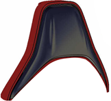
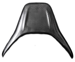
Therefore, with this hybrid composite technology would be possible to guarantee a very high productivity, excellent part reproducibility, cost efficiency, and produce lighter/stronger components with complex geometries and integrated functions. With this knowledge, the main objective of this work is to show the technical viability of a traditional SMC process, hybridized with carbon fibre prepreg, in a demonstrative car seat structure (Figure 1).
Mechanical properties were analysed and quantified by lap shear adhesion and impact tests. The visual aspect of the final prototype was also studied in this research work.
2
Materials and Methods
2.1 Raw materials and manufacturing procedures
A commercially available carbon prepreg, with trade name Pyrofil™, and an epoxy matrix were used to produce the headrest structure.
Unidirectional carbon prepreg (30 wt. % of resin content) was used as reinforcement and woven fabric (40 wt. % of resin content) was the last layer added to give a good visual finishing.
The prototype was produced in two phases:
- 1. Prepreg compression moulding (PCM) manufacturing process
- 2. Hybrid composite manufacture
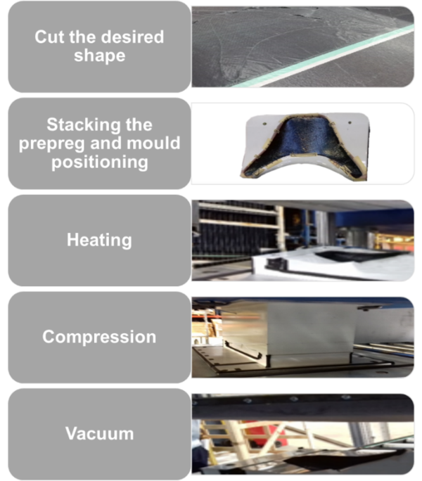
In the first phase, the prepreg layers were stacked up and formed to a pre-shape, which was similar to the final one. This phase can be summarized in the following steps (Figure 2):
- 1. Cut the desired shape - Cutting the layers of prepreg, from the prepreg rolls, to the desired shape and orientation;
- 2. Stacking the prepreg and mould positioning - Stacking the prepreg layers to the desired combination and positioning on the proper position on the mould;
- 3. Heating - Has a purpose to soften the material for the pressing step;
- 4. Compression - The different prepreg layers are compressed together, cooled down and shapped to a close to the final shape;
- 5. Vacuum - A vacuum membrane is lowered on top of the post-compression PCM part and, after membrane is fully lowered, it is applied vacuum to the PCM, where the void concentration/percentage is reduced and the PCM parts are demoulded.
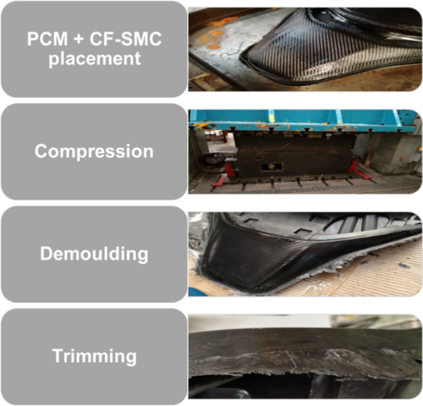
After obtaining the PCM, the carbon fibre sheet moulding compound (CF-SMC) composites are combined together to obtain the desired hybrid headrest structure. This 2nd phase can be synthesised in the subsequent steps (Figure 3):
- 1. PCM + CF-SMC placement - Placement PCM headrest structure on the mould and the CF-SMC charges;
- 2. Compression - The upper and lower moulds are set to a specific temperature that allows for the proper CF-SMC flow within the mould, fill the part correctly and ensure the bonding of the two composite materials. The temperature combined with pressure and time, will ensure the cure of the resin and give the part its final shape;
- 3. Demoulding - Demoulding the compound in its final shape and in an advanced cure state;
- 4. Trimming - After demoulding the part there are some sharp edges and excess material that needs trimming afterwards in order to be able to deliver a finished part.
During the manufacturing process, there are a few defects that can occur and that should be taken into consideration when optimizing the parameters, mould special characteristics, shapes, material placement and quantities.
2.2 Tests procedures
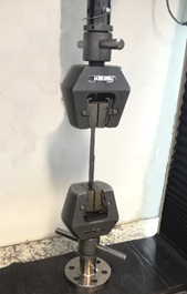
In order to test and validate the resistance of the bonding areas, it were used the principles according to the test procedure described in standard ASTM D 5868-01 [7]. Three specimens with an overlay of 25 x 25 mm, for each bonding condition (Table 1), were tested at a constant loading rate of 1,3 mm/min. These tests were carried out in a universal mechanical testing machine (INSTRON 4208), equipped with a 100 kN load cell (Figure 4). All specimens were previously conditioned at 23°C/50% RH for 24 hours before testing.
| Type | Standard | Hybrid |
| Material combination | CF-SMC | CF-SMC + CF-prepregs |
Visual inspection of the prototype has been performed to ensure that it was free from the unacceptable defects according to ASTM D 2563-08, beaning the most relevant visual defects are porosity, wash and wrinkles [8].
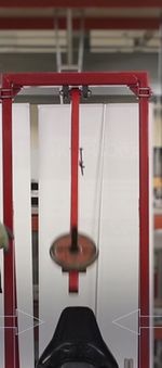
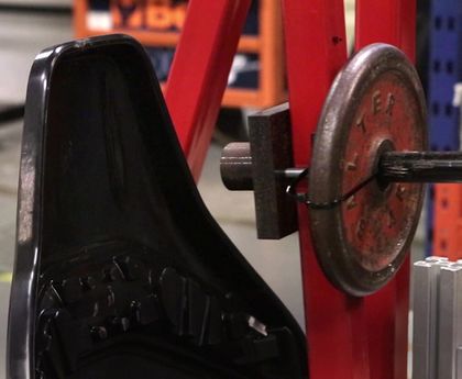
Impact tests were performed in the prototype (Figure 5) to ensure that it follows the requirements of ECE-R17 and FMVSS202a [9, 10].
3 Experimental Results and Discussion
3.1 Data test results
Lap-shear test results, in terms of maximum strength (Fmax), maximum deflection (dmax) and maximum stress (σmax) are summarized in Table 2. Presented values represent the average values obtained for 3 specimens of each trial formulation and correspondent standard deviations.
| Standard | Hybrid | |
| Fmax [N] | 1485.28 ± 104.07 | 4096.69 ± 159.99 |
| dmax[mm] | 4.01 ± 0.98 | 1.39 ± 0.19 |
| σmax[N/mm2] | 1.28 ± 0.04 | 6.73 ± 1.21 |
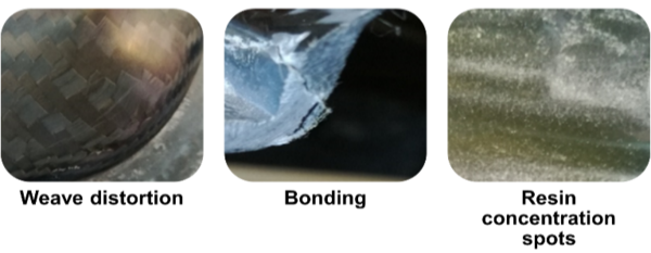
The detected visual defects in the final prototype are shown in Figure 6.
In the impact tests, it was verified that the headrest have accomplish the standard requirements.
3.2 Analysis and discussion
The hybrid solution leads to an increase on peak load of approximately 176%, when compared with the standard solution. The hybrid materials lead to a lower axial displacement (-65%), which may indicate a higher specific stiffness around the bonded area (Figure 7).

|

| ||
| Standard | Hybrid |
It was observed that most relevant visual defects indicated in the ASTM D 2563-08 were not detected in the prototype. Although it was observed three defects:
- 1. Weave distortion - Most likely due to wrong CF-SMC charges placement and poor PCM shape design.
- 2. Bonding – Probably several parameters lead to this defect, such as setup of the machines, CF-SMC placement, PCM shape or fault on the compression area.
- 3. Resin concentration spots – Is mainly caused by the CF-SMC placement and flow.
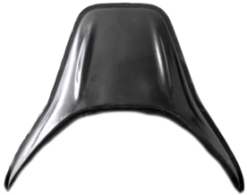
Overall, it can be considered that the visual aspect requirement it was achieved. In Figure 8 can be observed the standard and the hybrid headrest structure. Although the visual quality of the developed prototype can be improved.
|
| |
| Standard
|
Hybrid
| |
After the impact tests it was observed that the standard solutions and the hybrid prototype were undamaged. Although, the hybrid solution is 25% lighter that the standard one but is three times more expensive due to the new materials used and an increase on the more processes that need to take place to produce the hybrid prototype.
4 Conclusions
There is a huge world concern with the environment sustainability and European legislation has been changing tending to restrict levels of pollution in industry and the mobility of automobiles. With this knowledge, automotive industry has been absorbed the lighter advanced composite materials and technologies from aeronautic sector to improve the performance of the components.
Experiments were performed in order to demonstrate the technical viability of a traditional SMC process hybridized with Carbon fibre prepreg reinforcements (typical aeronautical solution), in a demonstrative car seat structure. The SMC process presented within this study enabled the manufacturing of hybrid carbon fibre SMC sheets based on two-steps. The developed solution was compared with the conventional one. The key findings of the developed testing programme are as follows:
- Properties in terms of maximum adhesion force as well as failure evolution were investigated. The developed hybrid solution leads, in general, to significant increase of the adhesion properties and a higher specific stiffness around the bonded area;
- Few visual defects that were observed are likely related to the mould, which causes small distortions on the twill. It can be considered that the visual aspect requirements were achieved;
- Both standard and hybrid headrest structures accomplish the impact requirements;
- The hybrid solution is 25% lighter and 3 times more expensive that the standard one.
Therefore, with the results obtained in this research is possible to verify that the development of the combination of SMC and pre-impregnated, orientated carbon fibre fabrics is auspicious referring to an improvement of adhesion properties. Besides, this technology promises optimised lightweight and load-bearing properties in connection with complex shapes and design freedom. However, for automotive applications there does not exist a one special SMC hybrid technology. Consequently, each material combination has to be developed and adapted to the requirements for each particular application.
However, for now, the process is very time consuming due to the preparation required per each moulding. The life-cycle cost and the visual aspect benefits are expected to compensate the slightly higher manufacturing cost in relation to the original part due to the cost of the prepreg material. Although there are many open questions regarding this innovative, hybrid SMC technology. Further research will be needed to in terms of process automation to ensure the required process quality.
Acknowledgements
This work was performed under the AEROCAR project, co-financed by the Interreg Sudoe Program through the European Regional Development Fund (ERDF).
“Authors gratefully acknowledge the funding of Project NORTE-01-0145-FEDER-000022 - SciTech - Science and Technology for Competitive and Sustainable Industries, cofinanced by Programa Operacional Regional do Norte (NORTE2020), through Fundo Europeu de Desenvolvimento Regional (FEDER)”.
References
[1] D. Mayer, T. Bein, H. Buff, B. Gotz, O. Schwarzhaupt, and D. Spancken, "Enhanced lightweight design by composites - Results of the EU project ENLIGHT," Journal of Reinforced Plastics and Composites, Article 37, no. 19, pp. 1217-1224. (2018).
[2] V. K. Soo, P. Compston, and M. Doolan, "Interaction between New Car Design and Recycling Impact on Life Cycle Assessment," Procedia CIRP, 29, pp. 426-431. (2015).
[3] S. B. Visweswaraiah, M. Selezneva, L. Lessard, and P. Hubert, "Mechanical characterisation and modelling of randomly oriented strand architecture and their hybrids - A general review," Journal of Reinforced Plastics and Composites, Review 37, no. 8, pp. 548-580. (2018).
[4] A. Trauth, K. A. Weidenmann, and W. Altenhof, "Puncture properties of a hybrid continuous-discontinuous sheet moulding compound for structural applications," Composites Part B-Engineering, Article 158, pp. 46-54. (2019).
[5] J. Wulfsberg, A. Herrmann, G. Ziegmann, G. Lonsdorfer, N. Stoss, and M. Fette, "Combination of carbon fibre sheet moulding compound and prepreg compression moulding in aerospace industry," in 11th International Conference on Technology of Plasticity, Ictp 2014, 81, T. Ishikawa and K. I. Mori, Eds. (Procedia Engineering, Amsterdam: Elsevier Science Bv, pp. 1601-1607. (2014).
[6] W. White Salmon, A. L. SpA, and I. Sant’Agata Bolognese, "Lamborghini “forged composite®” technology for the suspension arms of the sesto elemento,". (2011).
[7] ASTM D5868-01(2014), Standard Test Method for Lap Shear Adhesion for Fiber Reinforced Plastic (FRP) Bonding, ASTM International, West Conshohocken, PA. (2014).
[8] ASTM D2563-08(2015), Standard Practice for Classifying Visual Defects in Glass-Reinforced Plastic Laminate Parts, ASTM International, West Conshohocken, PA. (2015).
[9] Agreement Concerning the Adoption of Uniform Technical Prescriptions for Wheeled Vehicles, Uniform Provisions Concerning the Approval of Vehicles with Regard to the Seats, their Anchorages and Any Head Restraints. (2014).
[10] H. A. Kaleto, H. W. Mangum, P. Lee, and M. Schick, "Overview of Federal Motor Vehicle Safety Standard (FMVSS) 202A-Head Restraints: Methodology and Equipment for the Dynamic Test," SAE Technical Paper 0148-7191. (2007).
Document information
Published on 21/06/22
Accepted on 18/06/22
Submitted on 18/06/22
Volume 05 - Comunicaciones Matcomp19 (2021), Issue Núm. 3 - Procesos de Fabricación – Materiales Funcionales., 2022
DOI: 10.23967/r.matcomp.2022.06.022
Licence: Other
Share this document
Keywords
claim authorship
Are you one of the authors of this document?
