Abstract
The aim of this work is to carry out numerical simulations in the time domain of seakeeping problems taking into account internal flow in tanks, including sloshing. To this aim, a Smooth Particle Hydrodynamics (SPH) solver for simulating internal flows in tanks is coupled in the time domain to a Finite Element Method (FEM) diffraction–radiation solver developed for seakeeping problems. Validations are carried out comparing against available experimental data. Good agreement between obtained numerical results and experimental data is found.
1. Introduction
There are a series of marine operations and/or navigation conditions in which the coupling between internal flow in tanks and seakeeping dynamics can be crucial in configuring the global dynamic response of the vessel. The assessment of such coupling effects may be thus extremely important in order to estimate the viability of certain operations as well as the risks associated to specific load conditions during navigation. Such navigation conditions and/or operations include: those carried out by offshore vessels, equipped with anti-roll tanks, commonly in the oil&gas industry, consisting of deploying piping systems, cables, drilling equipment, etc. (see e.g. Neves et al., 2009); those referred to the offloading of oil or Liquefied natural gas (LNG) from an floating production storage and offloading (FPSO) platform, bunkering vessel or a floating LNG (FLNG) to a shuttle, regular vessel or LNG carrier, respectively, in side-by-side configurations (see e.g. Watai et al., 2015); the transport in partially filled tanks of such LNG or its storage in FLNG tanks (see Zhao et al., 2011, for a review on FLNG vessels hydrodynamics).
Due to their large economic cost and much larger penalties in case of any unexpected problem, the planning of above mentioned operations or the definition of filling level thresholds of tanks, requires a deep understanding of the coupled dynamics between the vessel and the internal flows. In order to achieve such understanding it is important to notice that while the external dynamics can be usually resolved in relatively large time scales, the internal dynamics may incorporate violent sloshing flows, which requires resolving complex free-surface dynamics with much shorter time scales. In addition, when wave excitation is present, for low wave amplitudes, the motions are usually linear with amplitude and frequency while for moderate or large wave amplitudes, the response can be extremely nonlinear. For these reasons, in order to simultaneously resolve the seakeeping and internal flow dynamics, different types of solvers are typically used for each of them. For instance, Zhao et al. (2014a) use a frequency domain linear boundary element method (BEM) approach to obtain hydrodynamic coefficients and wave forces, which is coupled in the time–domain with a nonlinear potential solver for the internal dynamics. Another example is the commonly cited reference of Kim et al. (2007) who also resort to frequency domain calculations and resolve the internal flow modeled with Euler equations, with a finite difference scheme. With the same technique for ship motions Li et al. (2012) solved the internal flows with the widespread used open-source volume of fluid (VOF) based solver OpenFOAM.
Regarding the numerical method traditionally adopted for seakeeping simulation, the boundary element method (BEM) has dominated over others like finite element method (FEM). We might find the reason in the fact that most of the computational effort is spent in solving the Laplace equation. Then it might look like BEM offers a lower computational effort. However, Cai et al. (1998) carried out a heuristic study regarding the computational effort required for solving the Laplace equation by BEM and FEM. This study concluded that for a similar three-dimensional problem and a discretization size, the number of unknowns of BEM and FEM are O(N2) and O(N3), respectively, being N the number of unknowns needed in one dimension to achieve the desired discretization. But the computational costs are O(N4) and O(N3) respectively. Therefore, while BEM might be more efficient for problems with low number of unknowns, FEM becomes more efficient respect to BEM as the number of unknowns increases. Considering that computational capabilities continuously increases, so does the complexity of problems to be undertaken, and the number of unknowns required. Hence FEM become more efficient than BEM.
Time–domain diffraction–radiation solvers based on the Finite Element Method (FEM) have been previously used (see Ma and Yan, 2009, Serván-Camas and García-Espinosa, 2013). Their capability to naturally incorporate non-linearities is larger than those time–domain solvers based on frequency domain pre-calculations such as the ones used by Kim et al. (2007), Li et al. (2012), or Zhao et al. (2014a). Those solvers have been successfully used with coupled mooring models (Ma and Yan, 2009), in side-by-side (Yan and Ma, 2011) or even in multi-body configurations (Serván-Camas and García-Espinosa, 2013).
FEM based solvers have, however, to the authors’ knowledge, not yet been used to model coupled sloshing and ship motions. Due to the onset of violent sloshing, internal dynamics can be extremely complex and therefore computationally expensive to resolve. In this context, Smoothed Particle Hydrodynamics (SPH) solvers can be a competitive option since, on the one hand, they are able to cope with extremely non-linear and fragmented free-surface flows, and on the other hand, they are easily parallelized with cost competitive graphic card processing units.
SPH solvers have been successfully used in the past for solving coupled dynamics of single degree of freedom angular motion coupled sloshing problems (Bouscasse et al., 2014a, 2014b, Bulian et al., 2010) and their parallelization with GPUs has been subject of significant recent attention (see e.g. Crespo et al. 2011; Domingues et al. 2013; Herault et al. 2010; Nishiura et al. 2015). In this paper, the internal flow dynamics is solved using AquaGPUSPH (Cercós-Pita, 2015) and the seakeeping dynamics is solved with SeaFEM (Serván-Camas and García-Espinosa, 2013). Both solvers, AquaGPUSPH and SeaFEM, have been developed by the authors.
The paper is organized as follows: section 2 introduces the internal flow and wave diffraction–radiation solvers; section 3 describes the rigid body dynamics solver; section 4 focuses on the details of the coupling algorithm, as well as in the communication between solvers; section 5 presents a validation study comparing the results obtained in this work against experimental data available for three different case scenarios; finally, section 6 provides the conclusions of this work.
2. Internal flow and seakeeping solvers
Let’s mention that the seakeeping and internal flow solvers are independently developed, compiled, and distributed software. On one hand, the seakeeping solver is SeaFEM, a potential FEM time domain suite of tools for seakeeping simulation [1] developed by the International Center of Numerical Methods in Engineering (CIMNE) [2], in collaboration with CompassIS [1]. On the other hand, the internal flow solver is AQUAgpusph, an open-source 3D SPH solver, accelerated with OpenCL in order to run on GPUs, developed by the Model Basin Research Group [3] of the Technical University of Madrid.
2.1. Internal flow solver: AQUAgpusph
2.1.1. General.
AQUAgpusph (Cercós-Pita, 2015) is a recently released free 3D SPH solver, licensed under GPLv3, and accelerated with OpenCL. AQUAgpusph source code along with developers' documentation, a gallery of images, videos, validation cases and a news blog, is available for downloading at [4]. AQUAgpusph validation is thoroughly documented in Cercós-Pita (2015), where it was used to model the sloshing flows inside a Lead-cooled Fast Nuclear Reactor during an earthquake, focusing on the evaluation of the loads caused by the fluid on the structure. In Cercós-Pita (2015) the solver is validated regarding fluid loads on walls (with emphasis on pressure loads) in dam-break flows and for a TLD case which works as a canonical representation of an anti-roll tank (Bouscasse et al., 2014a, 2014b; Bulian et al., 2010). The internal solver has been also used to simulate the influence of an anti-roll tank in a nonlinear ship motions solver based on pre-calculated (in frequency domain) diffraction forces (Cercos-Pita et al., 2016, 2016b).
2.1.2. SPH method.
SPH is a meshless numerical method that was developed in the seventies and first applied in the nineties to free-surface flows (Monaghan, 1994), and is based on the following convolution integral:
|
|
(1) |
where is a scalar or vectorial function, is an even kernel function (In this specific application a Quintic Wendland function is considered), is the fluid domain, and is a renormalization factor:
|
|
(2) |
The same convolution integral can be applied to a generic differential operator ,
|
|
(3) |
where is generally unknown. However, expanding the expression and applying the divergence theorem the differential operator can be conveniently moved to the kernel function:
|
|
(4) |
In the previous equation is the outward oriented normal at the boundary. Traditionally the renormalization factor and the first integral (so called the boundary integral) have been neglected by the usage of fluid extensions to enforce the boundary conditions. However, in recent years, the possibility of keeping these terms is attracting the interest of the researchers (see Cercos-Pita, 2015; Ferrand et al., 2013; Macià et al., 2012), and, as a matter of fact, they have been retained in the present implementation.
Hence, the SPH convolution (Eq.(1)) allows the evaluation of differential operators using the already known field values. For practical purposes, the integrals in Eq. (4) are numerically evaluated by discretizing the fluid domain in a set of particles, transporting the flow properties in a Lagrangian framework. To this end, for a generic particle , the differential of volume is computed as , where is the constant mass of the particle, and its density. Therefore, the discrete version of the operators read:
|
|
(5) |
with being the area of a generic boundary element .
2.1.3. Governing equations.
The methodology described above can be applied to the Navier–Stokes equations in a weakly compressible Lagrangian formulation:
|
|
(6) | |
|
|
(7) | |
|
|
(8) | |
|
|
(9) |
where is the velocity of a generic material particle a, is the gravity force, and are the density and the speed of sound of the fluid respectively, is an incompressibility factor, and is the stress tensor.
2.1.4. Discretization.
For conservation and consistency reasons (see Colagrossi et al., 2009, 2011, 2013), the above differential operators are not directly approximated using equation Eq. (5), but are conveniently symmetrized. More specifically, the approximations of the differential operators practised in this work read as follows:
|
|
(10) | |
|
|
(11) | |
|
|
(12) |
Although turbulence modeling has not been used, Colagrossi et al. (2011, 2013, 2015) and Bouscasse et al. (2014 a,b) showed that SPH can model fairly accurately turbulent dissipation in this kind of free-surface flows, even in the presence of wave breaking. As a matter of fact, Bouscasse et al. (2014 a,b) used this capability to model with SPH a coupled sloshing and angular motion problem.
2.1.5. Boundary conditions.
Regarding boundary conditions, considering the negligible effect of boundary layers on this kind of sloshing flows, free-slip boundary conditions have been imposed. To this aim, boundary integrals, first introduced by Campbell (1989), and formalized later by Kulasegaram et al. (2003), De Leffe et al. (2009), Ferrand et al. (2013) and Macià et al. (2012) have been used. This method is based on the contour integral presented in eq. (4) and discretized in equations (10)-(11). Since free slip conditions are imposed, boundary does not affect the viscous term computation and is not included in eq. (12).
To use this technique, the geometrical boundary is discretized in flat area elements whose typical size is that of the inter-particle distance. The main advantages of this technique are (see Cercos-Pita, 2015):
1. It is efficient both in memory consumption and in computational time.
2. It is able to deal with complex geometries.
3. It is fully consistent in the many neighbors limit; contrary to other boundary techniques such as ghost fluids (see Macià et al., 2012 for details).
2.1.6. Numerical aspects.
The purely explicit numerical scheme presented above, corresponding to the Weakly-Compressible formulation (Monaghan, 1994), may lead to numerical instabilities unless either extremely small time steps, or additional diffusion, are used. Considering this, the -SPH diffusive term has been used in this work (see Antuono et al. 2012, 2015), including it in equation (10) as
|
|
(13) |
This diffusive term incorporates a non-dimensional coefficient δ whose value is taken as 0.2, an optimal one as discussed in Antuono et al. (2012). The factor is an approximation to the second derivative of the density field using the following expression
|
|
(14) |
Different formulations for the factor are available in the literature. The one chosen here is that of Antuono et al. (2012), which preserves mass conservation and is exact for hydrostatic fields.
Regarding the time integration scheme, Souto et al. (2006) discussed in detail a modified predictor-corrector, second order in space and first order in velocities and densities, which has been used in present study. The time step has been chosen so that considering a Courant condition on the pressure waves propagation (the most restrictive in this problem) is fulfilled, namely
|
|
(15) |
2.1.7. Code acceleration and parallelization.
AQUAgpusph code adds up to existing free graphic processor unit (GPU) accelerated alternatives, namely the Compute Unified Device Architecture (CUDA) based GPUSPH (Herault et al., 2010) and DualSPHysics (Crespo et al., 2011). A performance comparison with these solvers is provided in Cercós-Pita (2015). Main differences with such implementations include: First, AQUAgpusph has been accelerated and parallelized with OpenCL. Second, commonly used boundary condition schemes have been implemented, including the boundary integrals used in present study (Macià, 2012). Third, AQUAgpusph is Python extensible, which allows to customize and couple solid body motions.
The key features that led to use the OpenCL instead of other alternatives like CUDA, OpenMP or MPI (all successfully used in other SPH implementations), can be summarized in the following list: (1) Hardware diversification: OpenCL is not restricted to GPUs, CPUs, or IBM Cell architecture, but is able to deal with all of them. This feature must be taken into consideration when a framework is selected, not only because the architecture may not be the best one, but also because OpenCL is likely easier to adapt to new architectures that will be created in the future. Other SPH developments require 3 different versions of the software: a serial CPU version, a parallel CPU version and a CUDA based version for GPUs. With OpenCL standard, a unique version of the code can cover all these versions, and moreover, it can do it simultaneously, allowing the use of GPUs and CPUs in the same simulation. (2) Highly moddable application: OpenCL is based on the GLSL working method, where the codes that will be executed in the computation device can be loaded and compiled in run time, allowing relying on external files.
2.2. Potential flow solver
The seakeeping solver includes a rigid body dynamics solver and a wave diffraction–radiation solver. The rigid body dynamics solver is described in the following section with details on the coupling with AQUAgpusph. Regarding the wave diffraction–radiation solver, we consider the wave problem governed by potential flow theory:
|
(16) | |
|
(17) | |
|
(18) | |
|
(19) | |
|
(20) |
where is the velocity potential, is the free surface elevation, is the fluid domain, represents the wetted surface of the present bodies, represents the local body velocity on the body surface, is the velocity induce by , is the normal vector at , and is the water depth. And the pressure at any given point P is
|
(21) |
Applying Taylor series expansion of the free surface boundary conditions around , introducing a Stokes’ perturbation solution and , and retaining the first order terms, the first order wave problem is governed by
| , | (22) | ||
| , | (23) | ||
| , | (24) | ||
| , | (25) | ||
| , | (26) |
and the pressure at any given point P is
|
(27) |
From this point on, the superscript “1” will be omitted since only first order approach will be discussed. Next, the solution is decomposed as and , where and are the incident wave velocity potential and free surface elevation respectively, and fulfill
| , | (28) | ||
| , | (29) | ||
| , | (30) | ||
| . | (31) |
Hence the incident waves are described by the well solution to Eqs. (36)-(40) :
| , | (32) | |
| , | (33) |
where , is the wave length, is the wave direction of propagation, is the wave frequency, and is a phase delay. The following dispersion relation holds:
| , | (34) |
and the fluid pressure induced by the incident waves at a point P is given by
| . | (35) |
and are the diffraction–radiation velocity potential and free surface elevation respectively. Then, the first order wave diffraction–radiation is govern by the following equations:
|
(36) | |
|
(37) | |
|
(38) | |
|
(39) | |
|
(40) |
And the pressure induce at a point P is
|
(41) |
In the previous equations, the domain is assumed to be infinite in the horizontal directions. However, an infinite domain cannot be considered from a numerical point of view. Since waves represented by are born at the bodies and propagate in all directions away from the bodies, these waves have to either be dissipated or be let go out of the domain so they will not come back and interact with the bodies. Then, a Sommerfeld radiation condition at the edge of the computational domain will be used:
|
(42) |
where is the surface limiting of the domain in the horizontal directions, is a prescribed wave phase velocity, and is the normal vector at . The numerical scheme used for Eq. (42) is as follows:
|
(43) |
where is calculated as the phase velocity of the waves with smaller frequency (larger waves). Eq. (42) will let waves with phase velocity to escape out of the domain. However, waves with different phase velocities (shorter waves) will not be leaving the domain. Then, wave dissipation is inserted into the dynamic free surface boundary condition by varying the pressure at the free surface such that
|
|
(44) |
where is a damping coefficient that is set to zero in the near field around the body (no dissipation), and increase gradually, starting at a given distance from the body, in order to dissipate the waves diffracted and radiated by the body.
The associated matrix form to the former governing equations using FEM is
|
|
(45) |
where is the standard laplacian matrix, and , , and are the vectors obtained by integrating the corresponding boundary condition on , , , and .
A fourth order Padé scheme is used for integrating the free surface boundary condition, and a fourth order finite difference is used for the kinematic boundary condition:
|
|
(46) | |
|
|
(47) |
The time step is obtained based on the following stability criteria: where is the minimum length in the vertical direction of the free surface discretization elements, and a stability limit which is order 1, depending on the discretization used.
More numerical details regarding the body dynamics and wave diffraction–radiation solvers can be found in Serván-Camas and García-Espinosa (2013).
3. Body dynamics problem
Under the assumption of small rotations, which is a usual assumption in seakeeping problems, the body dynamics of the floating device is described by the equation of motion (using a frame of reference with origin at the gravity center of the body):
|
|
(48) |
where is the body mass matrix, is the body acceleration vector, and is the total external forces and moments vector. Inertias, All external loads, including hydrodynamic, hydrostatic, wave, and those coming from the internal flow calculations, are included in . Then, Eq. (48) is solved using n implicit Newark’s average acceleration method.
is introduced straightforwardly into the body dynamic solver. Hence, the body dynamic solver will account for the non-linearities generated in the internal flow calculations, among others that could be considered.
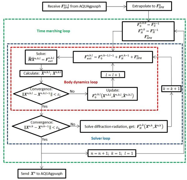
The dynamics solver is integrated in the diffraction–radiation solver package used to calculate the action of wave loads on the floating body. Then, since the body dynamics solver is implicit and non-linear, it requires iterating in order to achieve convergence within each time step. As shown in Figure 1, there are two iterative loops within each time step. Where is the body position vector, is the body velocity vector, is the body acceleration vector, are the external forces other than hydrodynamic loads, are hydrodynamic loads, and is the internal tanks vector of forces and moments computed by the SPH solver. With regards to superscripts, “n” represent the current time step, “k” represents the k-th iteration of the solver loop, and “l” represents the l-th iteration of the body dynamics loop.
On the one hand, the outer loop iterates over the hydrodynamics solver obtained from the diffraction–radiation problem. On the other hand, the inner loop iterates over the body dynamics solver updating any other loads acting on the body dynamics.
Looking at Figure 1, it can be observed that the diffraction–radiation problem and the body dynamics are solved within the time marching loop, and hence the same time step is used for both solvers. Regarding the SPH solver, it requires a smaller time step, and the exchange of data with the body dynamic solver will be carried out once per time step.
Regarding the body dynamics equations, the Bossak-Newmark’s average acceleration method was implemented (Wood et al., 2005). The iterative procedure of the inner loop requires a relaxation schemes to ensure convergence. Aitkens method was used to relax body accelerations with the aim of accelerating the convergence of the iterative algorithm (Irons and Tuck, 1969). Let be the standard difference operator, and the iteration counter, the resulting algorithm of the body dynamics loop can be written as:
- (1) Set iteration .
- (2) Compute forces and moments acting on body: .
- (3) Solve: .
- (4) Compute relaxation factor: .
- (5) Relaxation step: .
- (6) Check convergence. If not reached advance iteration and go to (b).
4. Coupling scheme
4.1. Communication issues
The seakeeping and internal flow solvers used in this work are independently developed, compiled, and distributed software. Therefore, the development and implementation of a communication strategy between them is a key point of the work.
The general idea of the designed coupling scheme is trivial: body movements calculated by the seakeeping solver are sent to the internal flow solver where forces and moments are evaluated and sent back to the seakeeping solver.
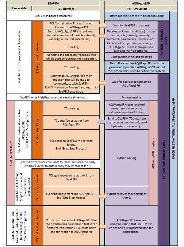
For the exchange of data, the seakeeping solver has a TCL interface, allowing to execute TCL scripts that can access different internal data structures of the solver during the calculation process. For its part, the internal flow solver includes a Python-based interface, developed to interchange data with external sources.
In order to implement the communication scheme, a TCL script [5] was built, which is responsible for the communication between the two programs. This script is interpreted and executed by the seakeeping solver and communicates with different instances of the internal flow solver. Figure 2 explains the communication scheme used.
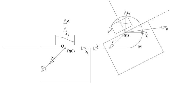
The exchange of data is carried out with respect to an instantaneous reference system. Tables 1 and 2 show the data sent from the seakeeping solver to the internal flow solver and vice versa.
The instantaneous reference system at time=t, ( ) , is defined such that ( ) coincides with the global reference system , ( ) describes the trajectory of the point of the rigid body located initially at the origin of the global system, and axes are parallel to the global axes. To further understand the reference systems used, a simple rigid body movement is presented at Figure 3 showing the displacements and rotations.
| Elapsed simulation time at each time-step | |
| Coordinates of the body reference point referred to the global system | |
| Rotation Angles referred to the global system of the body | |
| Linear velocities of the body reference point referred to the global system | |
| Angular velocities of the body referred to the global system |
| Internal flow forces referred to the global system | |
| Internal flow moments referred to the global system |
4.2. Coupling algorithm
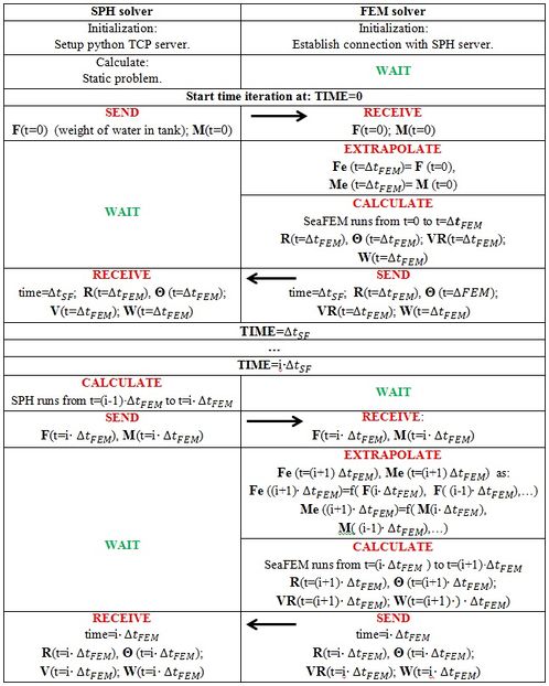
The key point in this work is how the coupling between the two solvers is carried out. As aforementioned, both solvers run in the time domain. Therefore, the coupling is based on the exchange of data in Tables 1 and 2 at some specific time steps while both are running. The time step required by the SPH solver ( ) stability criteria is usually in the order of 10 to 1000 times smaller than the time step used by the seakeeping solver ( ), depending on the case under study, the grid resolution and number of particles. Then, an explicit staggered approach was selected as the most adequate to couple both solvers. This scheme is summarized next:
- 1. Loads calculated by the internal flow solver at are sent to the seakeeping solver.
- 2. The seakeeping solver extrapolates loads from the internal flow solver at using a five points Lagrange polynomial.
- 3. The seakeeping solver calculates movements at .
- 4. The seakeeping solver sends movements to the internal flow solver at .
- 5. The internal flow solver runs from to interpolating the body movements sent by the seakeeping solver from to .
Figure 4 provides the details of the coupling algorithm implemented between the seakeeping and internal flow solvers, where and are the forces and moments sent to the seakeeping solver respectively, and are the extrapolated forces and moments respectively, and are the linear and angular movement of the internal tank respectively, and and are the linear and angular velocities of the internal tank respectively. Figure 1 also shows how external forces and moments are introduced in the body dynamics solver at the beginning of the time step, and how the movements are sent to the SPH solver once the dynamics solver has converged.
5. Validation
5.1. Barge with water in tanks.
5.1.1. Case description
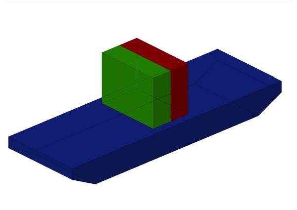
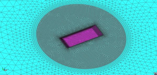
In order to validate the present coupled internal flow-seakeeping solver, experimental results obtained by Molin et al. (2002) were used to compare with. The experiments consist on the study of the seakeeping response of a barge-like ship, where a tank is extending over a relatively large part of the model. There are two tanks next to each other at the mid-ship whose transverse dimension is close to the model breadth. Figure 5 shows the barge layout with the tanks and Figure 6 shows the unstructured mesh used in the seakeeping solver for the present case study. The mesh size in the floating line is 2.5 cm, and a total of 236,144 tetrahedral elements were used.
5.1.1 Case 1: same water level in tanks.
The first case study to analyze is that where the water level is 19cm in both tanks. To achieve the target draft of 10.8cm, additional mass of 40kg was added on the deck of the barge. Table 3 provides the particulars of the barge including the additional mass. Only roll values were provided in Molin et al. (2002). Numerical simulations were carried out with free sway, heave and roll in order to better approximate the experiments. Since both tanks are filled with the same water level, and movements are occurring in the OYZ plane, only one tank was simulated and the second was assumed to behave equally.
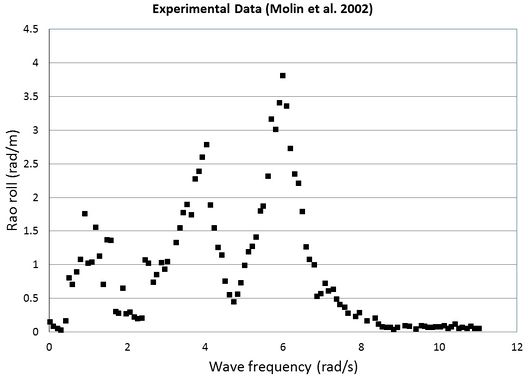
Figure 7 represents the experimental results for the case study where both tanks are filled with the same water level (19 cm). The roll rao in the experiments was obtained via spectral analysis from irregular motion tests. The wave spectrum used was a JONSWAP with particulars provided in Table 4.
| Length | 3 m |
| Breath | 1 m |
| Target draft | 0.108 m |
| Displacement | 275kg |
| XG | 0 m |
| YG | 0 m |
| ZG | 0.14 m |
| Radii of gyration respect to G: Rxx | 0.3704 m |
| Peak enhancement factor | 2 |
| Significant wave height | 6.6 cm |
| Peak period | 1.6 s |
5.1.2.1 Monochromatic wave test
First, a calibration of the roll damping to account for viscous effects is carried out. A monochromatic test with wave amplitude of 2 cm and wave frequency , which is where the first resonance appears. The test was carried out with 105 particles and it was found that 11% of the critical roll damping was necessary to reproduce the RAO value of the experiments, larger than the 8% of the critical damping in Ludvigsen et al. (2013).
Secondly, several tests were carried out to check the effect of increasing the number of particles in the SPH solver. We select a wave frequency , which corresponds to the second resonance frequency in Figure 7. All cases were simulated including a damping factor of , where is the roll inertia of the system barge plus weights, and is the roll hydrostatic restoring coefficient.
Table 5 provides the roll amplitude obtained for each case. The amplification factor converges, slowly, to a value about 2.7.
| Number of particles | RAO Roll [rad/m] |
| 10,000 | 2.29 |
| 35,000 | 2.45 |
| 100,000 | 2.55 |
| 250,000 | 2.60 |
| 500,000 | 2.64 |
5.1.2.2 Irregular wave test
Next a RAOs analysis test is carried out. The wave conditions used in the numerical simulation correspond to a JONSWAP spectrum with similar characteristics of that used in the experiments (see Table 4).
The wave amplitude distribution used to mimic the irregular wave conditions of the experiments is provided in the Appendix A. The discretization of the wave spectrum was done using 51 frequencies from 2.5 to rad/s (this is about the frequency resolution used for the experiments). Also a roll damping was used.
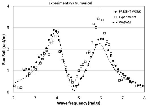
Figure 8 compares the results obtained in the present work using one hundred thousand particles against those from experiments and calculated by WADAM in Ludvigsen et al. (2013) using a potential flow approach to account for the fluid dynamics within the tank. It can be observed that while WADAM provides a smooth curve of results, experiments and the present work show a bit of noise in the obtained curve. We believe that this is because the SPH approach for the fluid flow in the tank is nonlinear, which contributes to energy transfer among frequencies.
For frequencies around , experiments show larger values than those obtained in the computational analyses. On the other hand, results obtained in this work are a bit larger than those obtained by WADAM, and they both compare quite well with the experiment for frequencies away from .
5.1.2.3 Computational time
Table 6 provides some data regarding the computational effort needed for the present approach. The computational time corresponds to those cases presented at Section 5.1.1. It is observed that the calculation of the fluid flow within the tank using the SPH with more than 3.5·104 particles is much more expensive than calculating the seakeeping behavior. Furthermore, if the number of particles is bumped up to 5·105 then this solver takes more than 98% of the calculation time.
| Number
of particles |
(ms) | (ms) | Simulation
time (s) |
Computational
time (s) |
SPH
(%) |
FEM
(%) |
| 10,000 | 1.17 10-3 | 10-2 | 30 | 1938 | 33.5 | 66.5 |
| 35,000 | 7.7 10-4 | 10-2 | 30 | 4109 | 68.4 | 31.6 |
| 100,000 | 5.4 10-4 | 10-2 | 30 | 13110 | 88.5 | 11.5 |
| 250,000 | 4.0 10-4 | 10-2 | 30 | 41577 | 95.5 | 4.5 |
| 500,000 | 3.2 10-4 | 10-2 | 30 | 98616 | 98.2 | 1.8 |
For all cases presented in Table 6, the artificial speed of sound for the SPH was set to 10m/s, and the maximum particle velocity during the simulation was in the order of 0.6m/s, which keeps the Mach number under 0.06.
5.1.2 Case 2: different water level in tanks.
The second case study to analyze is for the case where the water level in one tank is 19cm and in the other 39cm. No additional mass is necessary to achieve the target draft like in the previous case study. The wave amplitude distribution used to mimic the irregular wave conditions of the experiments is provided in Appendix A. The discretization of the wave spectrum was done using one 101 frequencies ranging from 2.5 to 8 rad/s (frequency resolution was increased respect to the experiments to be able to catch the middle resonance peak shown in the experiments). Also a roll damping was used. The main particulars of the barge for this case study are given in Table 7.
| Target draft | 0.108 m |
| Displacement | 275kg |
| XG | 0 m |
| YG | 0 m |
| ZG | 0.132 m |
| Radii of gyration respect to G: Rxx | 0.414 m |
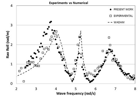
Figure 9 compares the results obtained in the present work against those from experiments and calculated by WADAM in Ludvigsen et al. (2013). 105 Particles were used in the 19cm filling tank, and two hundred thousand particles in the 39cm filling tank. In this case study, three resonance peaks appear. For frequencies around the largest deviation from numerical to experimental results is found. But, for frequencies that are around no apparent deviation of the peaks’ frequency is observed and the numerical results around the sharp peak achieve a very similar value to the experimental results. Finally, for frequencies around , no deviation in frequency is observed, but numerical results are below the predicted peak value.
The following videos show a side view and a frontal view of the computational analysis done in this case.
| Video 1. Side view of the validation case. |
| Video 2. Frontal view of the validation case. |
5.1.3 Case Datafiles
The folowing spreadsheets contain the experimental and numerical results for the current validation case (same water level and different water level).
Moulin_Jonswap_spectrum_data.xlsx
Moulin_SameLevel_experimental_data.xlsx
Moulin_SameLevel_Monochromatic_Convergence_tests.xlsx
Moulin_SameLevel_Rao_Comparison.xlsx
Moulin_DifferentLevel_Rao_Comparison.xlsx
5.2 Antiroll tank analysis
Bai and Rhee (1987) provided experimental RAOs, obtained in a model basin, for a supply vessel equipped with an anti-roll tank (ART). Later on, Kim et. al (2002) and Kim et al. (2007) carried out numerical simulations of a modified S175 hull in order to compare the results with the experimental data provided in Bai and Rhee (1987). The modified S175 hull used by Kim et. al (2007) was an approximation to the supply vessel used by Bai and Rhee and, despite of it, results obtained by Kim et. al (2007) numerically showed the same trends than the experimental ones.
In this work, we followed Kim et. al (2007) approach using a modified S175 hull to approximate the supply hull used by Bai and Rhee (1987). We used the same aspect ratios of beam to length, and draft to length used by Kim et al. (2007), for the modified S175 hull and the ART. However, no information regarding the exact geometry was found, neither for the position of the gravity center nor for inertias. Therefore, we had to estimate some parameters as well as the hull form.
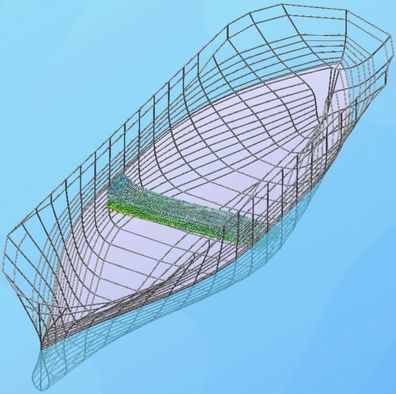
We started with the S175 hull form provided by the ITTC web site. Then, we proceeded to scale the ship to fulfill the aspect ratios provided by Kim et. al (2007). The resulting geometry is provided in [6]. The longitudinal positions of the gravity center and ART was estimated as the longitudinal position of the buoyancy center. Transverse positions was set to Y=0 and the vertical position of the gravity center and roll radii of gyration were estimated to approximate roll RAOS results without ART provided by Kim et. al. (2007). Tables 8 and 9 provide the main particulars of the hull form and ART used in this work. Figure 10 shows the modified S175 hull with the ART in place.
| Length between perpendiculars ( ) | 47.6 m |
| Breadth | 13.7088 m |
| Draft | 3.9984 m |
| Displacement | 1498.4 T |
| XFP | 23.8 m |
| XAP | -23.8 |
| XG | -0.73 m |
| YG | 0 |
| ZG | -0.25 m |
| Radius of roll gyration Rxx | 6.26 m |
| Length | 2. 8 m |
| Breadth | 13.699 m |
| Draft | 2.4 m |
| Fresh water filling | 50 % |
| XT (mid tank) | -0.73 m |
| YT (mid tank) | 0 m |
| ZT (base tank) | -1.8564 m |
Roll RAOs were obtained for a series of tests with monochromatic waves and were normalized with respect to the maximum wave slope , where is the wave amplitude, and the wave number. Also a damping factor of was used to calibrate the RAO value near resonance.
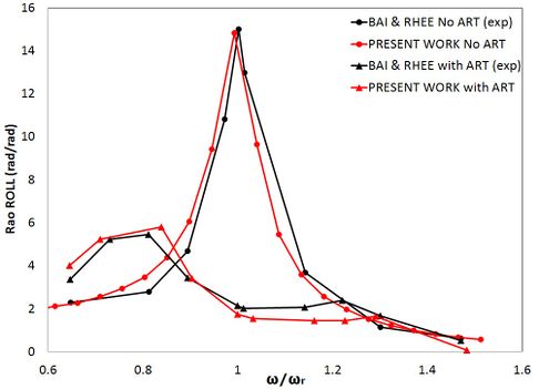
Figure 11 compares the experimental results obtained by Bai and Rhee (1987) with the numerical results obtained in this work where the results are shown with and without ART. 104 Particles were used in the SPH solver for the ART SPH simulation. The modified S175 was calibrated to show a similar behavior to the supply vessel of Bai and Rhee without ART, as can be observed by comparing the RAOs results without ART. When inserting the ART the results tend to be the same to the ones obtained by Bai and Rhee with a very similar reduction of roll movements.
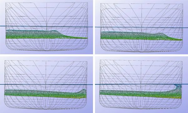
Figure 12 presents snapshot of the modified S175 hull with the ART at the resonance wave frequency for the case when there is no ART. It can be observed that the roll motion is very small, and the fluid flow inside the ART is very nonlinear, exhibiting wave breaking phenomena.
5.2.1 Case Datafiles
The following spreadsheet contains the data relevant to this case including model data, results and graphs.
Art_results.xlsx
5.3 2D vessel including internal flows
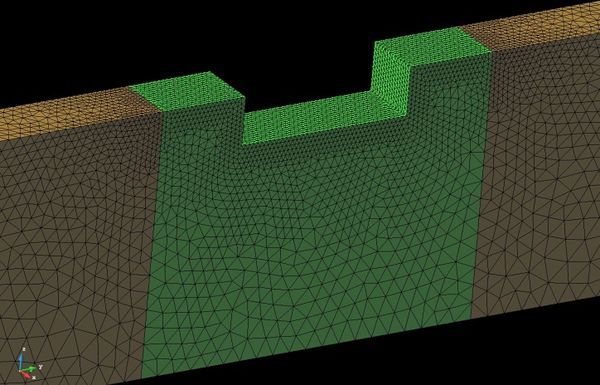
Zhao et al. (2014b) carried out a series of two-dimensional model tests to study the hydrodynamic performance of a floating liquefied natural gas (FLNG) section including internal flow oscillations. The reference FLNG section was ballasted with fresh water and equivalent solid weights respectively, to clarify the coupling effects. RAOs of both motion responses and internal sloshing flows were calculated based on measured data. Particulars of the vessel section, internal tank, and complete model are provided in Tables 10-12, and Figure 13 shows the 3D FEM mesh model used for the simulation.
| Tank | Full scale | model scale |
| Length (m) | 40 | 0.8 |
| Breadth (m) | 10 | 0.2 |
| Water level (m) | 18 | 0.36 |
| Mass (kg) | 7.2 E+06 | 57.6 |
| ZG (m) | -4.72 | -0.0944 |
| Inertia respect to tank CG Ixx (kg m2) | 1.15 E+09 | 3.69 |
| Radius of roll gyration Rxx (m) | 12.7 | 0.25 |
| Section | Full scale | Model scale |
| Length (m) | 50 | 1 |
| Breadth (m) | 17.5 | 0.35 |
| Mass (kg) | 4.805 E+06 | 38 |
| ZG (m) | -1.0473 | -0.021 |
| Inertia respect to section CG Ixx (kg m2) | 1.027 E+09 | 3.287 |
| Radius of roll gyration Rxx (m) | 14.621 | 0.2924 |
| Complete model | Full scale | model scale |
| Draft (m) | 13.72 | 0.2744 |
| Mass (kg) | 1.20 E+07 | 96.04 |
| ZG (m) | -3.25 | -0.065 |
| Inertia respect to complete model CG Ixx (kg m2) | 2.22 E+09 | 7.1054 |
| Radius of roll gyration Rxx (m) | 13.6 | 0.272 |
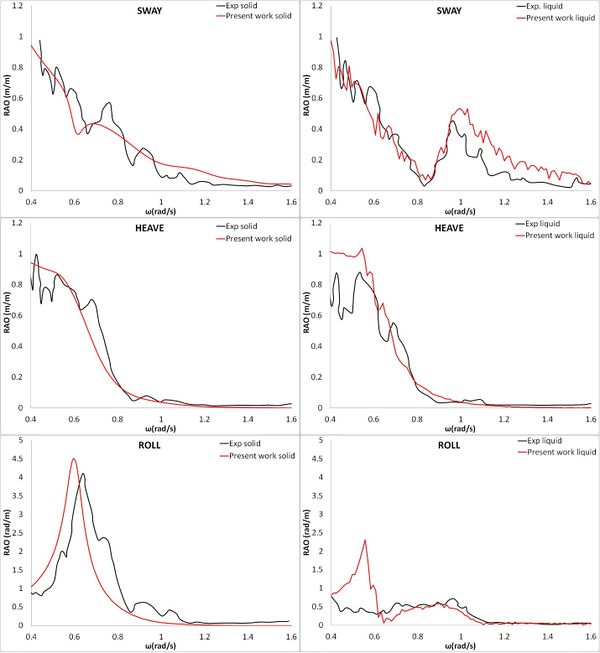
A white noise spectrum, with an energy density approximated to the one used in the experiments, was used to carry out the simulations. It consists of 51 frequencies equally spaced between and , with a wave amplitude of . First of all, uncoupled simulations with the equivalent solid weight were carried out to calibrate damping coefficients. Comparing with the solid weight experimental results (see Figure 14, left), damping coefficients were estimated as for heave, and for roll. Secondly, coupled simulations were carried out using around 104 particles within the tank. Raos comparisons are provided in Figure 14 (right).
Overall, the results obtained in this work fit well the experimental results provided by Zhao et al. (2014b). Some differences appear regarding the resonance frequency in roll, which might be due to the experimental setup to enforce the 2D condition, which is not fully simulated in the computational model. Besides, the numerical results for the coupled problem shows a peak value in frequencies around the resonance frequency for the uncoupled problem. Although this effect is not present in the experimental results, it was observed in the previous case study with the antiroll tank. So the appearance of this peak is not surprising and the appearance or not is questionable.
5.3.1 Case Datafiles
The following spreadsheet contains model data, results from the different cases and the graphs used for the current document.
Zhao_results.xlsx
Conclusions
In this work, a SPH flow solver and a FEM seakeeping solver were coupled to perform simulations of seakeeping dynamics and internal flows in tanks simultaneously. Both solvers run independently in the time–domain, hence a coupling algorithm, including a communication strategy, was developed.
The SPH-FEM coupling showed to be effective for solving seakeeping dynamics coupled with internal flows including sloshing. It was validated for several cases against available experimental data, providing good agreement. For the specific case study of the modified S175 hull with antiroll tank, where sloshing effects were observed, good agreement was found, demonstrating the capability of incorporating highly non-linear phenomena. As a result, the proposed coupling strategy has the capability of performing complex seakeeping analysis coupled with highly non-linear internal flows in reasonable computational times.
This coupled solver will be applied in a future work to solve realistic problems including LNG transportation analysis and complex sloshing phenomena under different sea conditions.
Acknowledgments
The research leading to these results has received funding from the Spanish Ministry for Economy and Competitiveness under Grants TRA2013-41096-P (OPTIMIZACIÓN DEL TRANSPORTE DE GAS LICUADO EN BUQUES LNG MEDIANTE ESTUDIOS SOBRE INTERACCIÓN FLUIDO-ESTRUCTURA) and ENE2014-59194-C2-2-R (X-SHEAKS: CAMPAÑA EXPERIMENTAL Y VALIDACIÓN). The first author gratefully acknowledges the support of NVIDIA Corporation with the donation of the Tesla K20 GPU used for this research.
References
Antuono M., Colagrossi A. and Marrone S., “Numerical diffusive terms in weakly-compressible SPH schemes”, Comput. Phys. Commun. 183, 2012, 570–2580.
Antuono M., Marrone S., Colagrossi A. and Bouscasse B., “Energy balance in the δ-SPH scheme”, Comput. Methods Appl. Mech. Eng. 289, 2015, 209–226.
Bai K.J. and Rhee K.P., “Roll-Damping Tank Test”. Project report, 1987, Seoul National University.
Bouscasse B., Colagrossi A., Souto-Iglesias A. and Cercos-Pita J.L., “Mechanical energy dissipation induced by sloshing and wave breaking in a fully coupled angular motion system”. I. Theoretical formulation and numerical investigation, Phys. Fluids (1994–present) 26, 2014a, 3.
Bouscasse B., Colagrossi A., Souto-Iglesias A. and Cercos-Pita J.L., “Mechanical energy dissipation induced by sloshing and wave breaking in a fully coupled angular motion system”. II. Experimental investigation, Phys. Fluids (1994–present) 26, 2014b, 3.
Bulian G., Souto-Iglesias A., Delorme L. and Botia-Vera E., “SPH simulation of a tuned liquid damper with angular motion”, J. Hydraul. Res. 48 (Extra Issue), 2010, 28–39.
Cai X., Langtangen H.P., Nielsen B.F. and Tveito A., “A finite element method for fully nonlinear water waves”, J. Comput. Phys. 143, 1998, 544–568.
Campbell P.M., Some New Algorithms for Boundary Value Problems in Smooth Particle Hydrodynamics, 1989, Defense Nuclear Agency; USA.
Cercos-Pita J.L., “Aquagpusph, a new free 3D SPH solver accelerated with OpenCL”, Comput. Phys. Commun. 192 (0), 2015, 295–312.
Cercós-Pita, J. L., Bulian, G., Pérez-Rojas, L., and Francescutto, A. (2016). “Coupled simulation of nonlinear ship motions and a free surface tank”. Ocean Engineering, 120:281–288.
Cercós-Pita, J. L. and Bulian, G. (2016b). “Cosimulation of ship motions and sloshing in tanks”. (Under review)
Colagrossi A., Antuono M. and Le Touzé D., “Theoretical considerations on the free-surface role in the smoothed-particle-hydrodynamics model”, Phys. Rev. E (Stat. Nonlinear Soft MatterPhys.) 79 (5),2009, 056701.
Colagrossi A., Antuono M., Souto-Iglesias A. and Le Touzé D., “Theoretical analysis and numerical verification of the consistency of viscous smoothed-particle hydrodynamics formulations in simulating freesurface flows”, Phys. Rev. E 84, 2011, 26705.
Colagrossi A., Souto-Iglesias A., Antuono M. and Marrone S., “Smoothed-particle-hydrodynamics modeling of dissipation mechanisms in gravity waves”, Phys. Rev. E 87, 2013, 023302.
Colagrossi A., Bouscasse B. and Marrone S., “Energy-decomposition analysis for viscous free-surface flows”, Phys. Rev. E 92, 2015, 053003.
Crespo A., Dominguez J., Barreiro A., Gómez-Gesteira M. and Rogers B., “GPUs, a new tool of acceleration in CFD: Efficiency and reliability on smoothed particle hydrodynamics methods”, PLoS ONE 6, 2011, 6.
De Leffe M., Le Touzé D. and Alessandrini B., “Normal flux method at the boundary for SPH”, In: Proceedings of the 4th ERCOFTAC SPHERIC Workshop SPH Appl. 2009, 149–156.
Dominguez J.M., Crespo A.J.C., Valdez-Balderas D., Rogers B.D. and Gómez-Gesteira M., “New multi-GPU implementation for smoothed particle hydrodynamics on heterogeneous clusters”, Comput. Phys. Commun. 184, 2013, 1848–1860.
Ferrand M., Laurence D.R., Rogers B.D., Violeau D. and Kassiotis C., “Unified semi-analytical wall boundary conditions for inviscid, laminar or turbulent flows in the meshless SPH method” Int. J. Numer. Methods Fluids 71, 2013, 446–472.
Herault A., Bilotta G. and Dalrymple R.A., “SPH on GPU with CUDA”, J. Hydraul. Res. 48 (Extra Issue), 2010, 74–79.
Irons B.M. and Tuck R.C., “A version of the Aitken accelerator for computer iteration”, Int. J. Numer. Methods Eng. 1, 1969, 275–277.
Li Y., Zhu R., Miao R. and Fan, J G., “Simulation of tank sloshing based on OpenFOAM and coupling with ship motions in time domain”, J. Hydrodyn., Ser. B 24 (3), 2012, 450–457.
Kim Y., “A numerical study on sloshing flows coupled with ship motion—the anti-rolling tank problem”, J. Ship Res. 46 (1), 2002, 52–62.
Kim Y., Nam B.W., Kim D.W. and Kim Y.S., “Study on coupling effects of ship motion and sloshing”, Ocean Eng. 34, 2007, 2176–2187.
Kulasegaram S., Bonet J., Lewis W.R. and Profit M., “A variational formulation based contact algorithm for rigid boundaries in two-dimensional SPH applications”, Comput. Mech. 33 (4), 2003, 316–325.
Ludvigsen, A., Pan, Z.Y., Gou, P., Vada, T., 2013. “Adapting a linear potential theory solver for the outer hull to account for fluid dynamics in tanks”. In: Proceedings of the ASME 2013 32nd International Conference on Ocean, Offshore and Arctic Engineering OMAE2013 June 9–14, Nantes, France.
Ma Q.W. and Yan S., “QALE-FEM for numerical modelling of non-linear interaction between 3D moored floating bodies and steep waves”, Int. J. Numer. Methods Eng. 78 (6), 2009, 713–756.
Macià F., Antuono M., González L.M. and Colagrossi A., “Theoretical analysis of the no-slip boundary condition enforcement in SPH methods”, Progress. Theor. Phys. 125 (6), 2011, 1091–1121.
Macià F., González L.M., Cercos-Pita J.L. and Souto-Iglesias A., “A boundary integral SPH formulation”. Consistency and applications to ISPH and WCSPH, Progress. Theor. Phys. 128 (3), 2012, 439–462.
Molin, B., Remy, F., Rigaud, S., de Jouette Ch., 2002. “LNG-FPSO’s: frequency domain coupled analysis of support and liquid cargo motions”. In: Proceedings of INAM Conference, Rethymnon, Greece.
Monaghan J.J., “Simulating free surface flows with SPH”, J. Comput. Phys. 110, 1994, 399–406.
Neves M.A.S., Merino J.A. and Rodríguez C.A., “A nonlinear model of parametric rolling stabilization by anti-roll tanks”, Ocean Eng. 36 (14), 2009, 1048–1059.
Nishiura D., Furuichi M. and Sakaguchi H., “Computational performance of a smoothed particle hydrodynamics simulation for shared-memory parallel computing”, Comput. Phys. Commun. 194 (0), 2015, 18–32.
Serván-Camas B. and García-Espinosa J., “Accelerated 3D multi-body seakeeping simulations using unstructured finite elements”, J. Comput. Phys. 252, 2013, 382–403.
Souto-Iglesias A., Delorme L., Rojas L.P. and Abril S., “Liquid moment amplitude assessment in sloshing type problems with SPH”, Ocean Eng. 33, 2006, 11–12.
Watai R.A., Dinoi P., Ruggeri F., Souto-Iglesias A. and Simos A.N., “Rankine time–domain method with application to side-by-side gap flow modeling”, Appl. Ocean Res. 50 (0), 2015, 69–90.
Wood W.L., Bossak M. and Zienkiewicz O.C., “An alpha modification of Newmark's method”, Int. J. Numer. Methods Eng. 5 (10), 2005, 1562–1566.
Yan, S., Ma, Q.W., Cheng, X., 2011. “Fully nonlinear simulation of two floating structures in close proximity subjected to oblique waves”. In: Proceedings of the 21st International Offshore and Polar Engineering Conference (ISOPE). The International Society of Offshore and Polar Engineers (ISOPE).
Zhao W.H., Yang J., Hu Z.Q. and Wei Y.F., “Recent developments on the hydrodynamics of floating liquid natural gas (FNLG)”, Ocean Eng. 38, 2011, 1555–1567.
Zhao W., Yang J., Hu Z. and Tao L., “Coupled analysis of nonlinear sloshing and ship motions”, Appl. Ocean Res. 47 (0), 2014a, 85–97.
Zhao W., Yang J., Hu Z., Xiao L. and Tao L., “Hydrodynamics of a 2D vessel including internal sloshing flows”, Ocean Eng. 84, 2014b, 45–53.
Web references
[1] CompassIS (last accessed: January 20th 2016): http://www.compassis.com/seafem.
[2] Centre Internacional de Metodes Numerics en Enginyeria (last accessed: January 20th 2016): http://www.cimne.upc.edu.
[3] CEHINAV Res. Gr., DMFPA, ETSIN, Technical University of Madrid (last accessed: January 20th 2016). http://canal.etsin.upm.es/.
[4] AQUAgpusph (last accessed: January 20th 2016): http://canal.etsin.upm.es/aquagpusph/.
[5] Tcl (Tool Command Language) [on-line] (last accessed: January 20th 2016): http://www.tcl.tk
[6] (last accessed: January 20th 2016): (http://canal.etsin.upm.es/papers/servanetal2016/)
Document information
Published on 01/01/2016
DOI: 10.1016/j.oceaneng.2016.07.003
Licence: CC BY-NC-SA license
Share this document
claim authorship
Are you one of the authors of this document?
