1. Introduction
The study of shear states entails a higher degree of difficulty than any of the existing methodologies, with a greater variety of test methods proposed in recent decades than for any other mechanical testing of composite materials [1-3]. One of the reasons for so many attempts is the difficulty of obtaining a reasonably pure and uniform shear stress state in the test specimen, which is essential if shear properties are to be measured. Another problem is that some methods adequately determine the shear modulus, but not the shear strength. Therefore, it is of interest for the design of structures to have a methodology that meets these conditions. The tension-compression test with cruciform specimens (TC test) is proposed as an alternative to the existing methodologies for determining shear properties because it satisfies the main needs raised. This allows a uniform stress state to be concentrated in the center of the specimen, from which pure shear conditions can be obtained. In addition, it is possible to observe the linear and non-linear evolution of the stress-strain curve up to high levels of strain, higher than those of most shear tests. As the failure is triggered in the biaxially loaded region, it is possible to calculate both the stiffness from the initial linear stage and the shear strength.
The UNE 0074:2023 Specification entitled “Plastic materials. Shear test method by means of tension-compression on cruciform specimen" [4] has been carried out by the Spanish Association for Standardization UNE, within the technical committee 53 "Plásticos y Caucho" (CNT 53) in the working group 8 (GT8). The University of Castilla-La Mancha (UCLM), the AIMPLAS-Plastic Technological Institute, the Eduardo Torroja Institute for Construction Sciences and the company Siemens-Gamesa have participated in its writing. The document describes the method to determine the shear mechanical response of plastics with and without reinforcement. The Specification is based on the research carried out by the research group of Continuum Mechanics, Structures and Materials (COMES) of the UCLM in the COMMUL and BISHEAR projects developed within the framework of the national programs of R&D oriented towards the challenges facing society 2016 and the "Proof of Concept" projects 2021. The main features of the pre-standard are described below, referring the reader to review the entire document for a greater detail [4].
2. UNE 0074:2023 Specification
The UNE 0074:2023 Specification specifies a test method in which the central region of a cruciform specimen is subjected to a biaxial state in which tension is applied on the arms of the specimen in one direction and compression of equal modulus in the perpendicular direction. The methodology is applicable to symmetric and balanced polymer based laminates with the fibres oriented at ±45° with respect to the two directions of the arms in which the load is applied. The method is suitable for determining shear properties in the linear and non-linear stress-strain ranges, even at large shear strains (greater than 5%).
2.1. General configuration
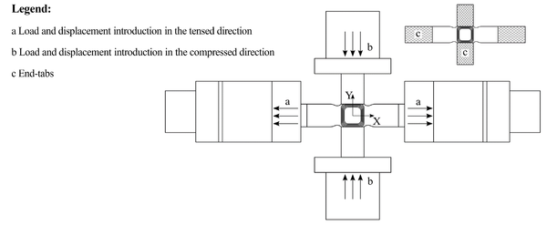
A schematic of the kinematics and boundary conditions of the test is presented in Fig. 1, in which X and Y are the tensed and compressed loading directions respectively. The specimen is placed in the testing machine, taking special care to align the center of the sample with the center of the machine. The tensed arms are placed inside the gripper jaws, which must apply a uniform and reproducible pressure. The arms can be subjected to compression by means of compression plates or equivalent devices. During the test, the machine must be able to control either the loads applied to the X- and Y-arms of the specimen (FX and FY), or the X- and Y-displacements applied by the actuators (uX and uY), or the X- and Y-strain generated in the central region of the specimen. In case of a force control, the ratio FX/FY = 1/–1 must be kept constant during the test. In case of carrying out a control by displacement, during the test the ratio between the displacements uX and uY must remain invariable, in such a way that uX/uY = 1/–1. In the case of carrying out a strain control in the gauge region, the ratio εXX/εYY = 1/–1 must be kept constant during the test. A test speed of 20 N/s is recommended if a load control is chosen, 1 mm/min is preferred if a displacement control is performed, or it should be ensured that the total test time does not exceed 10 min.
2.2. Recommended cruciform specimen
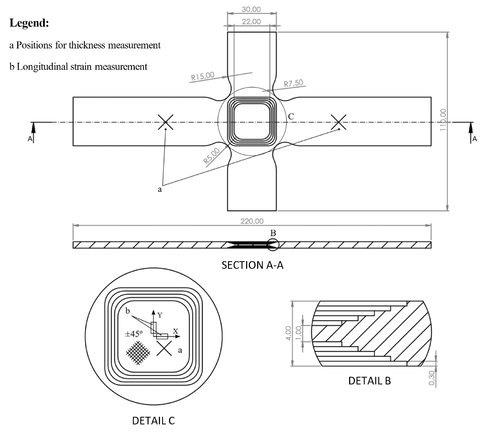
Fig. 2 shows the geometry of the recommended cruciform specimen and the fibre orientations. The test specimen should have an arm width of 30 mm and a gauge region of dimensions 22 x 22 mm2, ensuring the flatness of the sample. Unless otherwise specified, the recommended thicknesses for the gauge region and the arms of the specimen are 1 mm and 4 mm respectively. To generate the tapered central region, machining by numerical control is recommended. However, other manufacturing methodologies can be used that generate the geometry from the beginning with the required shape, such as the resin infusion process, fused deposition modeling or layer stacking that takes into account the ply drop of the central zone. The use of end-tabs on the arms is recommended as shown in Fig. 1. Likewise, an auxiliary tool can be used to avoid the arms instability while allowing the measurement of strains in the central region [5]. It should be noted that an alternative geometry of the cruciform specimen could be used. For example, the thickness reduction in the gauge region could be ramped or circular and the zone of intersection of the arms could be filleted with a single fillet radius or with an elliptical shape. In any case, the gauge region thickness must be selected to avoid the out-of-plane deflection, being recommended that the arms of the specimen have a thickness at least 4 times greater than that of the central zone. The conversion factor used for the recommended geometry, which relates the normal stresses in the gauge region with the loads applied to the arms of the cruciform specimen, is the same in both load directions and takes the value of f = 3.7 (Eq. 1 and Eq. 2) [4]. The use of an alternative geometry for the cruciform specimen or dimensional changes to suit the setup of the equipment may invalidate the stated conversion factor value.
2.3. Measurements
The test method requires the strain acquisition in the central region of the specimen at angles of 0° and 90° with respect to the X-direction (Fig. 2). Strain gauges and/or optical measurement systems are recommended to be utilised, also measuring the strain in the compressed direction of the rear tapered region to take into account possible deviations which would indicate out-of-plane displacements. The strains in the gauge region at the loading directions, as well as the loads applied to the arms of the specimen and the displacements of the actuators must be recorded throughout the test at constant time intervals.
The thickness of the specimen must be measured in the central region and in the arms for subsequent calculations (Fig. 2). One measurement of the thickness in the central zone is considered enough. Meanwhile in the tensed arms the thickness must be taken in 2 positions from the area that is not covered by the end-tabs to determine its average value.
2.4. Procedure
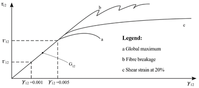
Specimens should be tested until at least five non-rejectable results are obtained. The test ends when one of the following three failure modes is fulfilled (Fig. 3): i) the shear stress vs. shear strain diagram presents a global maximum, which corresponds to the shear strength; ii) failure occurs between fibers, considering that the shear strength is the stress acquired at the moment when the first break between fibers occurs; iii) if no failure occurs, when a maximum strain of 20% is reached. The failure mode must be verified and recorded.
Knowing the dimensions of the arms cross sections, called AX and AY respectively, the normal stress components in the central area of the specimen in the two load directions, and can be calculated from Eq. 1 and Eq. 2.
|
|
(1) | |
|
|
(2) |
Then, in a reference system rotated 45º to the X-Y axes, a pure shear state would be produced in which the maximum value of the shear stress is given by Eq. 3, with the corresponding engineering strain calculated with Eq. 4.
|
|
(3) | |
|
|
(4) |
3. Results
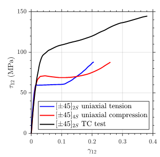
The procedure recommended by the UNE 0074:2023 specification has been satisfactorily applied for determining the shear stress-strain evolution of a M21E epoxy matrix reinforced with 34% by weight of IMA-12-K unidirectional carbon fiber, achieving shear strain levels close to 40% using a anti-buckling device (Fig. 4). These results have been recently published in reference [6] and they are shown in the communication titled “Análisis numérico-experimental del estado tensión-deformación de cortadura pura obtenido mediante el ensayo biaxial tracción-compresión” submitted to MATCOMP23. The comparison of the pure shear stress-strain evolution in the TC test and that obtained from the ASTM D3518 standard [7], allowed us to observe the improvement of the results with respect to this already existing methodology. ASTM D3518 instructs on how to proceed to obtain the in-plane shear modulus by applying a uniaxial tensile load to a ±45º symmetrical angle-ply laminate. Adequate values of the shear modulus are obtained with the uniaxial tests, but the response at large strains is clearly affected by the combination of normal and shear stresses in the principal directions of the material. This also occurs in the case of carrying out the test by applying a uniaxial compression load on symmetrical ±45º angle-ply laminates.
4. Conclusions
The test methodology recommended in Specification UNE 0074:2023 for determining the pure shear properties of a fibre reinforced polymer in principal material directions is presented. The procedure is based on the biaxial tension-compression test with a cruciform specimen on symmetrical angle-ply ±45º laminates, which is proposed as an alternative that permits to observe higher shear strains than the existing methodologies.
Acknowledgements
The development of the UNE 0074:2023 Specification is part of the project PDC2021-121154-I00, funded by MCIN/AEI/10.13039/501100011033 and by the European Union “NextGenerationEU/PRTR”. In addition, the Ministry of Economy and Competitiveness of Spain and the European Regional Development Fund should be acknowledged for the grant DPI2016-77715-R.
References
| [1] | ASTM D3518/D3518M-18, 2018. Standard Test Method for In-Plane Shear Response of Polymer Matrix Composite Materials by Tensile Test of a ±45◦ Laminate. Standard. American Society for Testing and Materials. | |
| [2] | ASTM D5379/D5379M-19e1, “Standard Test Method for Shear Properties of Composite Materials by the V-Notched Beam Method”, American Society for Testing and Materials, 2019. | |
| [3] | ASTM D7078/D7078M-20e1, “Standard Test Method for Shear Properties of Composite Materials by V-Notched Rail Shear Method”, American Society for Testing and Materials, 2020. | |
| [4] | UNE 0074:2023, 2023. Plastic materials. Shear test method by means of tension-compression on cruciform specimen. Specification. Asociación Española de Normalización. | |
| [5] | M.C. Serna Moreno, S. Horta Muñoz, 2022. Dispositivo para evitar pandeo en ensayos biaxiales de probetas cruciformes. Spanish Utility Model 2022/20461. | |
| [6] | S. Horta Muñoz, M.C. Serna Moreno, Tension-compression biaxial test with ±45° symmetric angle-ply laminates for determining the pure shear response in principal material directions of a lamina, Composites Part B: Engineering, 261, 110792, 2023. | |
| [7] | ASTM D3518/D3518M-18. Standard test method for in-plane shear response of polymer matrix composite materials by tensile test of a ±45◦ laminate. American Society for Testing and Materials; 2018. |
Document information
Published on 31/12/69
Accepted on 31/12/69
Submitted on 31/12/69
Volume 08 - COMUNICACIONES MATCOMP21 (2022) Y MATCOMP23 (2023), Issue Núm. 7 - Caracterización - Sostenibilidad y Reciclaje, 1970
DOI: 10.23967/r.matcomp.2025.07.03
Licence: Other


