1 Introduction
Because of the current level world contamination generated by the high consumption of plastics and their inherent long degradation time, there is a high interest in the research of bio-based greener and safer materials for the replacement of traditional non-renewable petroleum-based polymers. This is the case of foams, one of the worldwide form of polymers used in different industry segments such as packaging, automotive, construction or aeronautics. An aerogel is, in fact, a type of very low-density foam (0,0001 - 0,5 g/cm3).
The first aerogel was created by Kistler [1]in 1931 in which water was removed from a gel through a solvent-exchange drying process. As a result, a solid skeleton was obtained. From this point, an endless number of mainly inorganic aerogels including silica, carbon, but also organic have been developed [2,3]. The utilization of natural renewable polysaccharides in the preparation of bio-based aerogels from diverse sources, such as alginate, cellulose, chitosan, lignin, pectin, proteins or starch represents an interesting innovation in the field[4]. Bio-based aerogels are sustainable materials characterized by biodegradability, hydrophilicity and large surface area. They contain a high amount of air in its interior, which imparts very low densities and low thermal conductivities, making them potential candidates for thermal insulation. However, an improvement in certain properties such as mechanical and fire resistance is necessary for its more general application in industry. Therefore, greener high flame resistant aerogels are highly desired [5].
The addition of inorganic filler is a common and logical method for improving mechanical properties in composites. Van Olphen [6,7]prepared pure clay aerogels by freeze-drying and found that clay particles were linked edge-to-face much like a "house of cards" due to the opposite surface and edge charges that exist in clays. It was also suggested that ice crystals grow radially, pushing clay particles aside and promoting parallel platelet alignment [6-8]. Following this idea, the combination of polymers and clay would yield a system in which polymer plays the role of an adhesive, linking the clay platelets and avoiding the collapse of the brittle clay structure. On the other hand, the alignment of clay particles in a particular direction would enhance the mechanical properties, especially in the loading direction.
Polymer/nanoclay systems can be transformed into suitable aerogels if a homogeneous precursor gel of both components is first achieved. Bio-based polymers such as gelatine [9], cellulose [10]or alginate [11] can be easily dissolved in water forming stable gels. Besides, the dispersion of small amount of layered-smectic clays, has been shown to increase thermomechanical properties of organic matrix polymers, since it can accept and exchange hydrated cations and other polar molecules within interlayer position [12, 13]. Such is the case of aluminium hydroxide Al(OH)3 and montmorillonite (MMT).
Very often, a single polymer matrix is not able to fulfill all the requirements of a certain application. In such cases, the combination of different materials represents a powerful solution. In the present case, two different polymers have been joined, forming a layered system in which polyvinyl alcohol and montmorillonite, PVA/MMT, was selected as the substrate. PVA is biodegradable and due to the strong interaction between the negative charges of the polymer and the positive ones of clay, forms a high-performance aerogel foam. Moreover, due to the large number of hydroxyls contained, it can be easily cross-linked following different routes. Initially, crosslinking was thought necessary to avoid re-dissolution of the base aerogel layer during the addition of the second component.
In this work, PVA/MMT composite aerogels were formed by freeze-drying and were cross-linked with borax in an attempt to improve its mechanical properties. Moreover, for enhancing the behaviour under fire, different top layers based on MMT/Alginate or Al(OH)3 /Alginate, were separately added. It should be mentioned that this research combines different aerogels mainly in a two-layered system as the bottom and top layers define the thermal insulation and fire behaviour. Nevertheless, the proposed approach can be similarly extended to a higher number of layers.
2 Experimental Section
2.1 Materials
Poly (vinyl alcohol) (PVA) (Average Mv 31,000 – 50,000, 98-99% hydrolyzed) and sodium borate were obtained from Aldrich Chemistry. Sodium montmorillonite (PGW grade) was supplied by Nanocor Inc., and Sodium Alginate was obtained from Boter SL. All reagents were used as received without further purification.
2.2 Aerogel preparation
2.2.1 Preparation of base PVA/clay Aerogel
PVA solution (10 wt %) was prepared by dissolving 10 g in 100 ml DI water at 90 ºC under stirring for 3 h. To prepared MMT clay suspension (10 wt%), 100 ml of DI water and 10 g of MMT clay were well dispersed by high-speed stirrer. Then both PVA solution and MMT suspension were combined in equal volumes by low-speed stirring until a homogeneous solution was obtained. After that, the PVA/MMT solution was poured into a mold and rapidly frozen in slurry dry ice and ethanol bath. The frozen samples were dried for 72 h in a Testlar Lyoquest lyophilizer. The resulting sample was named P5C5, where P and C refer to Polymer and Clay respectively and the numbers are the percentages of these materials in DI water.
2.2.1.1 Crosslinking of PVA/clay Aerogel
The PVA/MMT sample, previously frozen in a mold, was submerged into a Borax solution (3 wt%) at approx. 7 ºC for 15 min and 30 min. Then, they were frozen again in a dry ice and ethanol bath and freeze-dried following this. These resulting cross-linked samples were named P5C5B15 and P5C5B30. Where B means borax, followed by a number, which refers to the minutes that the aerogel was exposed to the borax solution. Crosslinking with borax was thought necessary to avoid possible dissolution of the base material during the addition of successive layers.
2.2.2 Preparation of One Step layered Aerogel
The MMT-alginate emulsion was created by mixing 2 wt% and 8 wt% of MMT and alginate respectively with DI water. First, the alginate was mixed with DI water while the clay was being dispersed as well in water. After having homogeneous solutions of both systems, they were mixed in order to obtain a roughly uniformed precursor solution, named 8C2A. Where C and A means clay and alginate respectively. The numbers refer to the proportion of each component into the solution. Once this was done, it was poured on top of the previously molded P5C5 frozen solution. Subsequently, the sample was immersed in ethanol and ice bath for its subsequent freeze-drying.
The same procedure was used for P5C5/8Al2A (1s), where Al refers to Al(OH)3 and the number in parenthesis followed by S, means one step/one lyophilization in both aerogels.
2.2.3 Preparation of Two Step layered Aerogel
The two-step method was started from the previously lyophilized P5C5 aerogel. Then 8C2A emulsion was spread evenly over in the aerogel top face. Afterwards, the sample was frozen again and freeze-dried. The aerogel resulting was P5C5/8C2A (2s), where the 2s in parenthesis, means that the composite was lyophilized two times. The same procedure was used for P5C5/8Al2A (2s) aerogel, Al(OH)3 -alginate emulsion was created by mixing 2 wt% and 8 wt% of each component respectively with DI water.
2.3 Characterization
2.3.1 Apparent density
The aerogel apparent densities were calculated by measuring the mass and dimensions using a Cobos balance (Spain, +0.01 mg precision) and a digital calliper.
2.3.2 Morphology
The microstructure of the samples was characterized by Scanning Electron Microscopy (SEM, Jeol 5610, Japan) at 10 KV. The cross-sections analyzed were fractured in liquid nitrogen, and sputter-coated with gold prior to its observation.
2.3.3 Compression testing
The compression samples were tested using a universal testing machine (Galdabini, Italy) fitted with a 1 KN load cell, at a crosshead of 1 mm/min. The average dimension of the samples was 27 mm in diameter and 23 mm height.
2.3.4 Thermogravimetric analysis
The thermal properties were measured using a thermogravimetric analysis (TGA) Mettler Toledo TGA/DSC1 equipment at a heating rate of 10ºC/min from 30ºC to 600ºC under N2.
2.3.5 Thermal conductivity
Thermal conductivity values were tested on a TCi Thermal conductivity analyser (C-Therm Technologies, TH91-13-00674 Model, Canada) following the modified transient plane source (MTPS). Using the foam method, imput power of 60 W, at room temperature.
2.3.6 Cone calorimetry
The combustion behaviour was measured by a cone calorimeter (Ineltec BECC model, Spain). Samples with a size of 100 mm x 100 mm x 10 mm were tested under a heat flux of 30 kW/m2.
3 Results and discussion
3.1 Apparent density
Table 1 shows the apparent density results of different aerogel composites. Which contemplates both the volume of the solid as well as one of the voids either open or closed type. As expected, the crosslinking slightly raises the density in parallel to the submerged time in borax due to the formation of a more compact structure that initiates in the skin and grows through the inner core of samples. Due to the similar results of the mechanical properties with the time of Borax treatment either of 15 or 30 minutes (P5C5B15, t=15 min, λ=0.043 W/mK) (P5C5B30 t=30 min, λ=0.037 W/mK), only P5C5B30 is analysed.
| Samples | Density (g/cm3) | Specific Stress (MPa-cm3/g) | Specific Modulus (MPa-cm3/g) | Thermal conductivity (W/mK) |
| P5C5 | 0,115 | 1,435 | 36,026 | 0,047 |
| P5C5B30 | 0,196 | 1,939 | 42,668 | 0,037 |
| 8C2A | 0,106 | 1,557 | 84,340 | 0,050 |
| 8Al2A | 0,125 | - | - | 0,048 |
| EPS | 0,030 | 8,5 | 394,567 | - |
3.2 Morphology
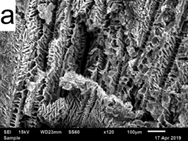
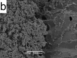
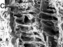
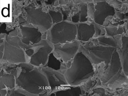
In order to study the microstructure of the aerogels, SEM photos were taken (Fig.1). As it is well known the viscosity of the precursor solution affects the final microstructure of the aerogel. The higher the concentration of the precursor solution, the more compact structure is generated [11].
PVA aerogel showed a three-dimensional architecture, which follows the direction of ice crystal growth during freezing where PVA interacts with MMT by strong hydrogen bonds. A high number of polymer fibrils connecting clay particles can be seen in figure 1a, where the main arrangement of clay following the vertical ice direction is also visible. However, some areas of the cross-section present a disordered structure owing to the radial growing of ice from the sides and its intersection with the ones coming from the bottom. During crosslinking borate ions react with the monodiol units along PVA, generating a more ordered and compact structure, which benefits the union with the superior layer [11].
In figure 1b, the cross-section of P5C5 / 8C2A (1s) composite aerogel can be observed. In the intersection between the top and bottom layers (Alginate right side, PVA left side), the different structures of the components can be seen, where the alginate/MMT layer is the one which possesses cellular microstructure and ice crystal growth orientation. The PVA/MMT displayed a continuous network structure as a result of the higher viscosity generated during crosslinking.
3.3 Compression properties
The concentration of polymer and clay play a fundamental role in the different properties of the aerogel. In terms of mechanical properties, increasing the polymer content yields an increase of modulus and strain at yield. On the other hand, in terms of flammability, decreasing the amount of polymer means less fuel content with an automatically decrease of the fire intensity. However, the above would be contradictory with optimized mechanical properties beyond a certain point. Therefore, 50% of polymer and 50% of clay has been chosen as a reference to have a balance between mechanical and fire properties.
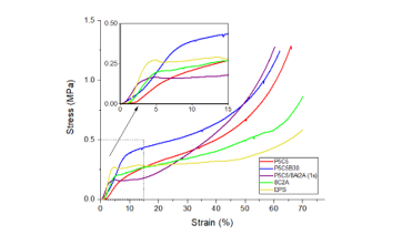
Fig. 2 shows the compressive stress-strain curves of the main aerogels studied, comparing them with expanded polystyrene (EPS). In all cases, the final deformation of the samples was between 65-70% of their original thickness. These compressive curves behave as the common deformation of elastic-plastic foams, showing a linear elastic response at low strains, followed by a plateau at intermediate strains and finally, an increment of strain is showed when the cells’ collapse occurred [14,15].
The results showed that the compressive yield stress of the P5C5B30 was higher than the P5C5 sample due to melt-crosslink procedure after 30 min in borax solution (Table 1). This aerogel exhibits better compression resistance at the same percentage of deformation and higher amount of absorbed energy, measured by the area under the curve at a certain degree of strain. It showed the absolute highest yield stress of all studied samples.
The aerogel 8C2A exhibits the closest behaviour to EPS although the recovery after compression is still higher in EPS. The plateau of the EPS is longer than the one of PVA based aerogels indicating a high resistance to collapse of the structure or in other terms a better resistance at lower applied forces.
On the other hand, the P5C5 / 8Al2A (1s) sample shows a steeper slope than that obtained by the control (P5C5) within the first 10% of deformation. Which also seems to show a more resistant microstructure since a short and well-defined plateau can be observed. This plateau apparently refers the collapse and settlement of the more fragile top layer Al(OH)3, following by the cell compaction from the bottom layer (P5C5).
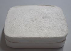
The mechanical behaviour from samples P5C5/8C2A (1s) and P5C5/8C2A (2s) was not evaluated since the top and bottom layers were not well adhered each other. This is possibly due to the little contact area between them and the slight shrinkage presented by 8C2A layer. The 8C2A was evaluated and presented a more rigid behaviour than the layer P5C5. This result can be related to the high viscosity caused by the presence of a higher amount of MMT and its dispersion on alginate.
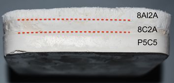
To verify if the lack of adhesion in some the bilayer samples was due to the relatively low contact area, a tri-layer composite aerogel P5C5/8C2A/8Al2A was manufactured by a single lyophilisation step. As can be seen in figure 3, very good adhesion between the different layers was obtained opening a way for creating multilayer aerogels through this method.
3.4 Thermogravimetric analysis
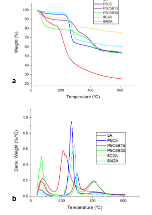
Figure 4 shows the weight loss and differential thermogravimetric curves (DTG) of the studied aerogels. Table 2 presents the main results of the analysis. Td5% is the onset temperature decomposition when 5 wt% of weight has been lost, Td max is the maximum decomposition temperature, dW/dT the maximum mass decomposition rate, and finally the residual weight (%) after the test is shown.
The decomposition peaks between 55 to 100 ºC correspond to the water absorbed due to the hygroscopic nature of the employed polymers. The second appearing peaks located in the range 210-317 ºC in Fig. 4b correspond to the decomposition of the polymers. Pure PVA thermally degrades in two steps (see Fig. 4a). The first degradation step (starting at 225 ºC) mainly involves the elimination reactions, such as chain-scission and cyclization dominating the second one (between 272 ºC and 340 ºC). A delay in the thermal decomposition can be observed in the samples cross-linked with borax. For the case of P5C5B15 aerogel, Tdmax displaced at higher temperatures (299 ºC) as compared with P5C5 (263 ºC). On the other hand, P5C5B30 decrease the dW/dT, which is a logic trend because the borax contributes to char formation limiting the heat transfer and slowing the rate of decomposition. The greater the time exposed to borax the greater was the residue left. The above also applies when MMT amount was increased.
In the TGA curves for 8C2A and 8Al2A aerogel top layers, the peaks at 40ºC -150ºC correspond to water desorption and the beginning of the destruction of glycosidic bond of alginate [16,17] at about 205ºC – 320ºC, while formation of intermediate carbonaceous char material takes place. The earlier decomposition of all samples, at 200 ºC, correspond to pure alginate where mass was rapidly lost. However, the addition of clay moves the degradation curve to higher stability. Obviously the DTG signal decreased as a result of the less amount of polymer contained in the 8C2A alginate composite.
As it can be observed that 8C2A shows much better thermal stability than P5C5 which reinforce the idea of using it as the top layer in the P5C5 / 8C2A aerogel.
| Samples | Td5% (ºC) | T d max (ºC) | dW/dT (ºC) | Residue (%) |
| P5C5 | 247 | 263 | 0.95 | 23,2 |
| P5C5B15 | 282 | 299 | 0.28 | 54,3 |
| P5C5B30 | 249 | 284 | 0.12 | 53,1 |
| 8C2A (top layer) | 246 | 254 | 0.161 | 75,4 |
| 8Al2A (top layer) | 248 | 282 | 0.651 | 60,5 |
| 5A | 183 | 209 | 0.580 | 25,3 |
| Samples | Ignition time (s) | PHRR (kW/m2) | TTPHRR (s) | THR (MJ/m2) | FIGRA (W/s) | Residue (%) |
| EPS | 0 | 414,2 | 9 | 85 | 38.4 | 0 |
| P5C5 | 0 | 142.7 | 27 | 86 | 5.29 | 42.9 |
| P5C5B15 | 0 | 131.5 | 30 | 156 | 4.38 | 43.7 |
| P5C5B30 | 11 | 166.9 | 33 | 189 | 5.06 | 43.9 |
| P5C5 / 8MMT2A (1s) | 54* | 89.4 | 180 | 99 | 0.50 | 58.5 |
| P5C5 / 8MMT2A (1s) | 51 | 94.2 | 261 | 185 | 0.36 | 47.9 |
| P5C5 / 8Al2A(1s) | 145 | 85.7 | 240 | 100 | 0.36 | 48.7 |
| 8C2A | No ignition | 6.2 | 162 | 5 | 0.04 | 67.9 |
| *Ignition delayed due to the the sample burnt from the bottom to the top layer | ||||||
3.5 Thermal conductivity
The thermal conductivity of P5C5B30 resulted in the lowest value obtained which was of 0.037 W/mK, similar to that of alginate/MMT and alginate/kaolin aerogels cross-linked by Ca2+ as reported by Ke Shang et al. [18]which showed 0.039 W/mK and 0.037 W/mK respectively. The open, tunnel-like structure of the aerogel caused by the removal of ice, limits the possibility of reaching very low values of thermal conductivity. The conductivity contribution on the solid phase basically depends on the type of polymer and its density. However, the component of thermal conductivity in the gas phase cannot be reduced because of the relatively big size of the air channels, as observed in the microstructure of the different aerogel composites. It is worth it to mention that the exposure to Borax solution had the effect of decreasing the thermal conductivities in comparison to non-cross-linked samples.
3.6 Cone calorimetry
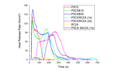
To evaluate the relative flammability of aerogels they were submitted to a cone calorimetry test. The parameters used for characterizing the aerogels were the time to ignition (TTI) peak of heat release rate (PHRR), time to peak of heat release (TTPHR), total heat release (THR) and fire growth rate (FIGRA), which is defined as the ratio of PHRR to TTPHRR and is used for evaluating the fire spread rate and flammability of the material. The results are summarized in Table 3.
The time to ignition of the PVA/MMT aerogels was instantaneous with the spark application, meaning that the concentration of combustible gases was very high. On the contrary, the aerogels containing alginate with either MMT or Al(OH)3 particles showed a much higher ignition time up to the 8C/2A sample case that did not undergo burning. This fact can be explained by the release of both water and CO2 during the decomposition of alginate [19]. On the one hand, the water lowers the temperature in the solid phase while on the other the release of CO2 decreased the concentration of oxygen to a minimum that inhibits the combustion of the polymer.
Fig. 5 illustrates the HHR of PVA /MMT aerogels with borax treatment and aerogel composites with alginate / MMT and Al(OH)3 / MMT layers. The addition of a top layer significantly decreased and delayed the PHRR of the base material, P5C5. The presence of clay generated a slow degradation and intumescence mechanism, widening the HHR curve between 120ºC and 400ºC. This fact suggests that with this top layer, the P5C5/8C2A(1s) and P5C5 / 8Al2A(1s) had a higher fire resistant in comparison to the unmodified one. However, P5C5 / 8Al2A (1s) produced more THR than P5C5/8C2A(1s). In the same way, P5C5B15 and P5C5B30 denoted a 50% increase of total heat release with respect to P5C5. Moreover, by the residual weight, it can be seen that all the samples lost between 40-60% of their initial weight, which depends on the amount of clay in each aerogel.
The release of CO2 by the alginate inhibits the origin of combustion in the gas phase and the presence of clay creates a dense barrier that reflects heat. When the clay was substituted by Al(OH)3 particles the result was similar, although the time to ignition was higher in the formed case. The release of water by the decomposition of hydroxyls in the solid phase decreased the temperature of the layer increasing in this way the ignition time. Al(OH)3 particles seemed to have a higher effect than clay in terms of delaying the fire ignition.
Comparing the FIGRA values of P5C5 (control sample) with the borax-cross-linked aerogels (P5C5B15 and P5C5B30), no significant decrease in the values was found. Contrary to the results from aerogels with P5C5 / 8C2A (1s), P5C5 / 8C2A (2s) and P5C5 / 8Al2A (1s), decreasing their FIGRA values around 10, and 14 times respectively. The above suggests that aerogels with a top layer based on Al(OH)3 exhibit almost the same burning behaviour compared other systems previously reported by L. Wang et al. [20] where the Al(OH)3 was mixed with the PVA/MMT obtaining 0.5 W/s. However, the TTPHRR of P5C5 / 8Al2A (1s) increase 90% against the time reported (27 s), which enhances the value of creating a layered aerogel
4 Conclusions
The borax crosslinking enhances the apparent densities and compactness of PVA/MMT samples structure. Although there was no variation in mechanical properties with respect to the time of exposure, a slight delayed in the thermal degradation was encountered. In regards to fire properties the crosslink, the time of ignition and TTPHRR was delayed.
The creation of a layered composite aerogel demonstrates that some properties can be also improved. For instance, the compressive behaviour of the alginate/MMT layer presented a more rigid behaviour than the PVA/MMT used as the bottom, thanks to the interaction between polymer chains with clay platelets. Also, in terms of thermal stabilization, it was demonstrated that MMT and Al(OH)3 acts as a fire retardant due to their intumescent effect. Added to that, the presence of alginate in the microstructure increases the inhibition of polymer combustion. Because it mainly decomposes in CO2 and H2O, increasing the limit concentration of oxygen needed to start fire.
Finally related to thermal conductivity no bigger differences were noted among the samples due to the similarity in internal porous microstructure. However, further investigation relating precursor viscosity, layer thickness and microstructure are necessary for achieving multi-layered flexible aerogel composites, with better mechanical, thermal and fireproofing properties for conducting more practical application.
Acknowledgments
Authors acknowledge the financial support to this work given by the Ministerio de Economía y Competitividad for the MAT2016-80045R (AEI/FEDER, UE) project. Also L.G. De la Cruz thanks to CONACyT for the grant (num. 729201) received.
References
[1] S.S. Kistler, J Phys Chem 36, pages 52-64 (1932).
[2] M.H. Nguyen, L. H. Dao, J. Non-Cryst. Solids, 225, pages 51-57 (1998).
[3] H. Tamon, H. Ishizaka, Carbon, 35, pages 791-796 (1997).
[4] C. A. Garcia-González, M. Alnajef, J Carbohydrate polymer, 86, pages 1425-1438 (2011). https://doi.org/10.1016/j.carbpol.2011.06.066
[5] K. Finlay, M. D. Gawryla, D. A. Schiraldi, J Ind. Eng. Chem. Res., 47, pages 615-619 (2008). https://doi.org/10.1021/ie0705406
[6] H. Van Olphen, Clay Miner, 15, pages 423-435 (1967).
[7] H. Van Olphen, U.S Patent, 3 203 903, (1967).
[8] .S. Somlai, S.A. Bandi, D.A. Schiraldi, American Institute of Chemical Engineers, 52, 3, pages 1162-1168 (2006). https://doi.org/10.1002/aic.10710
[9] Y. T. Wang, H. B. Zhao, K. C. Degracia, L.X. Han, H. S. Mingze Sun, Y. Z. Wang and D. A. Schiraldi, CS Appl. Mater. Interfaces, pages, 9, 42258-42265 (2017). https://doi.org/10.1021/acsami.7b14958
[10] A. E. Donius, A. Liu, L. A. Berglund, U. G. K. Wegst, J of the Mechanical Behavior of Biomedical Materials, 37, pages 88-99, (2014). https://doi.org/10.1016/j.jmbbm.2014.05.012
[11] H. B. Chen, Y. Z. Wang, M. Sánchez-Soto, D. Schiraldi, Polymer, 53, pages 5825-5831 (2012). https://doi.org/10.1016/j.polymer.2012.10.029
[12] T.J. Pinnavia, G.W. Beall, Polymer-Clay Nanocomposites (2002).
[13] B. Velde, Introduction to Clay Minerals, pages 98 – 100 (1992).
[14] M.D. Gawryla, O. Van den Berg, C. Weder, D.A. Schiraldi, J. Mat. Chem., 19, pages 2118-2124 (2009). https://doi.org/10.1039/B823218K
[15] L.J. Gibson, M.F. Ashby, Cellular solids: structure and properties Cambridge University Press (1997).
[16] J. Zhang, Q. Ji, X. Shen, Y. Xia, L. Tan, Q. Kong, J Polymer Degradation and Stability, 96, pages 936-942 (2011). https://doi.org/10.1016/j.polymdegradstab.2011.01.029
[17] J. Li, Z. Li, X. Zhao, Y. Deng, Y. Xue, J Therm. Anal. Calorim., 131, pages 2167-2177 (2018). https://doi.org/10.1007/s10973-017-6767-5
[18] K. Shang, W. Liao, J. Wang, Y.T. Wang, Y. Z. Wang and D. A. Schiraldi, ACS Appl. Mater. Interfaces, 8, pages 643-650, (2016). https://doi.org/10.1021/acsami.5b09768
[19] X. Zhang, Y. Xia, X. Yan, M. Shi, Materials Letters, 215, pages 106-109 (2018). https://doi.org/10.1016/j.matlet.2017.12.077
[20] L.Wang, M. Sánchez-Soto, M.L. Maspoch, J Materials and Design, 52 , pages 609-614, (2013). https://doi.org/10.1016/j.matdes.2013.05.096
Document information
Published on 08/05/22
Accepted on 08/05/22
Submitted on 08/05/22
Volume 03 - Comunicaciones Matcomp17 (2019), Issue Núm. 4 - País invitado: Colombia. Materiales Multifuncionales. Reciclaje y Sostenibilidad, 2022
DOI: 10.23967/r.matcomp.2022.05.009
Licence: Other
Share this document
Keywords
claim authorship
Are you one of the authors of this document?


