Abstract
Using the new modified three-fluid model, the effect of variation of inlet pressure on predictions of pressure drop in the downward condensing annular flow of steam inside vertical pipes is studied. To achieve this, using the new modified three-fluid model and Stevanovic et al.’s correlation for the steam–liquid film interfacial friction coefficient, pressure drop is calculated in two new inlet pressures (i.e., 1.5 and 2.5 (MPa)), for which there is no available experimental data of pressure drop. The pressure drop predictions of the new modified three-fluid model and those of the Stevanovic et al.’s correlation are compared.
Keywords
Condensation ; Vertical pipes ; Three-fluid model ; Annular flow ; Pressure drop ; Inlet pressure
Nomenclature
- Drag coefficient
- Pipe diameter (m)
- Virtual mass force per unit mixture volume (N m )
- Friction coefficient
- Mass flux ( )
- Gravitational constant (m s )
- Specific enthalpy (J kg )
- Latent heat of vaporization (J kg )
- Thermal conductivity (W m K )
- Length (m)
M- Mass (kg)
- Pressure (Pa)
- Volumetric heat flux (W m )
- Reynolds number ( )
- Temperature (K)
- Time (s)
- Velocity (m s )
- Coordinate (m)
- Droplets deposition rate (kg m s )
- Droplets entrainment rate (kg m s )
Greek symbols
- Evaporation/condensation rate (kg m s )
- Volume fraction
- Liquid film thickness (m)
- Dynamic viscosity (kg m s )
- Kinematic viscosity ( )
- Density (kg m )
- Surface tension (N m )
- Shear stress (N m )
Subscripts
D- Droplet
0- Initial conditions
1- Gas
2- Liquid film
3- Entrained droplets
W- Wall
1. Introduction
Internal flow condensation or condensation inside pipes has two forms [1] : condensation inside horizontal pipes and condensation inside vertical pipes. Condensation inside horizontal pipes begins with an annular flow pattern but, then, due to gravitational effect, changes into some other, usually complicated, flow patterns, such as stratified flow. However, condensation inside vertical pipes begins and ends as an annular flow pattern i.e., the flow pattern is annular in the whole process of condensation inside vertical pipes until the condensate is removed from the bottom end of the condensing pipe. In other words, annular flow pattern is the dominant flow pattern in the condensation inside vertical pipes.
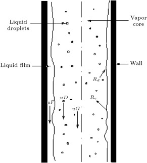
For analysis of the annular flow pattern in steam condensation inside vertical pipes, two-fluid models have been the dominant ones over the past two decades. However, some researchers have presented developed forms of two-fluid models for other two-phase flows. For instance, Chung [2] developed a new hyperbolic two-dimensional, two-fluid model to properly solve two-phase gas–liquid flows. The two-fluid models consider the pipe core gas phase and the wall-adjacent liquid film as the two fluids for which the mass, momentum and energy conservation equations are considered. Nevertheless, during the last two decades, two-fluid models have been replaced by three-fluid models, due to their compared efficiency. Three-fluid models are based on the mass, momentum and energy conservation equations for three fluid flows in the annular flow, i.e. pipe core gas phase, wall-adjacent liquid film and entrained droplets, as shown in Figure 1 . In this framework, Kishore and Jayanti [3] developed a finite volume method-based CFD model to simulate steady turbulent two-dimensional annular gas–liquid flow in a duct, in which the presence of droplets is accounted for by solving an additional scalar transport equation for the mass fraction of droplets. Alipchenkov et al. [4] suggested a three-fluid model of the dispersed-annular regime of two-phase flow that includes the equation for the number density of particles of the dispersed phase used to determine the mean particle size. Stevanovic et al. [5] predicted pressure changes in annular downward flow of condensing steam in vertical pipes with a three-fluid model. They applied several available correlations for the steam–liquid film interfacial friction in the three-fluid model, and since discrepancies were obtained between calculated and measured pressure changes, they proposed a new correlation for the interfacial friction coefficient, which provided good agreement.
|
|
|
Figure 1. The annular flow for condenstation inside a vertical pipe. |
Although the proposed correlation by Stevanovic et al. [5] for the steam–liquid film interfacial friction coefficient provides good agreement with measured data of pressure changes, it has some deficiencies. Saffari and Dalir [6] investigated one of the deficiencies of the available three-fluid models, i.e. lack of consideration for the friction stress of droplets with liquid film. They studied the effect of the friction stress of droplets with film on the prediction of pressure drops, and concluded that, by taking into account the droplets–film friction stress, the agreement of calculated pressure drop with experimental data improved by approximately 30% compared to the agreement of Stevanovic et al.’s [5] correlation with experimental data. Further, Saffari and Dalir [7] named the lack of consideration of the virtual mass force term as another deficiency in the available three-fluid models, and by inclusion of the virtual mass force in the conservation equations, they obtained 10% more agreement in their results with measured data compared to Stevanovic et al.’s [5] correlation. They called their new model a new modified three-fluid model, which is the Stevanovic et al.’s [5] correlation for the steam–liquid film interfacial friction coefficient with two corrections; use of the droplets–film friction stress and introduction of the virtual mass force term.
Condensation inside vertical pipes often occurs in steam condensers within passive nuclear reactors [8] . In the design of a steam condenser pipe within a passive reactor, an important factor is the provision of enough pressure drops along the pipe flow for the purpose of taking out the condensed steam from the pipe outlet to the water tank [9] . The reason is that in cases where this needed pressure drop is not provided, the amount of condensed steam will increase at the outlet parts of the pipe, resulting in the reduction of condensation surface and finally blocking the whole condensation process.
In the present paper, using the new modified three-fluid model, the effect of variation of inlet pressure on pressure drop predictions in the downward condensing annular flow of steam in vertical pipes is investigated. To do this, the pressure drops are calculated in two new inlet pressures, i.e. and 2.5 (MPa), for which there is no available experimental data of pressure drop, using the new modified three-fluid model: Stevanovic et al.’s [5] correlation with corrections, and Stevanovic et al.’s [5] correlation for the steam–liquid film interfacial friction coefficient. The predictions of pressure drops using the new modified three-fluid model and Stevanovic et al.’s [5] correlation are obtained and discussed.
2. Governing equations and closure relations
The conservation equations of mass, momentum, and energy, written for each of three fluids, i.e., the gas (vapour) core, the wall-adjacent liquid film and the dispersed phase (entrained droplets) flowing inside the gas phase, comprise the base of three-fluid models for annular flow. The conservation equations of mass, momentum and energy for two-phase annular flow of a three-fluid model in a circular pipe have the following forms [4] , [5] , [6] and [7] :
Conservation equations of mass:
|
|
( 1) |
Conservation equations of momentum:
|
|
( 4) |
Conservation equations of energy:
|
|
( 7) |
The equation for the volume balance is as follows:
|
|
( 10) |
The closure and constitutive relations include:
- Rate of droplets deposition [10] :
|
|
( 11) |
- Rate of droplets entrainment [10] :
|
|
( 12) |
- Wall-film shear stress [11] :
|
|
( 13) |
- Gas phase-droplets shear stress [12] :
|
|
( 14) |
- Mean droplet diameter:
|
|
( 15) |
- Liquid film–gas phase shear stress:
|
|
( 16) |
- Stevanovic et al.’s [5] correlation for :
|
|
( 17) |
- Rate of condensation [13] :
|
|
( 18) |
- Rate of evaporation [13] :
|
|
( 19) |
- Gas phase, liquid film and entrained droplets Reynolds numbers:
|
|
( 20) |
It should be mentioned that other correlations for the gas phase–liquid film interfacial friction coefficient , i.e. modified Wallis, Levitan and Alipchenkov correlations, and also details of the closure relations presented above can be found in other studies, such as [5] , [6] and [7] .
3. The new modified three-fluid model
In the new modified three-fluid model, developed by authors of the present paper, Stevanovic et al.’s [5] correlation is used for the steam–liquid film interfacial friction coefficient. However, in the new modified three-fluid model, two corrections are applied, which are neglected by all previously developed three-fluid models:
- the virtual mass (added mass) force term is taken into account, and
- the friction stress of droplets with liquid film is considered.
3.1. Virtual mass force
The virtual mass (added mass) force is considered only in multiphase flows, where two of the phases accelerate or decelerate, with respect to one another. In the case of condensation inside vertical pipes, the two phases accelerating or decelerating with respect to each other are entrained droplets and gas phase, and, thus, the virtual mass force quantifies the effect of the entrained droplet velocity on the gas phase velocity. A virtual mass force relation for steady one-dimensional annular flow is as follows [13] :
|
|
( 21) |
3.2. Droplets–film friction stress
The friction stress of droplets with film is caused by the turbulent fluctuations of the entrained droplets and gas phase velocities. Thus, to obtain the droplets–film friction stress, the correlation between the intensities of turbulent fluctuations of the entrained droplets and gas phase velocities is used, which gives [14] :
|
|
( 22) |
where is the coefficient of the droplets response to the turbulent velocity fluctuations of the gas phase, and is given as [15] :
|
|
( 23) |
It should be mentioned that the details of Eqs. (22) –(23) are lengthy and can be found in [4] and [6] .
4. Solution methodology
The conservation equations of mass, momentum and energy, i.e. Eqs. , , , , , , , and , are considered for each of three fluids in steady-state one-dimensional form, in which the one dimension is the pipe length direction. Then, doing some mathematical manipulation, the conservation equations and volume balance equation are altered to ten first-order nonlinear ordinary differential equations (ODEs), giving the derivatives of ten unknowns. Since the ODEs are coupled, they should be solved together as a system of ODEs. In order to solve the ODE system, numerical integration is applied using MatLab ODE solver, i.e. ode23s. The reason for using ode23s, and not ode23, is that there are parameters in the problem with a large rage of changes, such as pressure, along with parameters with a small range of changes, such as volume fraction. Thus, the condensation problem inside the vertical pipes is stiff. It should be mentioned that the operator ode23s uses Rozenbrook ODE solvers to solve a system of ODEs. In other words, ode23s is based on the Rozenbrook modified second order formula, which evaluates solution in a new step, using , where is obtained by solving -number of linear algebraic equations [16] . It should also be noted that in the numerical integration procedure, the initial conditions are flow parameters at the pipe inlet. Therefore, the ten ODEs are implemented in a MatLab code and solved as an initial value problem.
5. Results and discussion
A MatLab code is written to numerically obtain pressure drops in the condensing vertical pipes using the new modified three-fluid model. The pressure drop predictions are verified by the experimental data of Kreydin et al. [17] , which are for a pipe of diameter (m) and length (m).
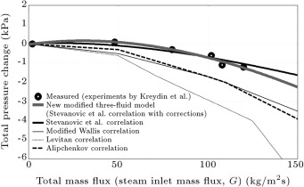
The experimental and calculated total pressure changes, in terms of the total mass flux , for various gas phase–liquid film interfacial friction coefficient correlations at an inlet pressure of 1.08 (MPa), are indicated in Figure 2 , which is taken from [6] . It can be seen that the best match with experimental data is provided by the new modified three-fluid model, and although the Stevanovic et al.’s [5] correlation also provides a good match with experiments, it is not as good as the new modified three-fluid model.
|
|
|
Figure 2. Predictions of the new modified three-fluid model compared with experimental data at inlet pressure of 1.08 (MPa) (Saffari and Dalir, 2011). |
If three momentum conservation equations for three fluids, Eqs. , and , are summed up, it gives:
|
|
( 24) |
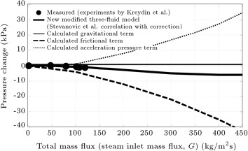
which means that total pressure change includes three terms: frictional, gravitational and acceleration. The first term on the right-hand side of Eq. (24) indicates frictional pressure change, the second term indicates gravitational pressure change, and the third term indicates acceleration pressure change. Figure 3 , also taken from [6] , demonstrates the various pressure change terms for the steam inlet pressure of 1.08 (MPa) using the new modified three-fluid model. It is seen that for inlet mass flux values lower than 60 (kg m−2 s−1 ), i.e. the low mass flux range, the gravitational pressure change term has dominancy. Thus, as the gravitational pressure change is always positive for the downward condensing flow of steam, the pressure increases along the flow from the inlet to the outlet of the pipe in the low mass flux range. It is also observable that if the total mass flux increases in the low mass flux range ( (kg m−2 s−1 )) such that it does not become higher than 60 (kg m−2 s−1 ), the (positive) total pressure change boosts. For inlet mass flux values higher than 60 (kg m−2 s−1 ), i.e., the high mass flux range, the frictional pressure change term has dominancy. Therefore, as the frictional pressure change is negative for downward condensing flow, the pressure reduces along the flow from the inlet to the outlet of the pipe. It is also clear that in the high mass flux range ( (kg m−2 s−1 )), the (negative) total pressure change increases with an increase in total mass flux.
|
|
|
Figure 3. Predictions of the new modified three-fluid model compared with experimental data along with pressure drop terms at inlet pressure of 1.08 (MPa) (Saffari and Dalir, 2011). |
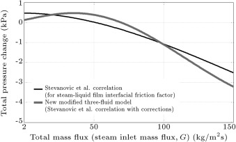
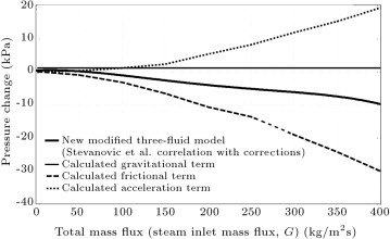
In Figure 4 , total pressure changes, in terms of total mass fluxes, are presented for the inlet pressure of 1.5 (MPa), for which there is no available experimental data. As the new modified three-fluid model and the Stevanovic et al.’s [5] correlation provided the best match with experimental data in the case of 1.08 (MPa) inlet pressure, only they are used to calculate pressure changes in the 1.5 (MPa) inlet pressure case. Figure 5 shows the pressure change terms in the inlet pressure of 1.5 (MPa) using the new modified three-fluid model. It can be seen from the curves of the new modified three-fluid model in Figure 4 and Figure 5 that for total mass flux values lower than 70 (kg m−2 s−1 ), the total pressure change is positive, i.e. pressure boosts along the flow from the inlet to the outlet of the pipe due to the domination of the gravitational pressure change term. It is also viewed that the (positive) total pressure change increases when the total mass flux increases in the low mass flux range ( (kg m−2 s−1 )). However, the total pressure change is negative, i.e., the pressure reduces along the flow from the inlet to the outlet of the pipe for total mass flux values higher than 70 (kg m−2 s−1 ). The reason is that, here, the frictional pressure change term has dominancy. It is also observable that if the total mass flux increases in a high mass flux range ( (kg m−2 s−1 )), the (negative) total pressure change enhances.
|
|
|
Figure 4. Predictions of the new modified three-fluid model compared with predictions of Stevanovic et al.’s correlation at inlet pressure of 1.5 (MPa). |
|
|
|
Figure 5. Predictions of the new modified three-fluid model along with pressure drop terms at inlet pressure of 1.5 (MPa). |
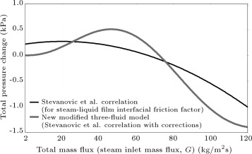
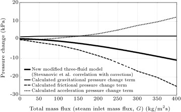
Figure 6 shows the total pressure changes in terms of the total mass fluxes for the inlet pressure of 2.5 (MPa), with no available experimental data. Here, in the 2.5 (MPa) inlet pressure case, again, the new modified three-fluid model and Stevanovic et al.’s [5] correlation are used to calculate the pressure changes. Figure 7 presents the pressure change terms in the inlet pressure of 2.5 (MPa) using the new modified three-fluid model. It can be viewed from the new modified three-fluid model curves in Figure 6 and Figure 7 , which, for total mass fluxes lower than 75 (kg m−2 s−1 ), the total pressure change is positive because the gravitational pressure change term is dominant. It is also seen that in the low mass flux range ( (kg m−2 s−1 )), the (positive) total pressure change increases with the increase of the total mass flux. Nevertheless, at total mass fluxes higher than 75 (kg m−2 s−1 ), the total pressure change is negative, i.e. pressure decreases from pipe inlet to outlet. The reason is that, here, the frictional pressure change term is dominant. It is also observed that the (negative) total pressure change shows an increase with an increase in total mass flux at high mass flux range ( (kg m−2 s−1 )).
|
|
|
Figure 6. Predictions of the new modified three-fluid model compared with predictions of Stevanovic et al.’s correlation at inlet pressure of 2.5 (MPa). |
|
|
|
Figure 7. Predictions of the new modified three-fluid model along with pressure drop terms at inlet pressure of 2.5 (MPa). |
Figure 2 , Figure 3 , Figure 4 , Figure 5 , Figure 6 and Figure 7 make it clear that when the steam inlet pressure has values of 1.08 (MPa), 1.5 (MPa) and 2.5 (MPa), the boundary mass flux of low and high mass flux ranges have values of 60 (kg m−2 s−1 ), 70 (kg m−2 s−1 ) and 75 (kg m−2 s−1 ), respectively. Here, it is worth mentioning that for mass fluxes lower than the boundary mass flux, the gravitational pressure change has dominancy, and for mass fluxes higher than the boundary mass flux, frictional pressure change has dominancy. Thus, it can be concluded that the higher the condensing pipe inlet pressure, the higher the boundary mass flux of low and high mass flux ranges. This is due to the fact that with the inlet pressure increase, the gravitational pressure change boosts, but the frictional pressure change reduces.
It can be seen from Figure 2 , Figure 4 and Figure 6 that at the constant total mass flux of 100 (kg m−2 s−1 ), for inlet pressures of 1.08 (MPa), 1.5 (MPa) and 2.5 (MPa), the total pressure changes have values of (kPa), (kPa) and (kPa), respectively. Thus, it is reasonable to say that the increase in inlet pressure at a constant mass flux in the high mass flux range causes a reduction in the magnitude of total pressure change.
In condensing vertical pipes, such as those in steam condensers within passive nuclear power reactors, adequate pressure drops should be provided in order to take out the condensed steam from the outlet of the pipe. Thus, the provision of a positive pressure drop is essential. Here, Figure 2 , Figure 3 , Figure 4 , Figure 5 , Figure 6 and Figure 7 can help to figure out the range of the inlet mass flux with positive pressure drop and, thus, to choose the value of the inlet mass flux for particular cases of application. Consequently, in the industrial use of vertical condensing pipes, such as passive reactors, an inlet mass flux is required for a specified total pressure drop. Figure 4 , Figure 5 , Figure 6 and Figure 7 can be very helpful in determining the required values of inlet mass fluxes at inlet pressures of 1.5 (MPa) and 2.5 (MPa).
6. Conclusions
The influence of variations of inlet pressure on pressure drop predictions of the condensing annular flow of steam in vertical pipes is investigated using the new modified three-fluid model and Stevanovic et al.’s [5] correlation. The pressure drops were previously calculated at an inlet pressure of 1.08 (MPa), for which the experimental data of Kreydin et al. [17] are available. However, in the present paper, pressure drops are calculated at inlet pressures of 1.5 and 2.5 (MPa) for which there is no available experimental data. The conservation equations, considered for each of three fluids in steady 1-D forms, and the volume balance equation, are altered to a system of ten first-order ODEs. Then, by writing a MatLab code, using MatLab stiff ODE solver, i.e. ode23s, numerical integration is applied to solve the ODE system, for which the initial conditions are flow parameters at the pipe inlet. The following results are obtained:
- At the inlet pressure of 1.08 (MPa), the new modified three-fluid model provides a much better match with experimental data compared to all other correlations.
- The boundary mass flux of the low and high mass flux ranges increases with the increase of inlet pressure in condensing vertical pipes.
- At a constant high mass flux in a vertical pipe with steam condensation, when the inlet pressure increases, the magnitude of total pressure change decreases.
- In condensing vertical pipes in passive reactors, a specified amount of total pressure drop requires a specific amount of steam inlet mass flux, in determination of which the presented new modified three-fluid model can be very helpful at 1.5 and 2.5 (MPa) inlet pressures.
References
- [1] S.G. Kandlikar, M. Shoji, V.K. Dhir; Handbook of Phase Change: Boiling and Condensation; Taylor & Francis, UK (1999), p. 621
- [2] M.S. Chung; Characteristic development of hyperbolic two-dimensional two-fluid model for gas–liquid flows with surface tension; Appl. Math. Model., 31 (2007), pp. 578–588
- [3] B.N. Kishore, S. Jayanti; A multidimensional model for annular gas–liquid flow; Chem. Eng. Sci., 59 (2004), pp. 3577–3589
- [4] V.M. Alipchenkov, R.I. Nigmatulin, S.L. Soloviev, O.G. Stonik, L.I. Zaichik, Y.A. Zeigarnik; A three-fluid model of two-phase dispersed-annular flow; Int. J. Heat Mass Transfer, 47 (2004), pp. 5323–5338
- [5] V.D. Stevanovic, M. Stanojevic, D. Radic, M. Jovanovic; Three-fluid model predictions of pressure changes in condensing vertical tubes; Int. J. Heat Mass transfer, 51 (2008), pp. 3736–3744
- [6] H. Saffari, N. Dalir; Effect of friction stress of droplets with film on prediction of pressure changes in condensing tubes; Sci. J. Mech., 17 (1) (2011), pp. 50–56
- [7] H. Saffari, N. Dalir; Effect of virtual mass force on prediction of pressure changes in condensing tubes; Therm. Sci. J., 16 (2) (2012), pp. 613–622
- [8] S.J. Kim, H.C. No; Turbulent film condensation of high pressure steam in a vertical tube; Int. J. Heat Mass Transfer, 43 (2000), pp. 4031–4042
- [9] A.S. Dalkilic, S. Wongwises; Intensive literature review of condensation inside smooth and enhanced tubes; Int. J. Heat Mass Transfer, 52 (2009), pp. 3409–3426
- [10] S. Sugawara; Droplet deposition and entrainment modeling based on the three-fluid model; Nucl. Eng. Des., 122 (1990), pp. 67–84
- [11] F.M. White; Viscous Fluid Flow, pp. 117 and 422; McGraw-Hill, New York, US (1991)
- [12] R. Clift, J.R. Grace, M.E. Weber; Bubbles, Drops and Particles; Academic Press, New York, US (1978), p. 111
- [13] S.M. Ghiaasiaan; Two-Phase Flow, Boiling and Condensation in Conventional and Miniature Systems; (1st Edn.)Cambridge University Press, UK (2008), pp. 137–169
- [14] J.O. Hinze; Turbulence; McGraw-Hill, New York, US (1975), p. 453
- [15] L.I. Zaichik, V.M. Alipchenkov; Interaction time of turbulent eddies and colliding particles; Thermophys. Aeromech., 6 (1999), pp. 493–501
- [16] B.D. Hahn, D.T. Valentine; Essential MatLab for Engineers and Scientists; Elsevier Ltd, London, New York, Oxford (2007), p. 376
- [17] B.L. Kreydin, I.L. Kreydin, V.A. Lokshin; Experimental research of the total pressure drop in the condensing steam downward flow inside a vertical tube; Therm. Eng., 32 (1985), pp. 42–43
Document information
Published on 06/10/16
Licence: Other
Share this document
Keywords
claim authorship
Are you one of the authors of this document?
