Abstract
Laser bending is a process of gradually adding plastic strain to a metal component to generate desired shape. In this paper, laser bending of tailor machined blanks has been investigated experimentally. For this purpose, effects of start point of scan path and also irradiation direction relation to step (position of variance in sheet thickness) of the tailor machined blank on the obtained bending angles are investigated. The results show that irradiation path from rim of thick section to rim of thin section of the tailor machined blank leads to more bending angles in comparison with irradiation path from thin section to thick section of tailor machined blank. Also, it is concluded from results that when the step of tailor machined blank is positioned in the opposite direction to the laser beam, more bending angles are obtained in the laser formed tailor machined blank in comparison with positioning of step of tailor machined blank toward the laser beam. The results indicate that the bending angle of tailor machined blank is increased with increasing the laser output power and decreasing the laser scanning speed.
Keywords
Tailor machined blanks; Laser bending; Start point of scan path; Irradiation direction relation to step
1. Introduction
Laser bending is a flexible forming process that needs no hard tooling or external forces. It is used in some industrial applications such as shipbuilding, automobile, microelectronics and aerospace. In laser bending, a sheet is irradiated with a defocused laser beam. Thereby inducing rapid localized heating followed by cooling as the laser beam moves on to an adjacent area. In the heating stage, if the thermal strains in the irradiated zone exceed the elastic limit, then these strains are converted into plastic compressive strains. In the cooling stage, the sheet will undergo shrinkage and therefore a complex shape of the work-piece can be formed. For the first time in 1986, Namba [1] used laser beam as a tool for sheet metal forming. After Namba, many researchers have done a lot of works in the laser bending of sheet metals. In 1993, Geiger and Vollertsen [2] identified three key mechanisms called temperature gradient mechanism (TGM), buckling mechanism (BM) and upsetting mechanism (UM) to explain the thermo-mechanical behavior in laser bending based on geometrical and laser beam parameters. Also, in 2003, Steen [3] reported that for TGM to occur Fourier number i.e. , (where and are the thermal diffusivity of material, beam diameter, sheet thickness and scan speed respectively) should be much lesser than unity whereas for BM and UM to occur it is the opposite. In 2001, Li and Yao [4] proposed a new scanning scheme with starting point from the middle of the work-piece and then they produced a convex shape plate. In 2006, Shen et al. [5] in a numerical work used two simultaneous laser beams along two parallel lines. They concluded that if the distance between two laser beams is not too large then plastic deformation generated in this state is larger than that generated by single sequential scans along the same lines. In 2006 and 2007, Shen et al. [6] and [7] investigated the effects of time intervals and overlapping on bending angles in laser bending using two simultaneous laser beams numerically. It is reported by some authors that geometric effects, especially due to thickness, play an important role in the laser forming. In 2005, Cheng et al. [8] proposed an analytical model to predict bending variation due to change of plate size (width and length). In all of the above references, a plate with uniform thickness was considered and studies cannot be applied to varying thickness plate. In recent years, a few researches have been done on the laser forming of varying thickness plates. In 2006, Cheng et al. [9] in a study using experimental, numerical and analytical methods investigated the effects of bending mechanism and process parameters on the deformation characteristics in the laser forming of varying thickness plates. They found a transition of the laser forming mechanism along the scanning path when the thickness varies. In their work, the effect of scanning speed, laser beam diameter and multiple scanning on the bending angle was investigated. Also, it was shown that proposed analytical model in their work can predict the bending angle and angle variations for laser forming of varying thickness plates. Also in 2006, Cheng et al. [10] using a strain-based strategy investigated the laser forming process for thin plates which varying thickness. Their proposed strategy was utilized in determining the scanning paths and the proper heating conditions. They showed that in the laser forming of varying thickness plates, both the in-plane and bending strains are needed to be accounted for in process design. Tailor-made blanks are sheet metal assemblies with different thicknesses and/or materials and/or surface coatings. These blanks can be made by welding or bonding or machining processes. A monolithic sheet can be machined to make the required thickness variations. The tailor made blanks that have been made by machining process are referred as tailor machined blanks. With tailor machined blanks, distribution of material within the structural parts used in the aircraft and automotive industries has been improved and therefore more cost effective, fuel effective and lighter vehicles can be made. Both laser bending and tailor machined blanks have been introduced recently and the aim of present work is studying the laser bending of tailor machined blank.
In a tailor machined blank, presence of two different thicknesses in one single assembly causes different forming behaviors such as different bending angles and curvatures in various sections of the blank. Due to thickness variations in tailor machined blanks, laser bending of these blanks is more difficult than laser bending of monolithic plates. However, bending angles in tailor machined blanks can be contrasted to the bending angle for constant thickness (monolithic) plates.
In this paper, laser bending of tailor machined blanks has been investigated experimentally. For this purpose, effects of start point of scan path and also irradiation direction relation to step (position of variance in sheet thickness) of the tailor machined blank on the obtained bending angles are investigated.
2. Experimental work
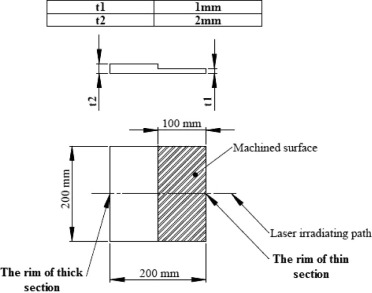
The dimensions of the tailor machined blank used in this paper and its irradiating path are shown in Fig. 1. The samples were made from mild steel with 200 mm (length) × 200 mm (width) × 4 mm (thickness). To prepare a tailor machined blank, firstly 1 mm of both sides of initial sheet were machined and a sheet with thickness of 2 mm was obtained. Then, half part of plate was machined to 1 mm by milling process. Milling process will produce residual stresses in the tailor machined blanks and therefore the specimens should be stress relieved. For this purpose, stress relieving heat treatment was performed and according to Ref. [11] the blanks were put in a furnace at a temperature of 500 °C for about one hour. After removing from the furnace, the specimens were air cooled in still air. Laser bending experiments were carried out with a continuous AMADA laser with the maximum power of 2000 W. In the experiments, laser output power, laser scanning speed and laser beam diameter are adjusted as 1000 W, 30 mm/s and 6 mm, respectively. Also, laser focus location is adjusted at 4 mm above the surface of the sheet in thin section. However, in order to reduce the variation of laser beam diameter in thin and thick sections of the tailor machined blank, a lens with large focal length (190 mm) is used. During laser bending process, temperatures of various points are recorded with an infrared laser thermometer (Model: IRTEK IR190G). For this purpose, the infrared thermometer is placed at a distance of 5 mm from the top surface of tailor machined blank. For example, in order to measuring the temperature of sample point A, the thermometer is adjusted in 5 mm from the top surface of tailor blank at line of abrupt thickness change or intersection of two thick and thin sections. In this position, the thermometer can accurately measure the temperature of sample point A.
|
|
|
Figure 1. Dimensions of tailor machined blank and laser beam irradiating path. |
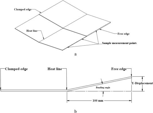
Deformation of the samples was measured using a coordinate measuring machine (CMM) at 11 locations along the scanning path. In Fig. 2a, a schematic of laser formed tailor machined blank is shown. The clamped edge, heat line, free edge and some measurement points are shown in this figure. Also in Fig. 2b, a schematic of bending angle relevant to Y-displacement of each measurement point on the free edge is shown. Bending angle of each measurement point can be calculated as follows:
|
|
|
|
|
Figure 2. Schematic shape of laser formed tailor machined blank, (a) clamped edge, free edge, heat line and sample measurement points, (b) calculation of bending angle from displacement. |
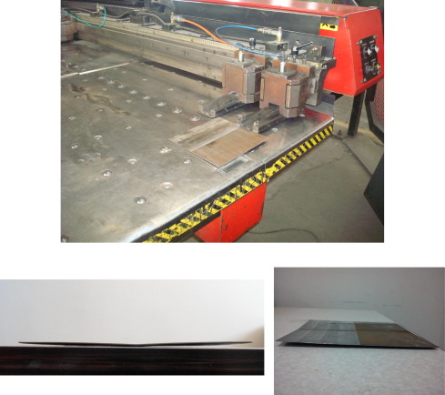
In Fig. 3, experimental setup for laser bending of tailor machined blank and formed specimens are shown.
|
|
|
Figure 3. Experimental setup for laser bending of tailor machined blank and formed specimens. |
3. Results and discussion
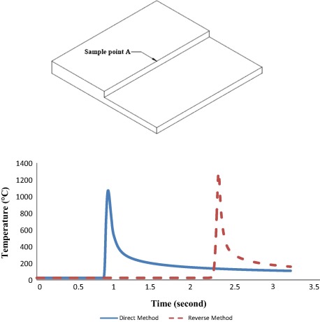
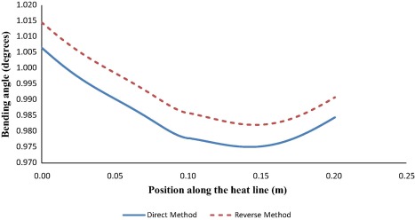
In this section, first the results of the effect of scan path direction on obtained bending angle in the laser bending of tailor machined blanks are presented. It must be mentioned that in this paper, laser bending with start point of scan path at the rim of thin section of tailor machined blank is referred as Direct Method and laser bending with start point of scan path at the rim of thick section of tailor machined blank is referred as Reverse Method. In Fig. 4, temperature profiles of sample point A for Direct and Reverse Methods at the end of heating step are shown. As it is seen in this figure, peak temperature of sample point A for Reverse Method is higher than Direct Method. The reason is that sample point A in the Direct Method positioned at the first irradiated edge of the thick section while in the Reverse Method positioned at the exit irradiated edge of the thick section. Obviously peak temperature of sample point A in the Reverse Method is higher than Direct Method. Because in the laser bending process, heat imparted into the plate as the laser beam traverses across it, is continually flowing into the cold region ahead of the beam. This phenomenon is occurred for sample point A in the Direct Method. In the Reverse Method, as the sample point A is positioned in the exit irradiated edge, the heat flowing ahead of the beam cannot travel any further and so a heat buildup occurs. Hence the peak temperature increases at the exit edge. However, in the Reverse Method more plastic areas are created in the intersection of thin and thick sections than the Direct Method. Therefore, in the Reverse Method dominant mechanism in the intersection of thin and thick sections is buckling mechanism due to more plastic areas while in the Direct Method dominant mechanism in the intersection is temperature gradient mechanism (TGM). As the intersection of thin and thick sections is the more critical area of tailor machined blank, therefore variations in its dominant deformation mechanism directly affect the global bending angle of laser formed tailor machined blank.
|
|
|
Figure 4. Temperature profile of sample point A for Direct Method and Reverse Method at the end of heating step, Direct Method = irradiating from thin section to thick section; Reverse Method: irradiating from thick section to thin section. |
In Fig. 5, obtained bending angles of tailor machined blank for Direct and Reverse Methods are shown and compared. As it is seen, obtained bending angle by Reverse Method is larger than obtained bending angle by Direct Method. The reason is that temperature of the intersection line of thin and thick sections, for Reverse Method is higher than Direct Method and therefore resulted bending angle for Reverse Method is higher than Direct Method. Also, it should be noted that irradiated energy per unit volume in the thick section of tailor machined blank is small in comparison with thin section and consequently the resulted bending angle in the thick section is also smaller than the thin section. Therefore, different bending angles in the thin and thick sections of tailor machined blank leads to a concave curve shape of bending angle.
|
|
|
Figure 5. Obtained bending angles along the heat line of tailor machined blank for Direct Method and Reverse Method, Direct Method = irradiating from thin section to thick section; Reverse Method: irradiating from thick section to thin section. |
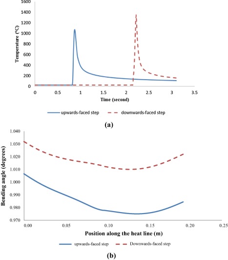
In the following, the results of the effect of irradiation direction relation to step of tailor machined blank on the obtained bending angle are presented. It must be mentioned that in this paper, when the step is on the upward facing surface it is referred as upwards-faced step and consequently when the step is on the downward facing surface it is referred as downwards-faced step. In Fig. 6, obtained bending angles from laser bending of a tailor machined blank that is positioned upwards-faced step are compared with obtained bending angles from laser bending of a tailor machined blank that is positioned downwards-faced step. As it is seen from Fig. 6, bending angle obtained from downwards-faced step is larger than upwards-faced step. The reason is that in the upwards-faced step, heat transfer of irradiated surface due to convection in the intersection of thin and thick sections occurs from two free surfaces while in the downwards-faced step, heat transfer of irradiated surface due to convection in the entire of scan path occurs from one free surface. Therefore, heat loss in the intersection of thin and thick sections for upwards-faced step is more than heat loss in the downwards-faced step. However, as the peak temperature of intersection of thin and thick sections in the downwards-faced step method is more than upwards-faced step, then resulted plastic deformations and consequently bending angle is larger for downwards-faced step method.
|
|
|
Figure 6. Obtained temperature profiles and bending angles of tailor machined blank for upwards-faced step method and downwards-faced step method; (a) temperature profiles for a node placed at intersection of thin and thick sections, and (b) bending angels along the heat line. |
In the following, the effects of laser output power and laser scanning speed on obtained bending angle in the laser bending of tailor machined process are investigated. It should be noted that in the following sections, irradiating direction is from thin to thick sections (Direct Method) and also the step is positioned on the upward facing surface (upwards-faced step method).
3.1. Effect of laser output power on bending angle
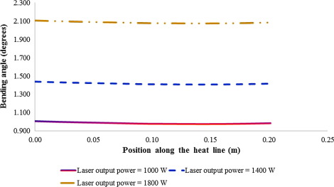
For investigating the effect of laser output power on the bending angle, some experiments are performed. In these tests, laser output power is adjusted as 1000, 1400 and 1800 W, whereas laser beam diameter and laser scanning speed are constant (laser beam = 6 mm and laser scanning speed = 30 mm/s). The effects of laser power on bending angle of laser bent tailor machined blank are shown in Fig. 7. As it is concluded from this figure, the bending angle of tailor machined blank is increased with increasing the laser output power. The reason is that with increasing the laser power, induced heat flux into the plate is increased and therefore plastic deformation areas in the plate are increased. Also, it is seen from Fig. 7 that with increasing the laser output power, the rate of increase in the bending angle is increased. This is due to change in the dominant mechanism of laser bending in the thick section of tailor machined blank with increase in the laser power. As with increase in the laser power, more heat fluxes are induced into the plate, therefore dominant mechanism in the thick section of the tailor machined blank trends to buckling mechanism. Also, bending stiffness of thick section is larger than the bending stiffness of thin section. Therefore, deformation of thick section affects the deformation of thin section. Hence, bending angle of thick section is increased that leads to increase in the final bending angle of tailor machined blank.
|
|
|
Figure 7. Obtained bending angles along the heat line of tailor machined blank with different laser output powers, laser scanning speed = 30 mm/s and laser beam diameter = 6 mm. |
3.2. Effect of laser scanning speed on bending angle
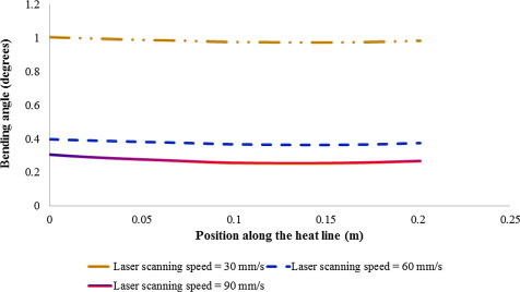
In the tests of investigation of the effect of laser scanning speed, laser output power and laser beam diameter are adjusted as 1000 W and 6 mm, respectively while the laser scanning speed is changed (laser scanning speed is adjusted as 30, 60 and 90 mm/s). In Fig. 8, the results of obtained bending angle of laser bent tailor machined blank for different values of laser scanning speed are indicated. As it is seen from this figure, it is seen that the bending angle of laser bent tailor machined blank is decreased with increasing the laser scanning speed. The reason is that with increasing the laser scanning speed, induced heat flux into the plate is decreased. Also, it should be noted that due to different scanning speeds in the thin and thick sections of tailor machined blank, there are different combinations of laser bending mechanisms in the thin and thick sections. If the Fourier number is used to approximately estimate the laser forming mechanism, it will be found that for laser scanning speeds of 30, 60 and 90 mm/s, Fourier number in the thin section (, , ) is calculated as 2.36, 1.58 and 1.05, respectively. These Fourier values prove dominant forming mechanism in the thin section of the tailor machined blank is buckling mechanism (BM). However, for laser scanning speeds of 30, 60 and 90 mm/s, Fourier number in the thick section (, ) is calculated as 0.79, 0.39 and 0.26, respectively. Calculated Fourier number for laser scanning speed of 90 mm/s shows that dominant bending mechanism in the thick section of tailor machined blank is temperature gradient mechanism (TGM). With TGM mechanism, plastic deformation area, in other words the resulted bending angle is small. As it is mentioned in the previous section, deformation of the thick section seriously affects the bending angle of the thin section and consequently the overall bending angle of the tailor machined blank. In the laser scanning speed of 90 mm/s, since irradiated energy per unit volume is small, consequently the resulted bending angle in the thick section is also small. Hence bending angle of tailor machined blank is small. According to obtained Fourier number for laser scanning speed of 60 mm/s, it can be concluded that the dominant mechanism in the thick section is TGM. However, due to induction more heat flux into the plate than laser scanning speed of 90 mm/s, plastic deformation area in the thick section is increased and thus the resulted bending angle of tailor machined blank increases. Obtained Fourier number for laser scanning speed of 30 mm/s proves that dominant mechanism in the thick section is buckling mechanism (BM). In this condition plastic deformation area in the thick section is noticeably increased and therefore obtained bending angle in tailor machined blank is considerably increased in comparison with laser scanning speeds of 60 and 90 mm/s.
|
|
|
Figure 8. Obtained bending angles along the heat line of tailor machined blank with different laser scanning speeds, laser output power = 1000 W and laser beam diameter = 6 mm. |
4. Conclusion
In this paper, the effects of start point of scan path and also irradiation direction relation to step (position of variance in sheet thickness) of the tailor machined blank on the obtained bending angles were investigated. For this purpose, using a continuous AMADA laser with the maximum power of 2000 W, experimental investigations were performed. Laser bending with start point of scan path at the rim of thin section of tailor machined blank was referred as Direct Method and laser bending with start point of scan path at the rim of thick section of tailor machined blank was referred as Reverse Method. Also, positioning of the step of tailor machined blank toward the laser beam was referred as upwards-faced step and also positioning of the step of tailor machined blank in the opposite direction to the laser beam was referred as downwards-faced step. Following results were obtained:
- The results showed that obtained bending angle by Reverse Method was larger than obtained bending angle by Direct Method. The reason was that temperature of the intersection line of thin and thick sections, for Reverse Method was higher than Direct Method and therefore resulted bending angle for Reverse Method was higher than Direct Method.
- The results showed that bending angle obtained from downwards-faced step is larger than upwards-faced step. The reason is that in the upwards-faced step, heat transfer of irradiated surface due to convection in the intersection of thin and thick sections occurs from two free surfaces while in the downwards-faced step, heat transfer of irradiated surface due to convection in the entire of scan path occurs from one free surface. Therefore, heat loss in the intersection of thin and thick sections for upwards-faced step is more than heat loss in the downwards-faced step.
- It was concluded from results that the bending angle of tailor machined blank was increased with increasing the laser output power. The reason was that with increasing the laser power, induced heat flux into the plate was increased and therefore plastic deformation areas in the plate were increased. Also, it was proved that with increasing the laser output power, the rate of increase in the bending angle was increased. This was due to change in the dominant mechanism of laser bending in the thick section of tailor machined blank with increase in the laser power.
- It was indicated that the bending angle of laser bent tailor machined blank was decreased with increasing the laser scanning speed. The reason was that with increasing the laser scanning speed, induced heat flux into the plate was decreased. Also, it could be resulted that with decreasing the laser scanning speed, dominant mechanism in the thick section of tailor machined blank tend to buckling mechanism and however this leads to obtaining higher bending angles in the tailor machined blanks.
References
- [1] ,in: Y. Namba (Ed.)CP. Wang (Ed.), Laser forming in space, Proceedings of the International Conference of Laser and Electro Optics (ICALEO’85), Boston, MA, Laser Institute of America, Orlando (1985), pp. 403–407
- [2] M. Geiger, F. Vollertsen; The mechanisms of laser forming; CIRP Ann., 42 (1993), pp. 301–304
- [3] W.M. Steen; Laser Material Processing; (third ed.)Springer, London (2003)
- [4] W.C. Li, Y.L. Yao; Numerical and experimental investigation of convex laser forming process; J. Manuf. Process., 3 (2001), pp. 73–81
- [5] H. Shen, Y.J. Shi, Z.Q. Yao; Numerical simulation of the laser forming of plates using two simultaneous scans; Comput. Mater. Sci., 37 (2006), pp. 239–245
- [6] H. Shen, Y.J. Shi, Z.Q. Yao; Laser forming of plates using two sequent scans of different intervals; Proc. Inst. Mech. Eng. Part C: J. Mech. Eng. Sci., 220 (2006), pp. 507–511
- [7] H. Shen, J. Zhou, Z.Q. Yao; Study on overlapping of two sequential scans in laser forming; Proc. Inst. Mech. Eng. Part C: J. Mech. Eng. Sci., 221 (9) (2007), pp. 993–997
- [8] P. Cheng, Y.L. Yao, C. Liu, D. Pratt, Y. Fan; Analysis and prediction of size effect on laser forming of sheet metal; J. Manuf. Process., 7 (2005), pp. 28–41
- [9] P. Cheng, Y. Fan, J. Zhang, Y.L. Yao, D.P. Mika, W. Zhang, M. Graham, J. Marte, M. Jones; Laser forming of varying thickness plate—part I: process analysis; J. Manuf. Sci. Eng., 128 (2006), pp. 634–641
- [10] P. Cheng, Y. Fan, J. Zhang, Y.L. Yao, D.P. Mika, W. Zhang, M. Graham, J. Marte, M. Jones; Laser forming of varying thickness plate—part II: process synthesis; J. Manuf. Sci. Eng., 128 (2006), pp. 642–650
- [11] G. Krauss; Steels heat treatment and processing principles; Am. Soc. Met. (1990)
Document information
Published on 12/04/17
Licence: Other
Share this document
Keywords
claim authorship
Are you one of the authors of this document?
