Abstract
Inaugurated in June 2012, the Carapace at Castelbuono Estate Winery in Italy is a highly interesting example of biomorphic architecture. The structure, an artistic creation of world-renowned sculptor Arnaldo Pomodoro, is reminiscent of a tortoise shell that conveys a sense of protection: the Carapace structure guards wine barriques in the same way that the tortoise carapace protects the animal. Zoomorphic aspects are further exhibited by symbols on the roof, which remind observers of cuttlefish bone, a recurring element in the artistic production of Maestro Pomodoro. The roof was constructed by assembly of single copper plates with a rough surface in accordance with the design of the artist. Therefore, determining the appropriate production process was crucial. Electroforming was selected as the method to achieve a challenging architectural goal.
Keywords
Bio-inspired architecture ; Biomorphic structure ; Artistic design ; Copper electroforming
1. Introduction
Engineering disciplines have always been based on physical concepts, on the control of forces and the mechanical properties of materials, as reported in the paper “Engineering Ecologies” (2008) . Over the years, the use of materials in consideration of their mechanical properties has been emphasized. The attention to natural elements has also increased. In several frequently used applications, design and architecture tend to take inspiration from nature. This tendency is related to concepts such as biomimetic, bionics, biomimicry, and bio-inspiration. Implementing the principles of design on the basis of biology has become increasingly actual, as highlighted in a paper written by John et al. (2005) and in “Biomimetic Patterns in Architectural Design” (2009) .
Today, using natural materials, such as bamboo or straw, is common (“Biomimetic Patterns in Architectural Design, 2009 ; Salvia et al ., 2009 ). Another popular method is deriving ideas from nature to use, copy, reproduce, or improve existing natural materials with favorable characteristics.
Nature inspires the overall design of products or structures (Cannavale et al ., 2010 ; John et al ., 2005 ; Nagaraja and Yao, 2007 ; Salvia et al ., 2009 ; Singh et al ., 2012 ; Zhou, 2000 ). In several cases, the shape of objects and architectural structures tend to be inspired by natural elements and zoomorphic forms (“Engineering Ecologies, 2008 ; Feuerstein, 2002 ; John et al ., 2005 ; Li et al ., 2012 ; Menon et al ., 2009 ; Yang et al ., 2011 ).
Inspiration from nature is related not only to technical factors, such as waste disposal at the end of service life. Biomorphic and zoomorphic forms, considered as representations of shapes found in nature, have an excellent ability to integrate into the environment (“Engineering Ecologies,” 2008 ). Nature-inspired products are accepted by a large number of consumers. People are naturally attracted to familiar forms and objects that evoke sympathy, cheerfulness, and protectiveness (Salvia et al., 2009 ). A large number of natural objects, such as animals and plants, possess characteristics that elicit emotional responses among humans. Consequently, people can associate the features of certain natural entities with manufactured and architectural objects.
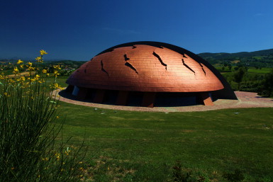
The Carapace at Castelbuono Estate Winery is perfectly representative of biomorphic and zoomorphic architecture. The winery is located in the municipality of Bevagna in Perugia, Italy. The Carapace (Figure 1 ), which was inaugurated in June 2012, was designed by world-famous sculptor Arnaldo Pomodoro (Hunter, 1995 ; Hunter, 1997 ; Studio Arnaldo Pomodoro, 2013). ).
|
|
|
Figure 1. The Carapace at Castelbuono Estate Winery upon complete construction. |
The shape of the structure follows the principles of bio-inspiration and biomorphism. The coverage represents the carapace of a tortoise, and the overall structure exhibits a conjugation of zoomorphism with symbolic aspects.
This study presents the first architectural case in which electroforming process has been applied to a project of considerable dimensions, specifically the scales on the roof of the Carapace.
2. The mind of the artist (based on an interview with Arnaldo Pomodoro)
The tortoise concept emerged from an observation of the undulating hills surrounding the site. A single structure was embedded in such an environment to form only one subject.
The shape of the entire structure creates an organic sense and an evocative power in the minds of observers. A significant aspect of the work is the roof, the surface of the Carapace, which is made of rough copper scales that do not reflect sunlight. The organic characteristic is also present inside the Carapace, where ribs enable observers to link the interior to the exterior, similar to a nut between the shell and the kernel. A central ridge appears to support the entire structure.
In addition to the shape of the tortoise carapace, another trace of bio-inspiration is the resemblance of the top of the carapace to a cuttlefish bone, a recurring symbol in the artistic production of Maestro Pomodoro. The shape of the roof emphasizes this feature, which highlights the back of a prehistoric animal that seems to be slowly approaching the winery.
Similar to Maestro Pomodoros entire body of work, the Carapace model arises from the cutting process of rough material. The carapace structure symbolizes protection. As the tortoise carapace protects the animal (Rhee et al., 2009 ), so does the structure guard wine barriques while conveying a sense of calm reassurance. The tortoise, with its slow gait, is not an aggressive and dangerous animal. Similarly, the winery architecture is amiable and comforting.
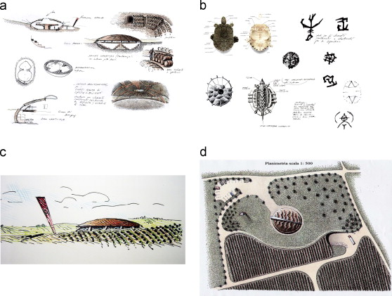
Figure 2 shows the drawings and sketches rendered by Maestro Pomodoro during the design process.
|
|
|
Figure 2. Drawings and sketches rendered by Maestro Pomodoro during the design process (Courtesy Archivio Arnaldo Pomodoro). |
3. Material selection
The choice of the material for the structure was not immediate. Several options were considered (Karana et al ., 2008 ; Wastiels and Wouters, 2012 ), including wood and stone, which were traditionally associated with wine, as well as polymer and composite materials. The final decision favored the construction of a wooden structure and a copper roof.
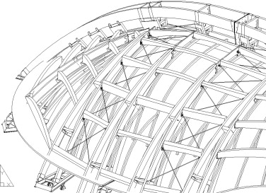
Figure 3 presents an axonometric drawing of the load-bearing roof structure. Fir-wood glued laminated beams were used. A first layer of boards, which generated an ellipsoidal surface, covered the main structure. A first layer made of a waterproof membrane sealed the construction.
|
|
|
Figure 3. Axonometric drawing of the load-bearing roof structure (Courtesy Holz Albertani). |
Production of the designed cuts involved using a second layer made of fir-wood glued laminated beams. Then, the superstructure that defined surface “fractures,” which were formed by laminated beams, was shaped on the basis of the laser scanning of the model in scale. A second layer of waterproof material was deposited on these structures. The surface between the various fractures was made with another layer of fir-wood boards. Then, a final waterproof layer was deposited. Copper plates were further deposited on this surface.
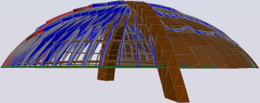
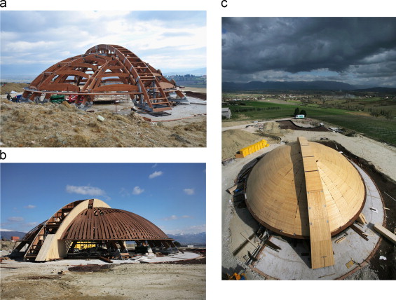
Figure 4 presents the rendering of the structure, whereas Figure 5 describes the steps in structural construction.
|
|
|
Figure 4. Rendering of the roof structure (Courtesy Holz Albertani). |
|
|
|
Figure 5. Steps in constructing the Carapace structure on which the wood ribs are visible. |
Copper was chosen for the roof for several reasons. First, copper and its alloys, such as bronze, found maximum expressiveness in the works of Maestro Pomodoro. Second, copper exhibits excellent resistance to atmospheric corrosion and takes on a protective patina (de la Fuente et al ., 2008 ; Kraetschmer et al ., 2002 ; Mendoza and Corvo, 2000 ; Tuck et al ., 2010 ; Wallinder and Leygraf, 2001 ).
Perception of materials is a fundamental aspect of architecture and design. The chosen material elicits a response from observers who perceive whether the material is hot or cold, colored or not colored, mobile or immobile (Anderson, 2011 ; Bergmann Tiest, 2010 ; Doerschner et al ., 2011 ; Wastiels et al ., 2012 ; Wongsriruksa et al ., 2012 ). Identifying the suitable material is essential to give meaning to the architectural work.
The choice of copper can be associated with a sense of time and life. The tortoise representation indicates an object that wears well and ages wisely. This concept is realized with the use of copper, which oxidizes and covers itself with a patina. This material is perceived as nondegradable and rust resistant, as well as acquires value and meaning over time (Karana et al., 2008 ). The same meaning can be translated to the wine contained in barrels beneath the barriques (Figure 6 ). Over time, the wine acquires a distinct taste and personality.
|
|
|
Figure 6. Section drawing of the project. |
Copper is chosen also because of its positively perceived aging, which brings to mind the dawn of human life. Copper was the first metal used by prehistoric people to produce their tools. Copper is an ancient metal that has survived in the same manner that the tortoise has survived the extinction of many animal species. The perception of copper, similar to that of the tortoise, implies tradition and wisdom, concepts that are applicable to the perception of wine.
4. Production process selection
A number of critical issues needed to be addressed during the project construction. The first issue was transferring the project design and the idea of the artist to the actual structure. Transferring the design to every single part of the coverage was certainly difficult. Nevertheless, the artistic concept needed to be followed to express an organic vision. Reproducing the texture of the actual structure on the basis of the scale model was necessary. According to Maestro Pomodoro, copper sheets cannot be used because they cannot be molded and therefore will not produce the desired effect.
A process that allowed reproducing the design of the artist on copper was considered. One possibility was plastic deformation of the copper plates. Another was covering the panels made by the artist with copper coating or a copper-effect layer. Both suggestions were rejected. With regard to the first suggestion, deforming the plate deep enough to create sharp geometries was infeasible. The second suggestion did not guarantee weathering resistance over time. Therefore, electroforming was proposed and selected as an alternative solution.
The electroforming technique (Rodia, 1995 ) is widely used in the high-precision production of small components, such as microwave devices, EDM electrodes, and MEMS, or of molds for plastics (Hou et al ., 2007 ; Hsieh et al ., 2008 ; Johansen et al ., 2000 ; McGeough et al ., 2001 ; Yarlagadda et al ., 2001 ; Zhu et al ., 2008 ). The metal typically used in the electroforming process is nickel (Grigore, 2000 ; Yarlagadda et al ., 2001 ) because it simplifies work and enables the creation of mechanically resistant thick layers. Nickel also follows the morphology of the substrate. Other metals used in electroforming are copper, silver, and iron (Gillot et al ., 2005 ; Hsu et al ., 2008 ; Rodia, 1995 ; Yarlagadda et al ., 1999 ; Zhu et al ., 2008 ). Through electroforming, metal layers that are hundreds of micrometers up to several millimeters thick can be generated (Rennie et al., 2002; Rodia, 1995 ).
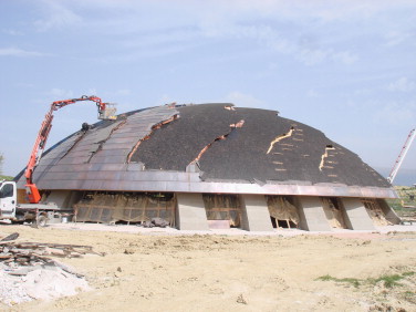
In various cases, the electroforming technique is used in conjunction with rapid prototyping methods to produce both parts and molds in creating polymer injection (Chan et al ., 2003 ; Hsu et al ., 2008 ; Monzon et al ., 2006 , Rennieet al., 2001, Yang and Le, 1999). Applying electroforming to architectural work is considered highly innovative because this technique is frequently used to create objects with limited dimensions. The Carapace project represents the first case in which electroforming is used in a large-scale architectural undertaking. The transfer action is not immediate because the material needs to be deposited and thus pass from a few grams to several hundreds of grams. Creating the entire roof as a single piece was impossible. Therefore, the entire surface was divided into 1,500 pieces (Figure 7 ). After production of the components, they were mounted on the basis of a precise layout, as shown in the figure.
|
|
|
Figure 7. Placement of numerous copper plates on the roof. |
Copper was selected as the material because it met the requirements set by the artist. Furthermore, electroforming of copper involves lower environmental impact than that of nickel. Chemical deposition baths with the least environmental impact were selected.
5. Production procedure
5.1. Production of the copper foils
Production of the copper plates was based on three aluminum matrices created by Maestro Pomodoro. These matrices guided the production of all models, as well as the use of chemical deposition baths to generate the copper scales.
To create the models, a 75 cm×140 cm aluminum plate was deposited on a layer of a two-component polyester resin that contained mineral fillers (called “metallic stucco”). Approximately 30 minutes after crosslinker addition, the materials were ready for use. At this point, the Maestro had given shape to the surface, which was the work to be reproduced.
The large size of the sheet hindered molding by silicone resins because sufficient rigidity during the deposition of copper cannot be guaranteed. Therefore, a composite material mold was produced. Then, a release agent layer was applied to the composite surface. Thereafter, three glass fiber layers were deposited sequentially. The first and third layers functioned as a felt-like material with the randomly arranged fibers. For the intermediate layer, textile was used with the fibers arranged in 0–90-0 order. Impregnation with polyester resin was conducted, followed by curing for 12 hours. Then, the composite matrix was detached; it formed the substrate for manufacturing the copper plate.
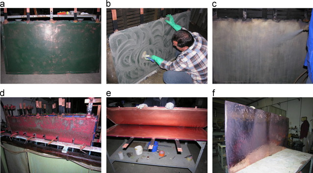
The process of copper layer production via electroforming then started. Figure 8 shows the steps in making the copper plates. Each composite sheet has five current contact tips. All edges are shielded with nonconductive tape. The composite surface is not conductive, which is a necessary condition for electrodeposition. Pretreatment is essential to produce a conductive surface.
|
|
|
Figure 8. Steps in the copper plate production process: a) composite starting surface, b) deposition of the tin ion layer, c) deposition of the silver layer, d) plate after the deposition process, e) detachment of the copper plate, and f) final aspect of the copper plate. |
In the literature, several methods are proposed to create a conductive polymer surface (Yang and Leu, 1999 ). In this production process, creating a surface that was as conductive as possible for the deposition of the copper layer, which will follow the exact shape of the composite, was necessary. Furthermore, the plate should be removed easily from the composite surface after deposition. Other production aspects were also significant. Unlike the other materials used in this project, the interface surface became the external surface. Therefore, eliminating the metallization layer without damaging or modifying the appearance of the copper surface was important.
Metallizing a nonconductive surface involves depositing a metallic flash through evaporation techniques (Kim et al ., 2006 ; Rodia, 1995 ). However, this technique was disregarded because of the large size of the composite sheets. A graphite deposit was attempted (Rennie et al., 2001 ), but this method was not optimal because it did not allow a uniform deposit to be formed. Another alternative was to use a paint loaded with particles of copper or other metals to ensure conductivity (Chan et al ., 2003 ; Monzon et al ., 2006 ). However, this solution was infeasible because obtaining a perfectly conductive surface was difficult to create a perfect replica of the composite surface.
Another possibility was applying the surface activation process with the use of an acidic solution with SnCl2 , followed by a sensitization step in an acidic solution with PdCl2 , as well as surface deposition of metallic palladium nuclei (Grigore, 2000 ; Hsu, 2008). This suggestion was also rejected because detaching the plate with good adhesion properties guaranteed by palladium was difficult. In consideration of high costs, the produced thin palladium flash can also be covered through electroless deposition and not directly through galvanic deposition (Grigore, 2000 ). After detaching the copper plate, the palladium flash cannot be easily removed from the copper surface because of the high electrochemical nobility of palladium.
Finally, the selected process was the use of a sensitization step by immersion in an acidic solution with tin ions (SnCl2 3 g/L30%vol HCl). In this method, a deposit of Sn2+ ions was obtained. Rinsing with demineralized water was conducted to remove the excess acidic solution. Instead of using palladium chloride in the activation process, a solution that contains silver nitrate, ammonia, and formaldehyde in a sugar solution was sprayed on the composite surface (Bertorelle, 1977 ). The exact composition of the solution is confidential. In this process, the composite surface of a thin silver layer was produced from the oxidation product of the ions Sn2+ to Sn4+ and the reduction of the ions Ag2+ to metallic silver (Bertorelle, 1977 ).
After the conductive silver flash was obtained, the electrical connection was created with the current contact tips with the use of conductive paint. Then, the surface was ready for copper galvanic deposition. A classic acidic copper sulfate deposition bath (CuSO4 75 g/L, H2 SO4 100 ml/L) was selected (Bertorelle, 1977 ). This deposition bath has minimal environmental effects and allows the generation of a deposit that follows the matrix geometry with a high deposition rate. Additives, such as brightening, wetting, and burnproofing agents, were used to minimize stress, prevent corrosion, and improve wetness (Ming, 2010 ; Rennie, 2001; Zhu et al. 2008 ). The exact composition of the deposition bath is confidential.
With the large quantity of copper to be deposited, several anodes in the form of Cu-P blocks were located in baskets of titanium on all walls of the bath tank. These copper alloy components were obtained from wire rods. To confine the high quantity of mud, the copper blocks were inserted into filter bags, which allowed the passage of copper ions while holding back the sludge. The deposition temperature was 20 °C and was controlled by a water cooling system. A current density of 3 A/dm2 was applied for 18 hours to obtain an average thickness of 0.8 mm. In each tank, four plates were produced simultaneously.
The contact points between the current contact tips were cut, and the plate was detached after rinsing with demineralized water. The project dimensions of the plate were determined through mechanical processing. The surface in contact with the composite reproduced the design features created by the artist. A 30 wt% solution of HNO3 was used to remove the residual silver on the surface, and this process was followed by rinsing with water jet.
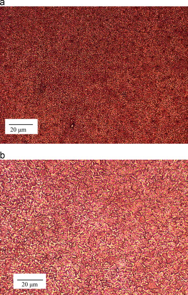
The significant thickness and high formation rate of deposits on the plate resulted in tension characterized by a high hardness value (141±2 HV). The presence of residual stress prevented bending operations that were required to assemble the plates on the roof. Thermal treatment was necessary to reduce the residual stress. This treatment lasted 4 hours to reach 650 °C, 5 hours to ensure permanence at 650 °C, and another 4 hours to return to room temperature. Figure 9 presents the micrographs of the plate before and after heat treatment. After production, the plate exhibited an extremely fine structure because of the high current density used during production, in which the nucleation of new grains was favored respect the growing action. After thermal annealing, the dimension of the grains increased significantly (Figure 9 b), and the hardness was reduced to 86±6 HV. This condition enabled cold metal deformation, which was necessary to install the copper foils. The thermal treatment was not easy to perform because it posed the risk of modifying the design created by the artist.
|
|
|
Figure 9. Metallographic optical pictures of the (a) as-deposited plate and the (b) plate after thermal treatment. |
5.2. Creation of rib cuts on the roof structure
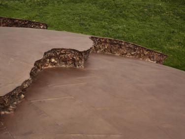
The handworks of Maestro Pomodoro are characterized by moving surfaces of sharp edges and undercuts. The presence of cuts moves the sculpture lines (Corà, 2008 ; Gualdoni, 2007 ; Hunter, 1995 ; Hunter, 1997 ; Studio Arnaldo Pomodoro, 2013). ), as shown in Figure 10 . (The overall view has been presented in Figure 1 ).
|
|
|
Figure 10. Detail of a cut on the roof. |
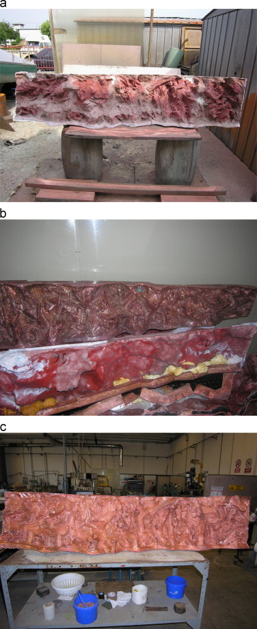
To make these characteristic cuts, a process similar to the plate production was used. A plaster band 20 m wide and 0.4 m high was processed by the Maestro. When the materials were dry, one-meter-long silicone mounds were obtained. They were the matrices used in the subsequent production of fiber glass with polyester resin matrix substrates. These composite structures were placed in an aluminum template for assembly. All of the different pieces were numbered to enable the reconstruction of the starting rib cuts. However, in this case, the electroformed deposit was not detached from the substrate. Finally, the copper surface was polished mechanically to produce a glossy effect. Figure 11 shows the metallization steps for the cuts.
|
|
|
Figure 11. Steps in metallizing the rib cuts: a) fiber glass composite substrate obtained from the artistic design before metallization, b) part after extraction from the deposition bath, and c) polished cut. |
6. Structural assembly
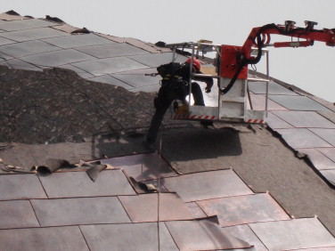
After the thermal treatment, the copper plates were modeled by cuts at the assembly site, as illustrated in Figure 12 . Then, the copper plates were placed on a waterproofing sheath (Chapter 3). Each plate was fixed on the upper border with the use of copper belt fasteners covering 3 cm. These belt fasteners were connected to the copper plate by rivets and to the wainscot by nails. The upper border of the lower plate was seamed mechanically with the lower border of the upper plate. The junction was locked by hammering. Simple seaming was also performed between the side borders of adjacent plates.
|
|
|
Figure 12. Assembly of the copper foils. |
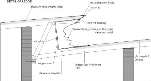
Once all of the copper foils and rib cuts were assembled (Figure 13 ), the surface was polished mechanically. Then, chemical treatment was conducted in accordance with the concept of the artist to produce a uniform surface and highlight the original design.
|
|
|
Figure 13. Schema of the cut structure assembly. |
Several methods to treat copper surface were considered. The chosen process was surface treatment using a solution of potassium sulfide. Subsequently, wax was deposited to produce a browned and weathered effect.
7. Weathering of the copper roof
The issues encountered during the material selection for the roof were natural weathering and corrosion resistance. The significance of the building necessitated materials that can guarantee good corrosion behavior for a long service life. Under natural weathering, copper presents good behavior because of the formation of a patina made of corrosive products (de la Fuente at al., 2008; FitzGerald et al ., 2006 ; Kraetschmer et al ., 2002 ; Marušić et al ., 2009 ; Mendoza and Corvo, 2000 ; Wallinder and Leygraf, 2001 ). However, in the Carapace project, not only technical characteristics, such as corrosion behavior, were important. Aesthetic and perceptive factors had to be considered also.
Natural weathering results in oxidation of the copper surface, which is evident in color and gloss changes. During structural design and construction, one issue encountered was whether maintaining the original aspect of the copper plates or allowing natural change to occur was preferable. Under natural exposure, the corrosion rate and chemical composition of the corrosive product are functions of the type and quantity of pollutants in the location (Kraetschmer et al ., 2002 ; Wallinder and Leygraf, 2001 ). The color can also be changed by environmental factors. A copper patina can form gradually over the years (Kraetschmer et al., 2002 ). As previously stated, a brownish and weathered effect of copper was obtained after final surface treatment. During the life of a tortoise, the age of the animal is reflected by changes in its appearance. If this animal is considered as a symbol of longevity, then the modifications in its appearance can be regarded as positive. Similarly, the color and overall appearance of the copper carapace roof is expected to change over time, a characteristic that can be considered as positive evolution. After approximately 10 months, the copper surface presented a brownish corrosive product layer, which is typical for a structure located in a rural environment (FitzGerald et al ., 2006 ; Kraetschmer et al ., 2002 ; Mendoza and Corvo, 2000 ; Wallinder and Leygraf, 2001 ).
8. Conclusion
The Carapace at Castelbuono Estate Winery is a highly interesting example of biomorphic architecture. The use of copper as roof material allows the structure to develop a good perception effect based on the concept of the tortoise carapace. The copper roof exhibits good natural weathering behavior because of the formation of a patina on its surface, which guarantees a low corrosion rate. Once the oxidation process starts during the natural exposure time of the structure, the color of the copper roof begins to change, as reported in the literature and described in this paper.
Applying the electroforming process to copper plate production demonstrates the possibility of reproducing an artistic design from atelier scale to architectural scale and obtaining an extremely well-defined surface. This case study has presented the first example of the application of electrochemical production to a large-scale architectural project.
Acknowledgement
The authors are grateful to the artist Arnaldo Pomodoro for his insightful discussion of the Carapace design and material selection process, to Giorgio Di Frau and Michele Meneguzzo of Elettroformatura Veneta (Caldogno, Vicenza, Italy) for the information on the copper plate production process, and to Mauro Ognibeni of Eurocoperture (Pergine, Trentino, Italy) for his insights into copper plate assembly.
References
- Anderson, 2011 B.L. Anderson; Visual perception of materials and surfaces; Curr. Biol., 21 (2011), pp. R978–R983
- Bergmann Tiest, 2010 W.M. Bergmann Tiest; Tactual perception of material properties; Vision Res., 50 (2010), pp. 2775–2782
- Bertorelle, 1977 Bertorelle, E., 1977. Trattato di galvanotecnica. U. Hoepli, Milano.
- Biomimetic Patterns in Architectural Design, 2009 Biomimetic Patterns in Architectural Design; Archit, Design, 79 (6) (2009), pp. 74–81
- Cannavale et al., 2010 A. Cannavale, F. Fiorito, M. Manca, G. Tortorici, R. Cingolani, G. Gigli; Multifunctional bioinspired sol-gel coatings for architectural glasses; Build. Environ, 45 (2010), pp. 1233–1243
- Chan et al., 2003 S.F. Chan, C.K. Law, T.T. Wong; Re-engineering the roto-casting mould making process; J. Mater. Process. Tech, 139 (2003), pp. 527–534
- Corà, 2008 B. Corà (Ed.), Arnaldo Pomodoro. Grandi opere (1972-2008). Catalogo della mostra, Fondazione Arnaldo Pomodoro, Milano (2008)
- de la Fuente et al., 2008 D. de la Fuente, J. Simancas, M. Morcillo; Morphological study of 16-year patinas formed on copper in a wide range of atmospheric exposures; Corros. Sci, 50 (2008), pp. 268–285
- Doerschner et al., 2011 K. Doerschner, R.W. Fleming, O. Yilmaz, P.R. Schrater, B. Hartung, D. Kersten; Visual motion and the perception of surface material; Curr. Biol., 21 (2011), pp. 2010–2016
- Engineering Ecologies, 2008 Engineering Ecologies; Archit. Design, 78 (2) (2008), pp. 96–101
- Feuerstein, 2002 G. Feuerstein; Biomorphic architecture, Human and animal form in architecture; Edition Axel Menges, Stuttgart (2002)
- FitzGerald et al., 2006 K.P. FitzGerald, J. Nairn, G. Skennerton, A. Atrens; Atmospheric corrosion of copper and the colour, structure and composition of natural patinas on copper; Corros. Sci., 48 (2006), pp. 2480–2509
- Gillot et al., 2005 F. Gillot, P. Mognol, B. Furet; Dimensional accuracy studies of copper shells used for electro-discharge machining electrodes made with rapid prototyping and the electroforming process; J. Mater. Process. Tech, 159 (2005), pp. 33–39
- Grigore, 2000 L. Grigore; Metallic microstructures by electroplating on polymers: an alternative to LIGA technique; Mat. Sci. Eng. B-Solid, 74 (2000), pp. 299–303
- Gualdoni, 2007 F. Gualdoni (Ed.), Catalogo ragionato della scultura, Arnaldo Pomodoro, Skira, Milano (2007)
- Hou et al., 2007 K.H. Hou, M.C. Jeng, M.D. Ger; A study on the wear resistance characteristics of pulse electroforming Ni–P alloy coatings as plated; Wear, 262 (2007), pp. 833–844
- Hsieh et al., 2008 S.S. Hsieh, C.F. Huang, C.L. Feng; A novel design and micro-fabrication for copper (Cu) electroforming bipolar plates; Micron, 39 (2008), pp. 263–268
- Hsu et al., 2008 C.Y. Hsu, D.Y. Chen, M.Y. Lai, G.J. Tzou; EDM electrode manufacturing using RP combining electroless plating with electroforming; Int. J. Adv. Manuf. Technol., 38 (2008), pp. 915–924
- Hunter, 1995 S. Hunter; Monography of Arnaldo Pomodoro; Fabbri Editori, Milano (1995)
- Hunter, 1997 S. Hunter; Sphere within a Sphere for the UN Headquarters; Roma, Il Cigno Galileo Galilei (1997)
- John et al., 2005 G. John, D. Clements-Croome, G. Jeronimidis; Sustainable building solutions: a review of lessons from the natural world; Build. Environ, 40 (2005), pp. 319–328
- Johansen et al., 2000 L.S. Johansen, M. Ginnerup, J.T. Ravnkilde, P.T. Tang, B. Loechel; Electroforming of 3D microstructures on highly structured surfaces. Sensor; Actuator, 83 (2000), pp. 156–160
- Karana et al., 2008 E. Karana, P. Hekkert, P. Kandachar; Material considerations in product design: A survey on crucial material aspects used by product designers; Mater. Design., 29 (2008), pp. 1081–1089
- Kim et al., 2006 D.S. Kim, H.S. Lee, B.K. Lee, S.S. Yang, T.H. Kwon; Replications and analysis of microlens array fabricated by a modified LIGA process; Polym. Eng. Sci., 46 (2006), pp. 416–425
- Kraetschmer et al., 2002 A. Kraetschmer, I. Odnevall Wallinder, C. Leygraf; The evolution of outdoor copper patina; Corros. Sci., 44 (2002), pp. 425–450
- Li et al., 2012 F. Li, W. Liu, X. Fu, G. Bonsignori, U. Scarfogliero, C. Stefanini, P. Dario; Jumping like an insect: Design and dynamic optimization of a jumping mini robot based on bio-mimetic inspiration; Mechatronics, 22 (2012), pp. 167–176
- Marušić et al., 2009 K. Marušić, H. Otmačić-Ćurković, S. Horvat-Kurbegović, H. Takenouti, E. Stupnišek-Lisac; Comparative studies of chemical and electrochemical preparation of artificial bronze patinas on their protection by corrosion inhibitor; Electrochim. Acta, 54 (2009), pp. 7106–7113
- McGeough et al., 2001 J.A. McGeough, M.C. Leu, K.P. Rajukar, A.K.M. De Silva, Q. Liu; Electroforming process and application to micro/macro manufacturing; CIRP Ann. Manuf. Technol, 50 (2001), pp. 499–514
- Mendoza and Corvo, 2000 A.R. Mendoza, F. Corvo; Outdoor and indoor atmospheric corrosion of non-ferrous metals; Corros. Sci., 42 (2000), pp. 1123–1147
- Menon et al., 2009 C. Menon, R. Brodie, S. Clift, J.F.V. Vincent; Concept design of strain sensors inspired by campaniform sensilla; Acta. Astronaut., 64 (2009), pp. 176–182
- Ming et al., 2010 P.M. Ming, D. Zhu, Y.B. Zeng, Y.Y. Hu; Wear resistance of copper EDM tool electrode electroformed from copper sulfate baths and pyrophosphate baths; Int. J. Adv. Manuf. Technol., 50 (2010), pp. 635–641
- Monzon et al., 2006 M.D. Monzon, M.D. Marrero, A.N. Benitez, P.M. Hernandez, J.F. Cardenes; A technical note on the characterization of electroformed nickel shells for their application to injection molds; J. Mater. Process. Tech, 176 (2006), pp. 273–277
- Nagaraja and Yao, 2007 P. Nagaraja, D. Yao; Rapid pattern transfer of biomimetic surface structures onto thermoplastic polymers; Mat. Sci. Eng. C-Biomim, 27 (2007), pp. 794–797
- Rennie et al., 2001 A.E.W. Rennie, C.E. Bocking, G.R. Bennett; Electroforming of rapid prototyping mandrels for electro-discharge machining electrodes. J. Mater. Process; Tech, 110 (2001), pp. 186–196
- Rhee et al., 2009 H. Rhee, M.F. Horstemeyer, Y. Hwang, H. Lim, H. El Kadiri, W. Trim; A study on the structure and mechanical behavior of the Terrapene carolina carapace: A pathway to design bio-inspired synthetic composites; Mat. Sci. Eng. C-Biomim, 29 (2009), pp. 2333–2339
- Rodia, 1995 C.M. Rodia; Electroforming. Met. Finish, 93 (1995), pp. 369–378
- Salvia et al., 2009 G. Salvia, V. Romagnoli, M. Levi; Il progetto della natura – gli strumenti della biomimesi per il design; Franco Angeli, Milano (2009)
- Singh et al., 2012 A.V. Singh, A. Rahman, N.V. Sudhir Kumar, A.S. Aditi, M. Galluzzi, S. Bovio, S Barozzi, E. Montani, D. Parazzoli; Bio-inspired approaches to design smart fabrics; Mater. Design., 36 (2012), pp. 829–839
- Studio Arnaldo Pomodoro, 2013). Studio Arnaldo Pomodoro, 〈http://www.arnaldopomodoro.it/en〉 (accessed on March 2013).
- Tuck et al., 2010 C.D.S. Tuck, C.A. Powell, J. Nuttall; Corrosion of copper and its alloys, in Shreirs Corrosion; 1937-1973, Elsevier, Amsterdam (2010), p. 3
- Wallinder and Leygraf, 2001 I.O. Wallinder, C. Leygraf; Seasonal variations in corrosion rate and runoff rate of copper roofs in an urban and a rural atmospheric environment; Corros. Sci, 43 (2001), pp. 2379–2396
- Wastiels et al., 2012 L. Wastiels, H.N.J. Schifferstein, A. Heylighen, I. Wouters; Relating material experience to technical parameters: A case study on visual and tactile warmth perception of indoor wall materials Build; Environ, 49 (2012), pp. 359–367
- Wastiels and Wouters, 2012 L. Wastiels, I. Wouters; Architects' considerations while selecting materials; Mater. Design., 34 (2012), pp. 584–593
- Wongsriruksa et al., 2012 S. Wongsriruksa, P. Howes, M. Conreen, M. Miodownik; The use of physical property data to predict the touch perception of materials; Mater. Design., 42 (2012), pp. 238–244
- Yang and Leu, 1999 B. Yang, M.C. Leu; Integration of rapid prototyping and electroforming for tooling application; CIRP Ann. Manuf. Technol, 48 (1999), pp. 119–122
- Yang et al., 2011 X. Yang, Z. Peng, H. Zuo, T. Shi, G. Liao; Using hierarchy architecture of Morpho butterfly scales for chemical sensing: Experiment and modeling. Sensor; Actuat. A-Phys., 167 (2011), pp. 367–373
- Yarlagadda et al., 1999 P.K.D.V. Yarlagadda, P. Christodoulou, V.S. Subramanian; Feasibility studies on the production of electro-discharge machining electrodes with rapid prototyping and the electroforming process; J. Mater. Process. Tech, 89-90 (1999), pp. 231–237
- Yarlagadda et al., 2001 P.K.D.V. Yarlagadda, IP Ilyas, P. Christodoulou; Development of rapid tooling for sheet metal drawing using nickel electroforming and stereolithography processes; J. Mater. Process. Tech., 111 (2001), pp. 286–294
- Zhou, 2000 B.L. Zhou; Bio-inspired study of structural materials; Mat. Sci. Eng. C- Biomim, 11 (2000), pp. 13–18
- Zhu et al., 2008 Z.W. Zhu, D. Zhu, N.S. Qu; Synthesis of smooth copper deposits by simultaneous electroforming and polishing process; Mater. Lett., 62 (2008), pp. 1283–1286
Document information
Published on 12/05/17
Submitted on 12/05/17
Licence: Other
Share this document
claim authorship
Are you one of the authors of this document?
